Alarm Clock with Voice Recognition
David Lee, djl347
Nicholas Tan, nt325
Tariq Kane, tk375
Introduction
“Tell your clock to shut up”
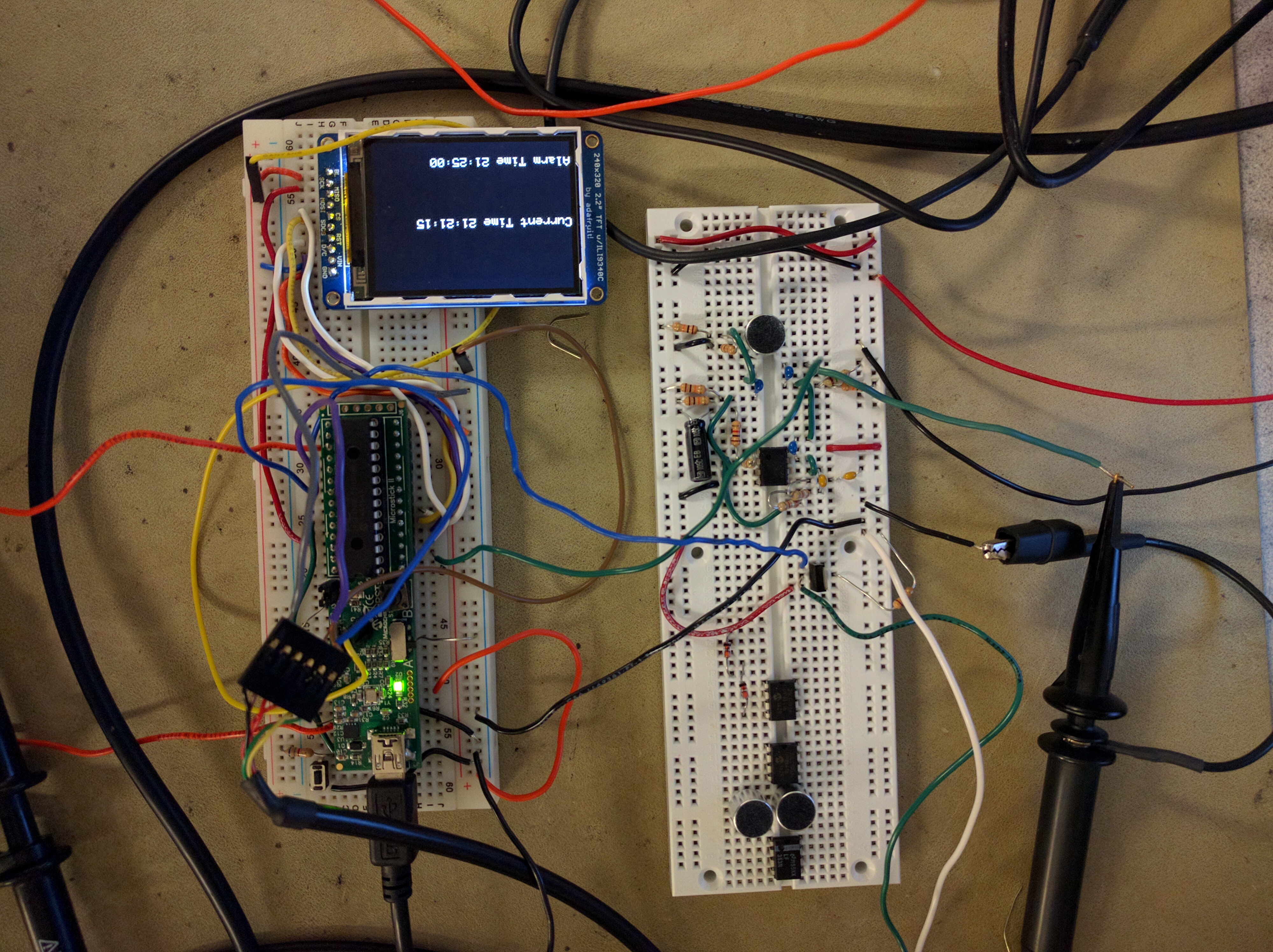
The alarm clock with voice recognition is a project that recognizes simple commands to turn off or snooze the alarm clock. The clock consists of a PIC32 microprocessor, a TFT display, speaker, and microphone. (Picture of system can be placed here.)
As students who constantly lack sleep on a regular basis, we believe that an alarm clock that requires the user to be awake and comprehensible would help students become more alert when they wake up. Thus, by requiring the user to repeat certain phrases to execute specific commands, this would allow the user to be in a more attentive state when he or she wakes up.
High Level Design
Sources
Our sources started with the real-time clock and calendar (RTCC) hardware module embedded in the PIC32 microcontroller, referenced in section 29 of the reference manual. The RTCC module has the capability of setting and keeping track of real time as well as setting and triggering alarms.
We have also extensively researched reading the literature on reading spectrograms. Rob Hagiwara’s short tutorial https://home.cc.umanitoba.ca/~robh/howto.html has been instructive in the practical applications of speech recognition.
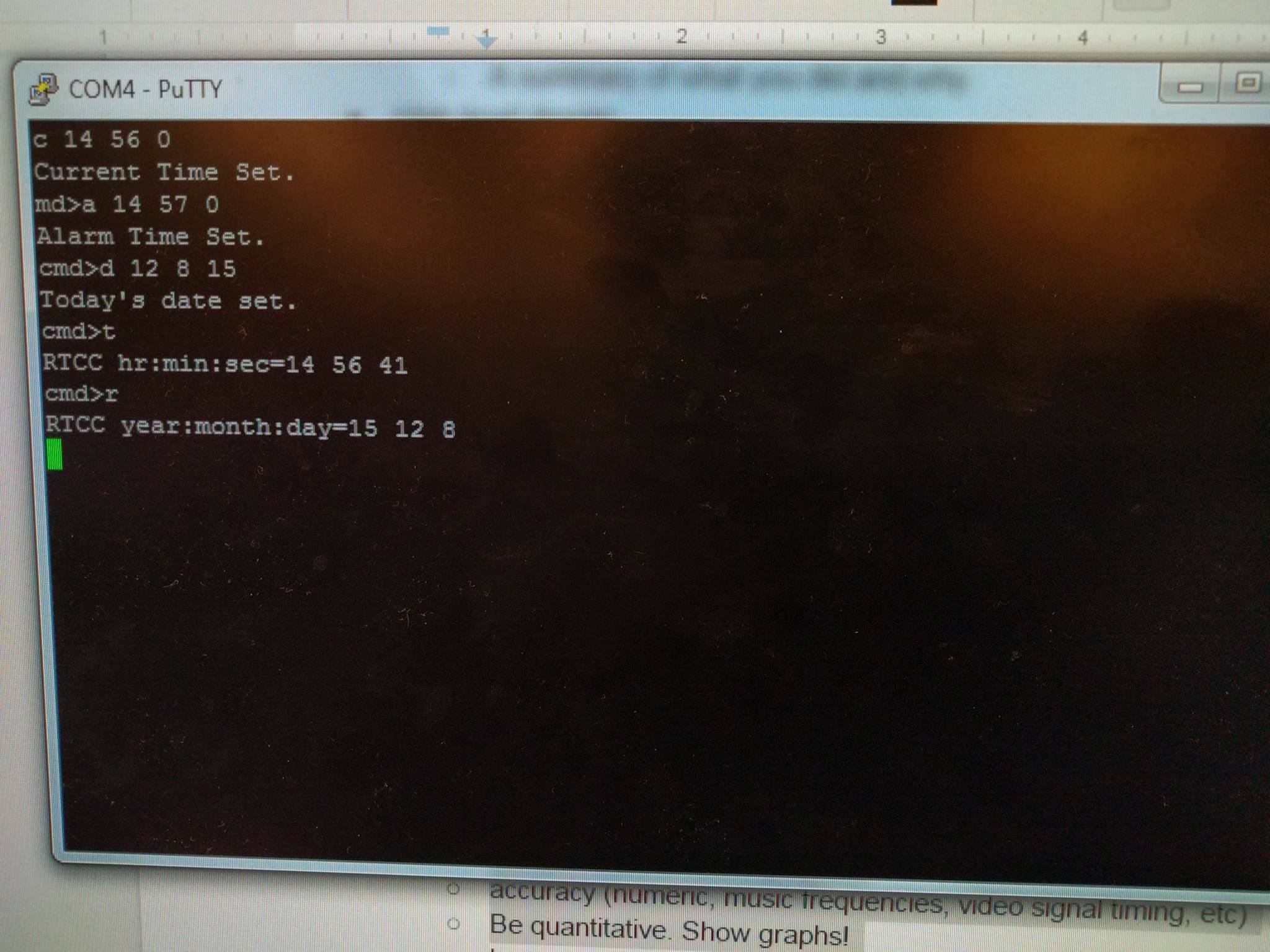
We also referenced lab 4 of the ECE 4760 class during the Fall semester of 2015 for the UART serial interface. This was used to set up the console used to set up the current time, alarm time, and date of our system.
Logical Structure
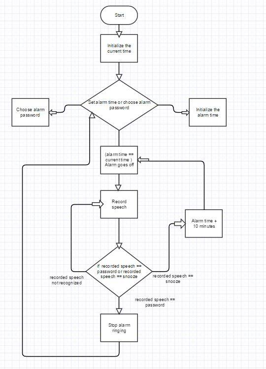
The alarm clock system boots up at 00:00:00 military time with a preset date and alarm time, and is recommended to be set up by the user. The clock will continue to display and keep the current time as a normal clock should, until a defined alarm time is met. At this point, an interrupt flag is triggered within the system and a signal is sent to the buzzer to play the alarm sound indefinitely. In this state, the system waits for the pushbutton to be pressed, which will change the display to a spectrogram and initiate the microphone to start listening for a phrase from the user. The alarm will continue to sound off until the correct phrase is recognized, which at this point will stop the alarm sound. Depending on which phrase is detected, the alarm will be shut off until the following day at the same time, or “snoozed” so that the alarm time is updated by 10 minutes from the initial alarm time. Finally, the system reverts back to the initial state of displaying and keeping time and date.
Hardware/Software Tradeoffs
Hardware is limited in this project due to the allotted spacing on the breadboards used. There is not enough room to build upward, so we had to limit the amount of components we could add without expanding horizontally. Moreover, sampling speech requires memory to store the data, and due to the limitations of the PIC32, hardware was compromised through software by predefining phrases and pre-training the MCU to recognize them. This has allowed us to use the 32kB on chip instead of using any external memory since we do not need to store the entirety of our training waveforms and only the coefficients needed for our learning.
Industry Standards
Our project follows the IEEE Code of Ethics, which outlines the responsibility for safety, avoidance of conflicts of interest, integrity, rejection of bribery, qualification of technological tasks, handling criticism and credit of contribution, fairness and equality, and cooperation and assistance. We adhere to these standards and work to not violate any of these codes in our project. Through creating a fully functional alarm clock without threatening features, such as time ticking sounds or countdown displays, working together and asking for help when needed, avoiding plagiarism and falsification of data, and refusing funds or benefits in return for services, we will comply with the IEEE standards.
Legal Content
There have been patents for alarm clocks and voice recognition systems in past, and recently some systems have built off them. These patents include but are not limited to a voice-controlled timing and calculating device (EP0964331 A1), voice recognition interface with a programmable timekeeping device (WO1997015045 A1), speech recognition in consumer electronic products (US20020091513 A1), and an interactive voice recognition digital clock (US6310833 B1). A recent patent relevant to our project is EP1406133 A2. which is a patent for a voice-commanded alarm clock system with an associated method, filed in October 2003 and published on April 2004. This patent was for an alarm clock system that performed various tasks based on voice commands, such as “turn alarm on”.
Program/Hardware Design
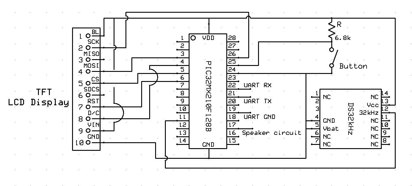
Hardware
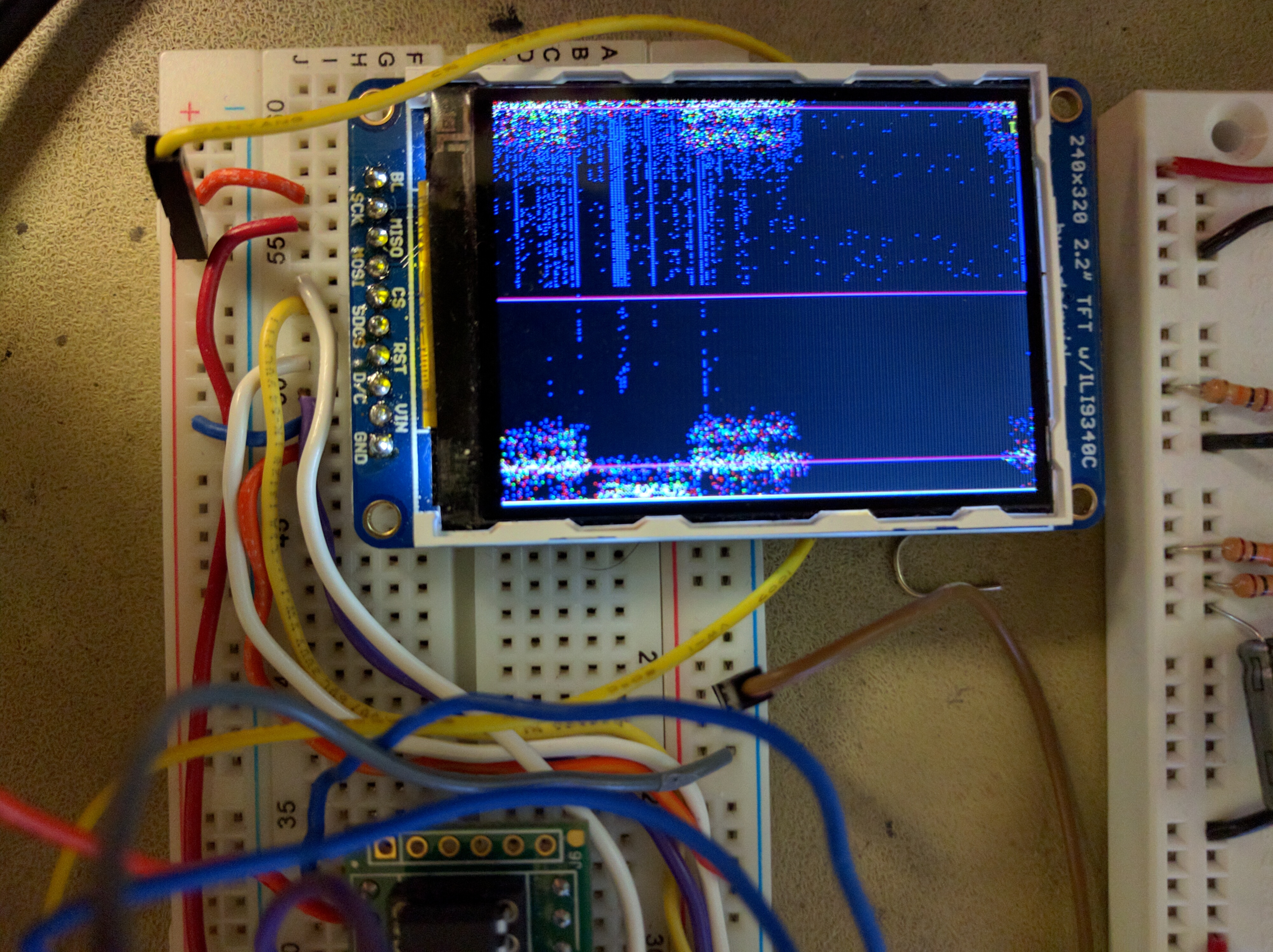
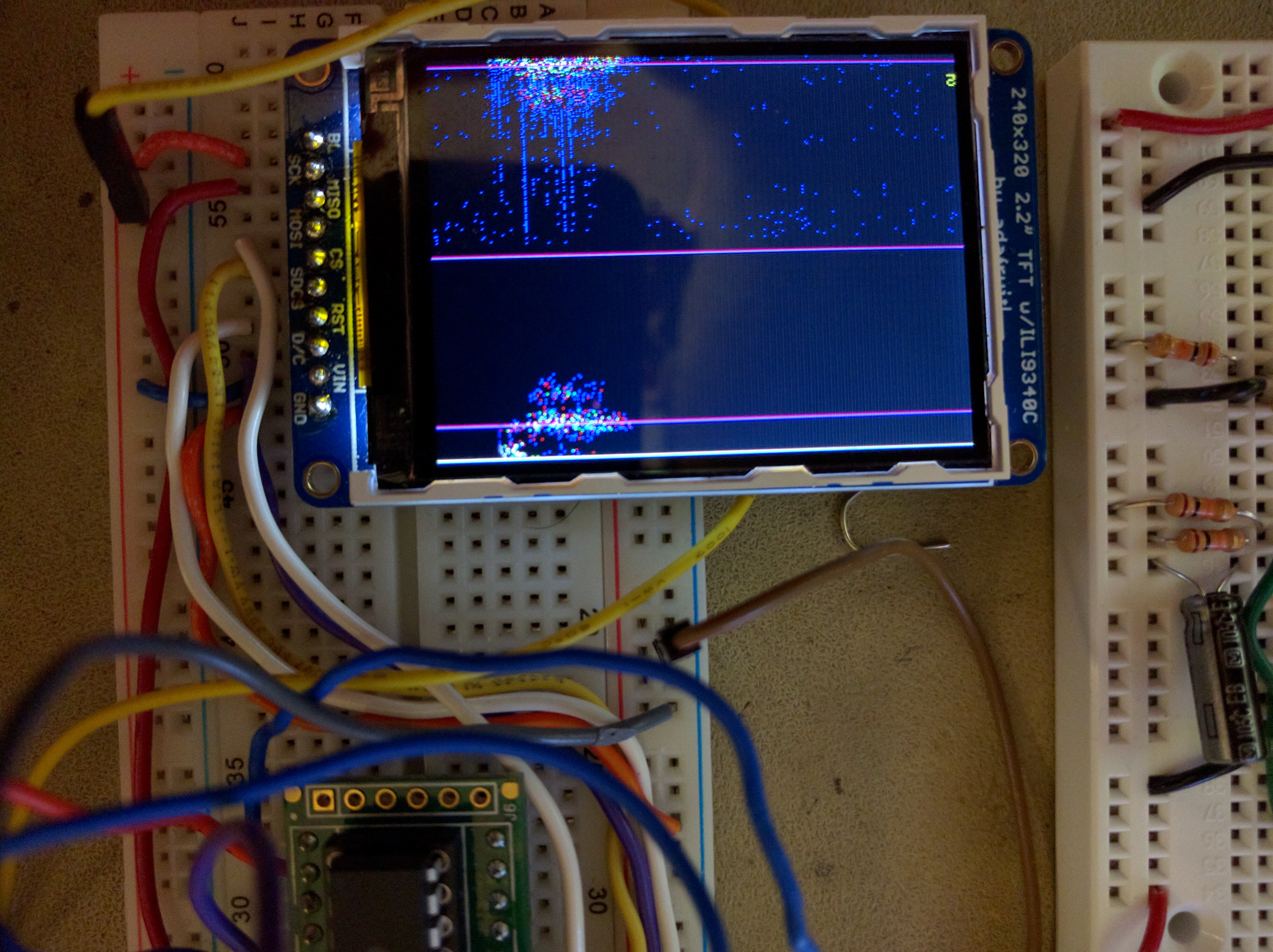
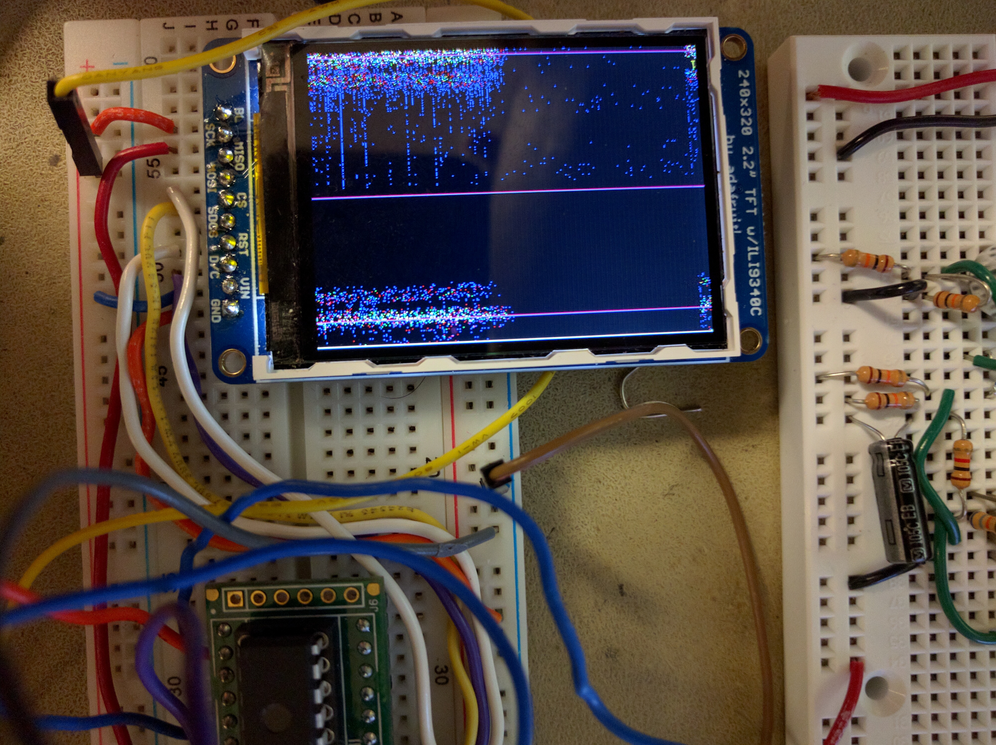
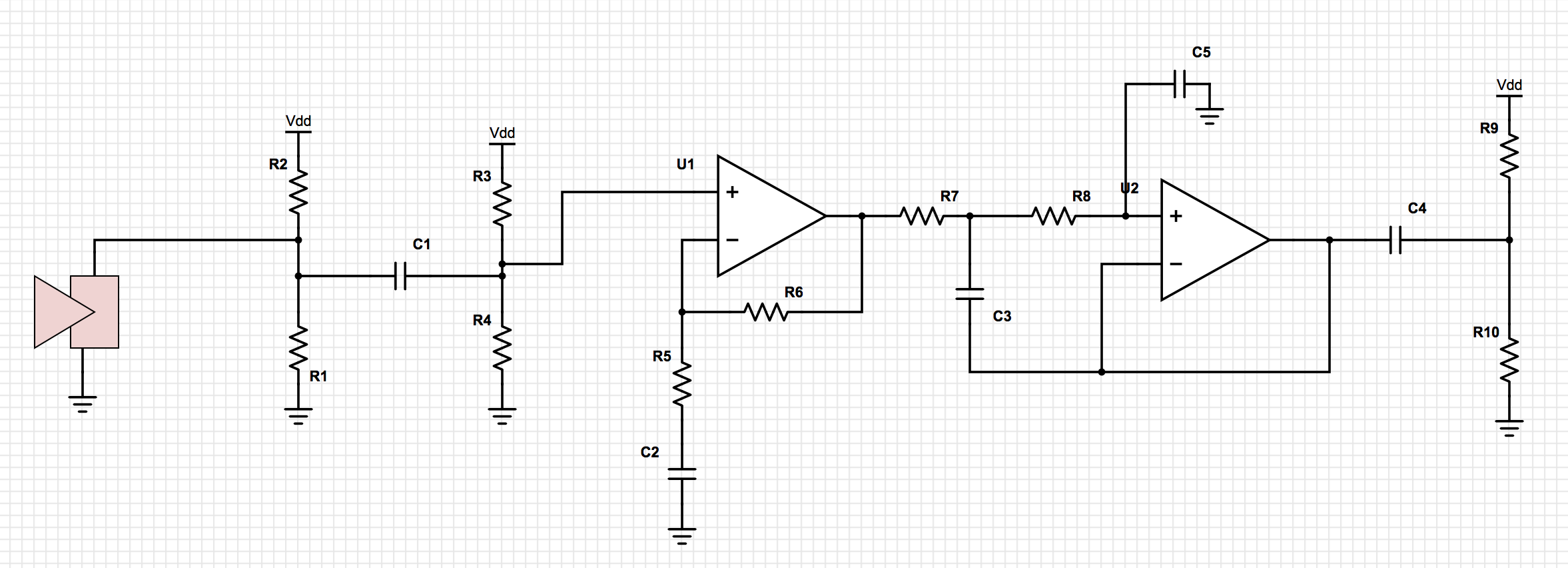
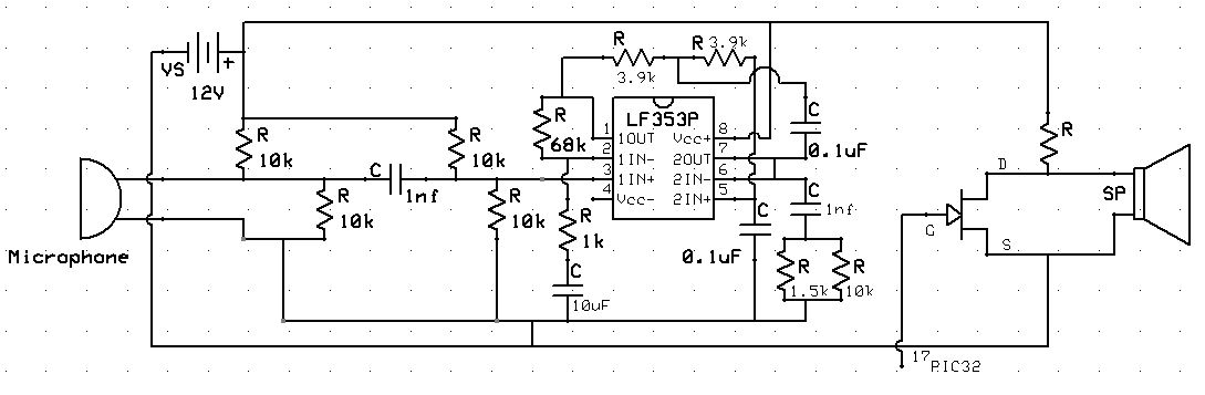
The hardware for the project consisted of the PIC32 microcontroller, microphones, a TFT LCD display, a UART serial cable, a buzzer for the alarm sound, and an external pushbutton. The schematic for the entire system is depicted in the Appendix section. The microphones detects the voice commands from the user which is then amplified and filtered for better sound capture. The TFT display shows the date, current time in military format, and the alarm time in military format. The TFT was also used to show a spectrogram of the voice recognition when the pushbutton is pressed, which determines when to capture speech when the alarm goes off. The UART serial communication allows the user to set the time and date using a UART console and a keyboard on a computer as well as the alarm time.
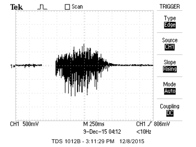
The circuit for the microphone consisted of a gain stage and a filtering stage. For the gain stage, we used an op amp in negative feedback as a non-inverting amplifier. The gain stage had a gain of A_v = 69. This allowed us to have a maximum 2.5 V peak to peak waveform at the output on average when everyday speech was at the input. We designed an extra 0.5 V of headroom for protection for the PIC, since the maximum tolerance of the ADC pin was 3.3 V. Additionally, we included some clamping diodes on the input to the ADC for extra protection. The filtering stage of the microphone circuit was a butterworth filter with a cutoff frequency of 20 kHz. We designed this cutoff because, in general, human hearing finds it hard to pick up sounds above this frequency. This has also influenced our sampling frequency in software - we sample at twice of 20 kHz = 40 kHz to satisfy the Nyquist criterion.
We also had a simple circuit to drive our buzzer. The signal to produce the sound came from the PIC and was thus at 3.3V. However, our buzzer performed at 12 V and thus we used an NFET to amplify our signal and carry the necessary currents for the speaker.
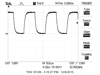
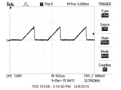
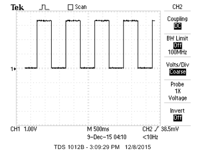
The last piece of hardware relevant to our design was the secondary oscillator. The oscillator was powered by the 3.3 V voltage outputted by the PIC32 so that its output could be connected to PIC32 safely. The 32 kHz output of the secondary oscillator was connected to the SOSCI port, pin 11, on the PIC32. The PIC32 microcontroller contains an internal oscillator which can be used to keep track of time, yet due to the limitations of the internal oscillator, timekeeping could prove to be inaccurate due to limited frequency and changes in temperature. Moreover, the internal oscillator could cause instability of the system, leading to unreliable UART communication. The secondary oscillator is a component with a 32 kHz crystal inside that was added to provide stability and low power operation functionality for keeping track of time accurately.
Below are the waveforms from the oscillator (from the source and on the PIC). Additionally, note that they are at 32 kHz and we are able to produce a square wave at exactly 1 Hz
Software
Our project uses protothreads to run various processes concurrently. These processes consist of displaying the current time and the alarm time on the TFT, recognizing the push button for voice commands, and running the UART for keyboard commands from the user for multiple functions, including setting the alarm and current time, displaying the current time on the UART console, and clearing the current time. Lastly, one protothread is reserved for calculating the FFT.
When the current time is equal to the alarm time, an interrupt is triggered and a boolean variable is set so that our micro controller outputs square waves of chosen frequency to the buzzer. To turn off the sound we press a button to run the fft and record our speech. Our micro controller has to identify the word based on the spectrogram of our recorded word to the words in our database. If the matching is above a certain threshold then the alarm buzzer stops ringing. We trained four words/phrases, “shush”, “stop”, “snooze” (to delay the alarm time), and “shut up”. When the FFT is run the program enters into a state machine. The state machine has a state for each sound of the word for the password in our database that will turn off the alarm. Each sound is compared to that of the spoken word and if the syllable matches we move on to the next state. The final state stops the buzzer.
We will go through “shush” as an example. We assume now that the alarm has been set. We hold a boolean alarm state variable that captures this. Clearing this variable will turn the alarm off. The first state of “shush” is the first sound “sh.” This sound is a fricative, which is characterised by broadband noise with a peak at a certain frequency. Our training has shown that this frequency is at around 2.5kHz for “sh” specifically. We check for these features and move to the next state when we find them to strongly match. The next state is “uh,” which is a vowel. For vowels, we look for the formants, which are the peaks caused by the filtering of the spectrogram by the vocal tract. For "uh" specifically, the formants are at 400Hz and 1100Hz. Our system will check our spectrogram at these frequencies. If we find another match, we move on to “sh” again and check for another match. If a match is found, we will turn off the alarm by clearing the alarm boolean and reset the state machine.
Results
We based the success of our project based on the following criteria:
- Ability to turn off the alarm based on spoken password.
- The strength of our speech recognition against words or phrases that are not our password.
For the first criterion we had 3 built in words/phrases that could turn off our alarm clock. The three words/phrases are “shushh”,” stop”, and “shut up”. We had another word “snooze” to postpone the alarm time. The shushh and shut up options showed 92% accuracy in turning off the alarm while the stop option shut off 83% of the time. This is because the spikes in our spectrogram when pronouncing the “t” and “p” part of “stop” restarted the pic32. The “snooze” keyword postponed the alarm clock 80% of the time. To get better accuracy we have to elongate the “oo” part of “snooze” when speaking into the microphone.
For the second criterion we test the strength of our four keywords/phrases. For the “shushh” option we found that there was 90% accuracy on reasonable words. The “stop” option had the smallest accuracy of 78% against reasonable words. The “shut up” option had 85% accuracy and the “snooze” option did not break under reasonable words.
We are able to increase the strength of our passwords against other words that are not the keyword but we would lose accuracy in the success of the keyword. We believed that these success/failure rate we the most ideal for our alarm clock project.
video link for "snooze,"
video link for "shut up,"
video link for "shush,"
video link for "stop,"
Conclusion
Overall, our project fully functions as an alarm clock with clear displays of the current time and date as well as the configured alarm time. The date and times can also be set by the user with multiple options for phrases for voice recognition.
To improve on the project, we can change the interface from the UART console to the TFT alone using a keypad to set the times of the clock and alarms. This would allow the user to use the clock simply off a power source or battery rather than having to use a computer and keyboard to control the clock. Moreover, if we powered the clock on an external power supply, we could activate sleep mode on the PIC32 to conserve on power since the RTCC module will continue to run and keep track of time in sleep mode. A chassis to contain and cover the clock would also aesthetically improve the project.
Intellectual Property Considerations
A large portion of our code was based off examples written and provided by our professor Bruce Land. Specifically, the setup for the RTCC module and UART serial communication were extracted from sample code linked in the Reference section. The majority of speech recognition code was created from scratch, with some help and code reference from our TA Tahmid Mahboub. However, there are many patents revolving around voice recognition, alarm clocks, and a combination of both of them, and would require us to consider many of them if we were to pursue this project beyond the classroom and laboratory environment.
Ethical Considerations
This project complies with the IEEE Code of Ethics and was considered throughout the development of the system. There was no form of monetary incentive involved in creating this project, nor was there intent in making a profit from it. Moreover, all safety concerns were recognized; no offensive words were used in the voice recognition, no threat to a person’s wellbeing or background was made, and physical harm was avoided in the construction of the system, given the constraints of the project and its features. Help was given and accepted when needed, and constructive criticism was welcomed for improvements to the project. All ideas that were implemented were within the reach of our knowledge, with some areas challenging enough but not impossible for us given the limitations of budget, time, and resources.
The project was created for educational purposes, and we maintain the integrity of the IEEE Code of Ethics. We give credit to all code and ideas referred to in the creation of this project and make all aspects of the project transparent. We give permission to others who would like to use content from our project for the development of their own, and are open to accept feedback from the community regarding our project.
Legal Considerations
Our project does not violate nor present any consequential legal issues. All information is made available to the public, and we do not infringe on any current patents.
Appendix
Code
Main file
Schematics and Hardware
Parts and Costs
|
Part
|
Price
|
Quantity
|
Vendor
|
Cost
|
|
MicroStickII
|
$10
|
1
|
Lab stock
|
$10
|
|
whiteboard
|
$6
|
2
|
Lab stock
|
$12
|
|
PIC32MX250F128B
|
$5
|
1
|
Lab stock
|
$5
|
|
LCD TFT display
|
$5
|
1
|
Lab stock
|
$5
|
|
microphone
|
-
|
1
|
Lab stock
|
-
|
|
pushbutton
|
-
|
1
|
Lab stock
|
-
|
|
DS32kHz DIP oscillator
|
$12.25
|
1
|
Digi-Key
|
$12.25
|
|
LF353 Amplifier
|
-
|
1
|
Lab stock
|
-
|
|
UART serial cable
|
-
|
1
|
Lab stock
|
-
|
|
Resistors
|
-
|
12
|
Lab stock
|
-
|
|
Capacitors
|
-
|
5
|
Lab stock
|
-
|
|
Total Cost
|
$44.25
|
Distribution of Tasks
All tasks were distributed evenly amongst the group members
Reference
PIC32 Reference Manual, Section 29 - RTCC Module
http://ww1.microchip.com/downloads/en/DeviceDoc/61125F.pdf
Rob Hagiwara’s tutorial on spectrograms
https://home.cc.umanitoba.ca/~robh/howto.html
Datasheets
PIC32MX2XX
http://ww1.microchip.com/downloads/en/DeviceDoc/60001168F.pdf
DS32KHz DIP secondary oscillator
http://datasheets.maximintegrated.com/en/ds/DS32kHz.pdf
LF353 Op-Amp
http://www.ti.com/lit/ds/symlink/lf353.pdf
2SK4017 FET
http://alltransistors.com/pdfview.php?doc=2sk4017.pdf&dire=_toshiba
Vendor Sites
Digi-Key
http://www.digikey.com/
Borrowed Code/Designs
Bruce Land’s example codes
http://people.ece.cornell.edu/land/courses/ece4760/PIC32/RTCC/RTCC_test.c
http://people.ece.cornell.edu/land/courses/ece4760/PIC32/PLIB_examples/plib_examples/rtcc/time_date/source/time_date.c
http://people.ece.cornell.edu/land/courses/ece4760/PIC32/PLIB_examples/plib_examples/rtcc/alarm/source/alarm.c