
Introduction:
The goal of this project was to build a field-portable stimulator for amphibians.
Specifications:
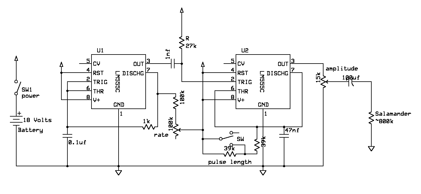
The 555 timers shown below are actually 7555 CMOS variants. This is revision 2 of the circuit. The revision 1 schematic is here.
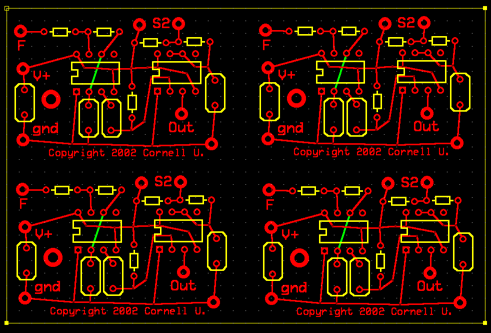
The PC board was layed out in expresspcb.com software. To view the design file, you need to download their software. The board shown below has 4 copies of the circuit.
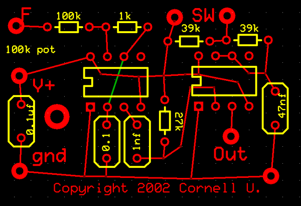
The parts layout is shown below. Note that the 100k potentiometer is actually mounted on the box with two leads going to points F and V+. The two points marked SW are the connections for two terminals of a switch to set pulse length. The 18 volt battery is connected in series with a power switch and then to V+ and gnd. The 15k potentiometer top lead goes the point marked Out, and its bottom lead goes to gnd. The middle lead of the 15k potentiometer goes through the output capacitor to the actual output terminals.