Introduction
We want to use artifical neural systems to teach biological instrumentation methods. The goal is a set of small circuits which behave like neural systems with respect to voltage, timing, and system behavior. This will enable students to exercise their skills in setting up amplifiers and oscilloscopes, getting rid of noise, connecting to a computer and writing software , while concentrating on the electronic technology, rather than the biological technology. We believe that modeling is no substitute for work with real animals, but modeling can help in understanding electronic and logical concepts before the students use real animals.
Model light receptors
Mpegs of the circuit and scope show:
We built a simple model of an array of light sensors with the following properties:
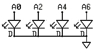
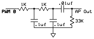
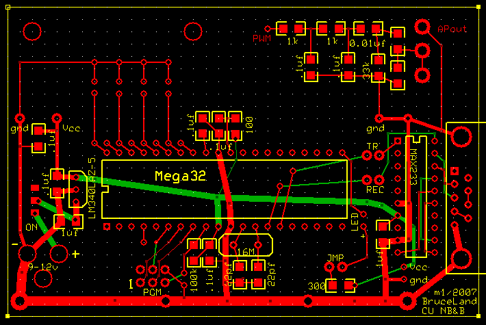
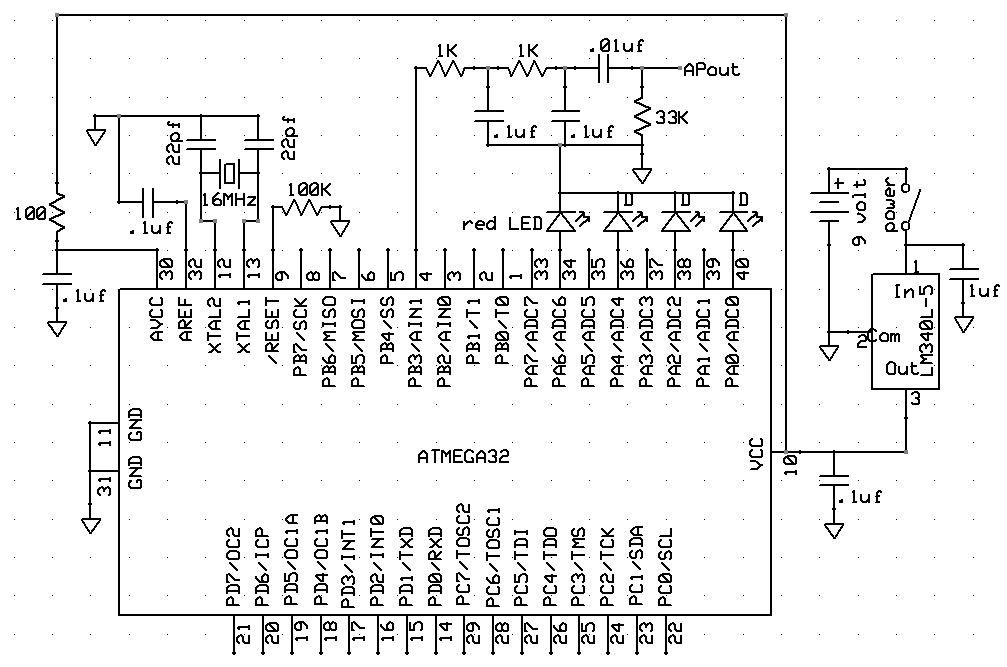
The circuit board (expresspcb.com format file) has mounting holes for 4 LEDs. The output PWM filter is on the upper-right. The two rightmost 1206 pads do not have marked component values. They can be used to build a voltage divider to implement the desired output impedance and voltage level. The board layout is derived from the Mega32 development board built for ECE476. An image of the populated board and the full schematic is below.

The Codevision C program running on the Mega32 microcontroller consists of three parts:
v[0] = v[0] - (v[0]>>6) + (neuronInput[0]<<gain1) - (neuronInput[1]<<gain1) ;

      v[1] = v[1] - (v[1]>>6) + (neuronInput[1]<<gain1) - (neuronInput[0]<<gain2) - (neuronInput[2]<<gain2) ;

      v[2] = v[2] - (v[2]>>6) + (neuronInput[2]<<gain1) - (neuronInput[1]<<gain2) - (neuronInput[3]<<gain2) ;

v[3] = v[3] - (v[3]>>6) + (neuronInput[3]<<gain1) - (neuronInput[2]<<gain1) ; >>6 corresponds to a membrane time constant of a few mSec. The indices refer to cell number.
// detect threshold crossing
if (v[i] > threshold )
begin
    // set the amplitude, duration, refactory period
    ap[i] = 50+(i<<3) ; apDur[i] = 2 ; apRef[i] = 80+(i<<3);
end
// AP duration counter
if (apDur[i] > 0)
    apDur[i] = apDur[i] - 1;
else
    ap[i] = 0;
// refractory period counter
if (apRef[i] > 0)
begin
    apRef[i] = apRef[i] - 1;
    v[i] = 0;
end
OCR0 = ap[0] + ap[1] + ap[2] + ap[3]
lowpass(n) = (1-a)*lowpass(n-1) + a*input(n) with a=1/32

neuronInput(n) = input(n) - lowpass(n) 32*lowpass(n) = 32*lowpass(n-1) - lowpass(n-1) + input(n)
The quantity stored between updates is 32*lowpass(n)=scaledLowpass so the equations becomescaledLowpass(n) = scaledLowpass(n-1) - (scaledLowpass(n-1)>>5) + input(n)
neuronInput(n) = input(n) - scaledLowpass(n)>>5)
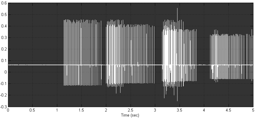
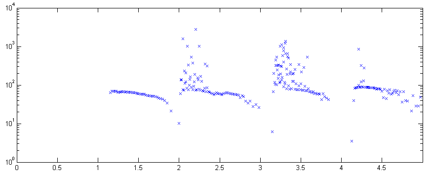
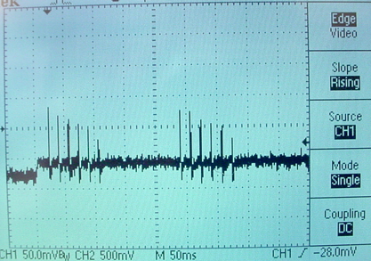
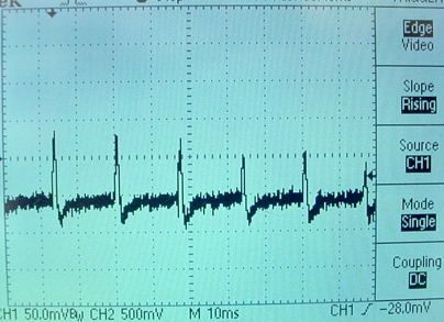
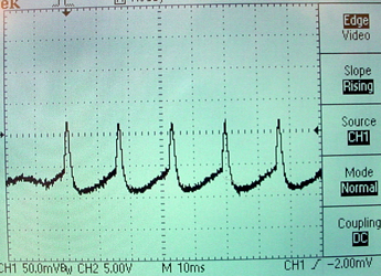
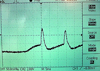
where the >>5 operator divides the value by 32 by shifting. If we monitor this program using the audio input of a computer and the Matlab DAQ toolbox, we can write a program to record spikes. The following images show the results of sweeping a light over the four photosensors. You can see the different amplitudes of units and the approximately exponential fall of spike rate in the second image.
Intracellular recording model using a state machine
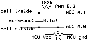
We built a dynamic clamp using a Atmel Mega32 microcontroller (MCU) to produce realistic current flows into a passive membrane capacitance. The circuit is shown below. There are two external connections, as there would be in a real cell. The MCU reads the differential voltage at A.1 and A.0 (membrane voltage) to control conductances. All voltages are produced by varying the current coming from the timer0 PWM output. The potentiometer is adjusted to make a resting potential of -90 mV. The potentiometer setting acts as the reference voltage for the ADC and for the external connections. Note that MCU ground must be isolated from the box that contains the circuit so that the external ground reference is the cell outside lead.
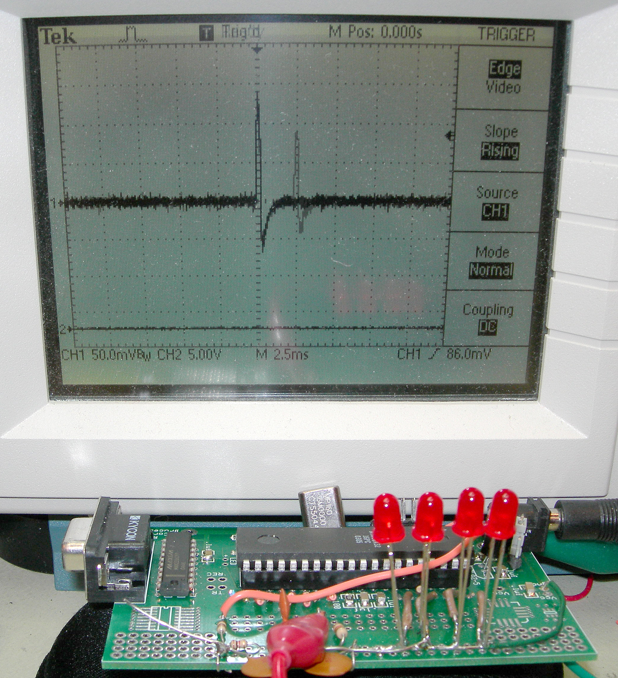
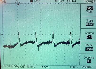
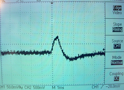
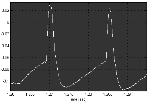
The first version of the MCU code written in Codevision C produces square-wave conductance changes set by a state machine. Resting potential is set at about -80 mV. During an action potential, the active sodium conductance turns full on for .75 mSec, then the active potassium conductance turns full on for about 1.5 mSec. The scope trace below shows stimulation with a constant current produced by a button push about one division from the left side of the screen. (Also supplied by the dynamic clamp). The expanded version to the right shows the exponential rise due to constant sodium conductance.
The code consists of an interrupt service routine (ISR) where most of the computation takes place and a main routine to set up parameters and intialize the ISR. It was convenient to use units of mV/4 for all constants and for the voltage read across the simulated membrane. On each cycle through the ISR:
A slightly modified version of the code softens the sodium conductance to make a more rounded action potential. This version also fixes a minor start-up instability. The conductance changes are still based on a threshold voltage and a fixed time course.
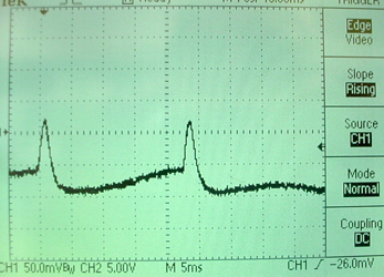
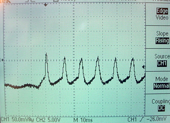
Modifying the state-machine code further allows for bursting. The bursting is produced by weaking the peak sodium current after a certain number of action potentials. Scope traces are shown below. The second image shows one burst.
Intracellular recording model using modified Hodgkin-Huxley model
The circuit is the same as in the previous section and the potentiometer is adjusted to a resting potential of -90 mV. The program uses the following model:
m = m∞

    h = h + (h∞-h)*dt/τh

   n = n + (n∞-n)*dt/τn
m∞, h∞ and n∞ switch between two states. They are each either one or zero depending only on the membrane voltage. The m∞ and n∞ values go to one when depolarized. The h∞ value goes to zero when depolarized. τh and τn are either fast or slow depending only on the membrane voltage. They are fast when the membrane is depolarized. Gna=maxGna*m*h. Since m is either one or zero it makes no sense to raise it to a power. Gk=maxGk*n4. Gna*(v-Ena) + Gk*(v-Ek) All arithmetic is done in 8:8 fixed point. Voltages are scaled so that the integer part of the fixed point number is mV/4. The model is updated 7800 times/sec.
Below are some traces at different levels of constant current injection.
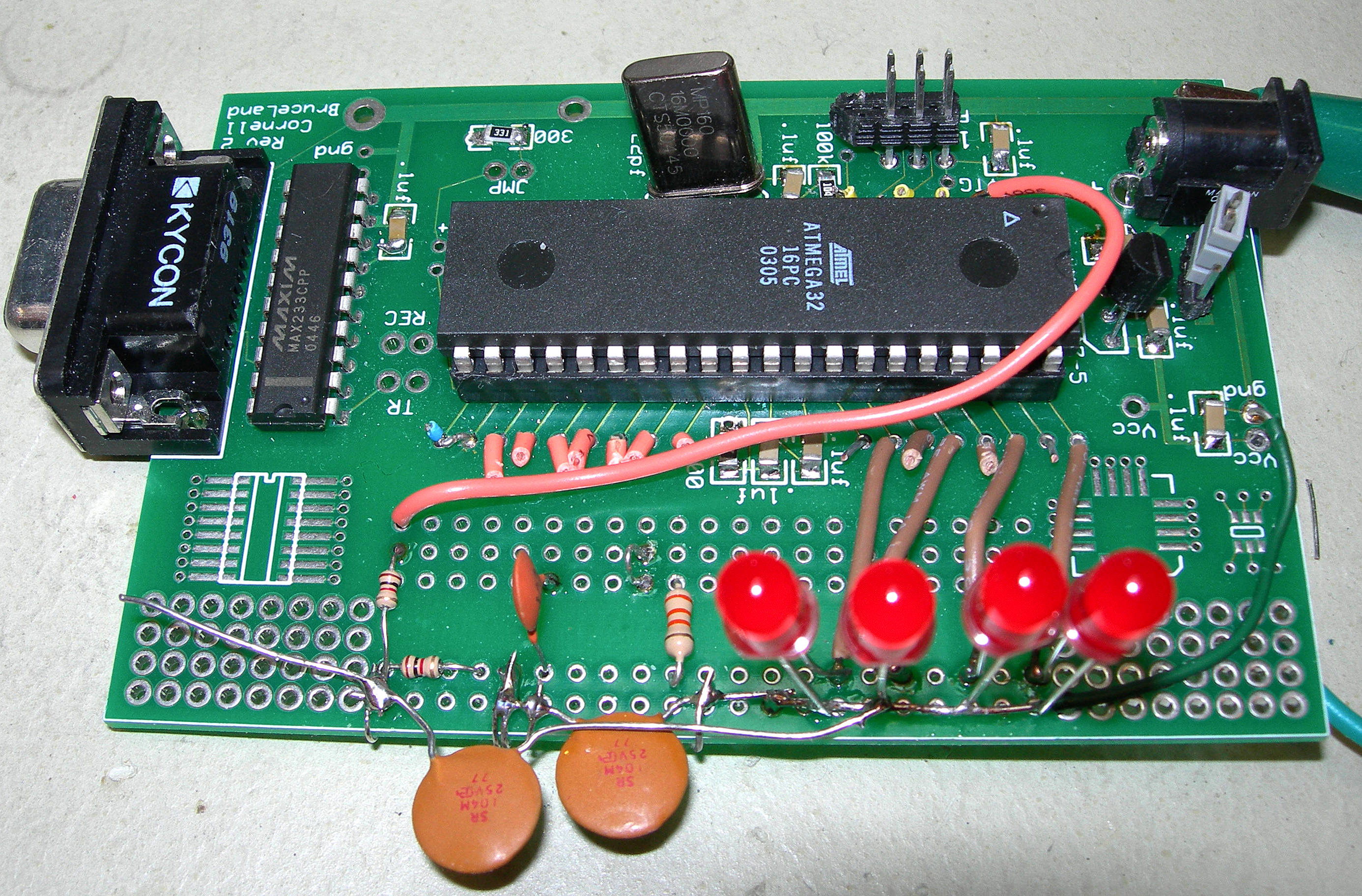
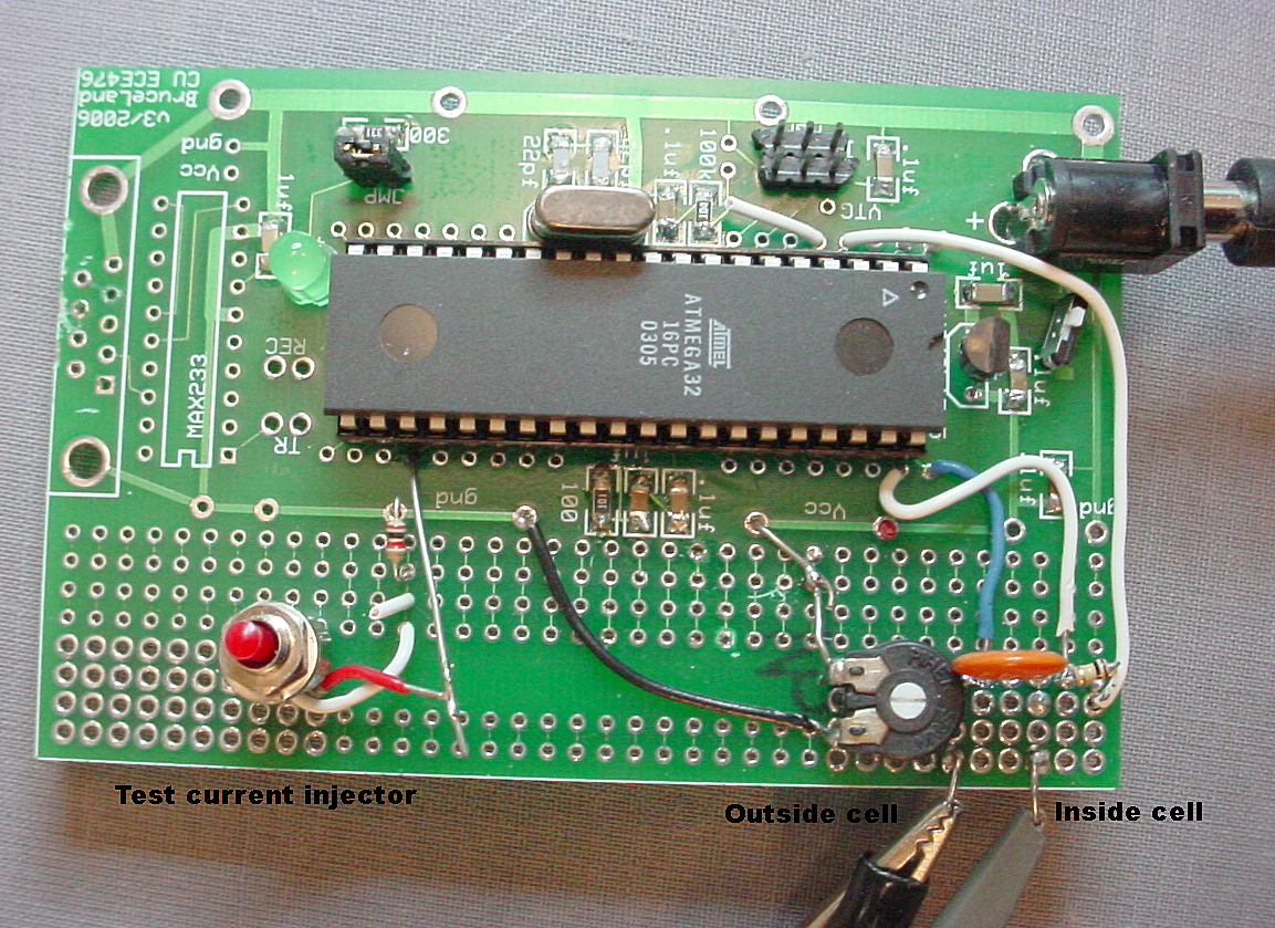
A slightly modified version of the program has somewhat slower h and n dynamics and runs on the standalone board. An action potential and the board are shown below. The resting potential adjusting trimpot is in the lower right, next to the membrane capacitor. There is a button to the lower left to inject a test current.
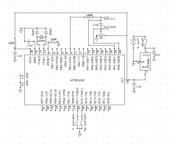
The full schematic is below. Note that ONLY two connections go to the outside world: CellIn and CellOut. Microcontroller ground must not be connected outside this circuit.
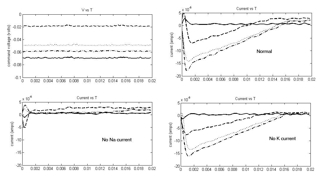
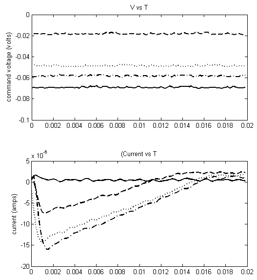
The following images are matlab figures under current clamp and voltage clamp recorded using the National Instruments USB-6008 interface. The current clamp used a simple voltage follower for recording. The voltage clamp circuit is shown below. There were two separate programs to make these images, one for current clamp and one for voltage clamp.

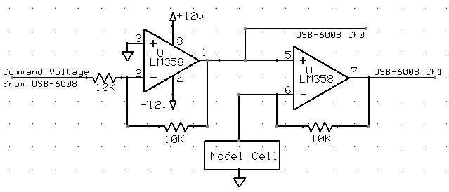
The voltage clamp circuit used is shown below. The command voltage inverter (first opamp) is necessary because the USB-6008 can only produce 0-5 volt output and this circuit required a negative clamp voltage. The matlab program performed the operation
(Ch1-Ch0)/10000 = (V1-V0)/Rfeedback
to estimate current.
Individual conductances can be inactivated in this version of the program. Shorting microcontroller pin C.7 to ground zeros the sodium current. Shorting microcontroller pin C.6 to ground zeros the potassium current. The next figure shows normal, suppressed soduim and suppressed potassium current conditions. The voltage step occurs at time zero to the value shown. Before the step, the volage was maintained at -100 millivolts.