Introduction
We needed hardware neural models for teaching neurobiology and electronics. We wanted models at at least two different levels:
The circuits below were simulated in Electronics Workbench and will be built as hardware models for students.
Analog conductance-level circuits
Maeda and Makino (1) show how to model a neuron using 3 transistors for a FitzHugh-Nagumo (FHN) type neuron (simplified from Hodgkin-Huxley formulation). The FitzHugh-Nagumo scheme replaces the fast Na current of the HH model with a simplified fast, depolarizing, activation process, and replaces the slow Na inactivation and slow, repolarizing, K current by a single slow inactivation process. By adding one more repolarizing process, modeled by two more transistors, they can produce a neuron with bursting behavior.
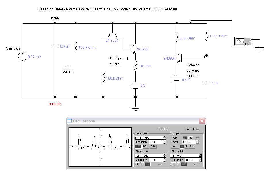
The circuit is show below for the FHN neuron. The circuit produces a constant train of simulated action potentials (AP) when a constant current is applied. The Electronics Workbench file is here. Note that the amplitude of the simulated action potential is much larger than that of a physiological neuron. Simulated AP amplitude is around 5 volts, while in real life the AP amplitude is around 100 mV.
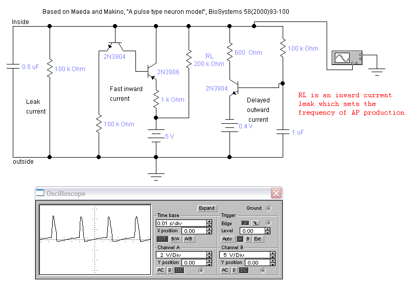
The neuron can be made to oscillate without an external current source by adding RL shown below. The resistor acts as an inward current leak. The usefulll range of RL is about 25 kohms (fast oscillation) to around 250 kohms.
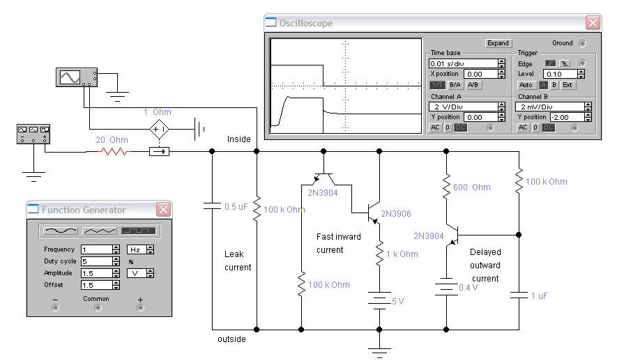
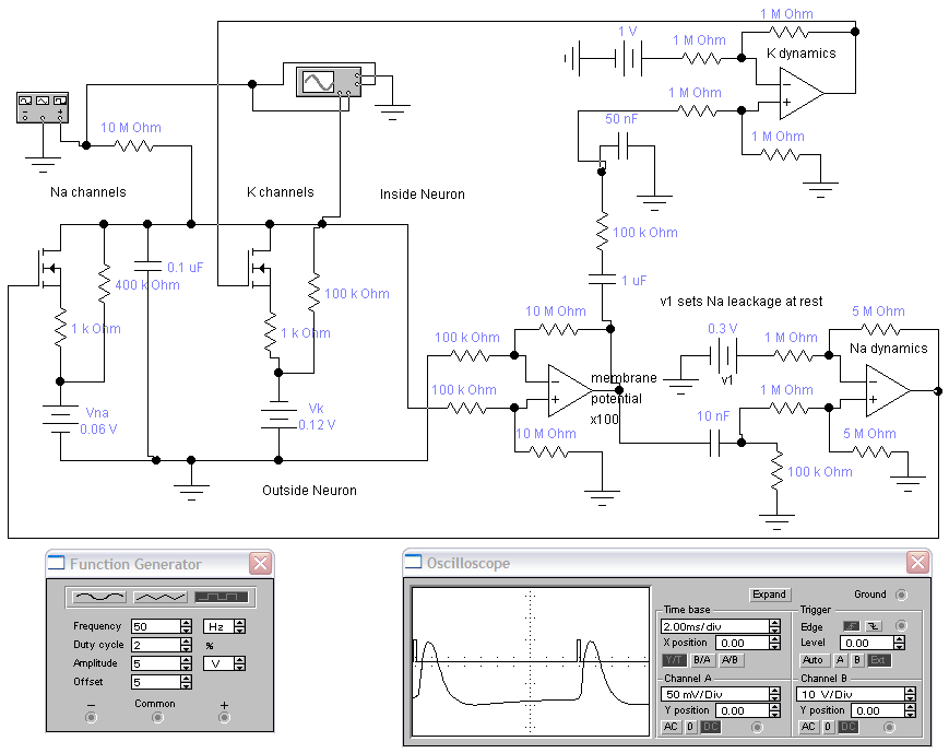
It is easy to voltage clamp these model neurons. The image below shows a 3 volt step applied from resting potential. A transient inward current is seen, followed by an outward current. EWB file.
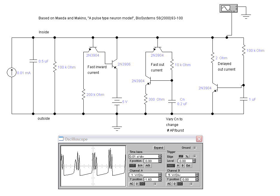
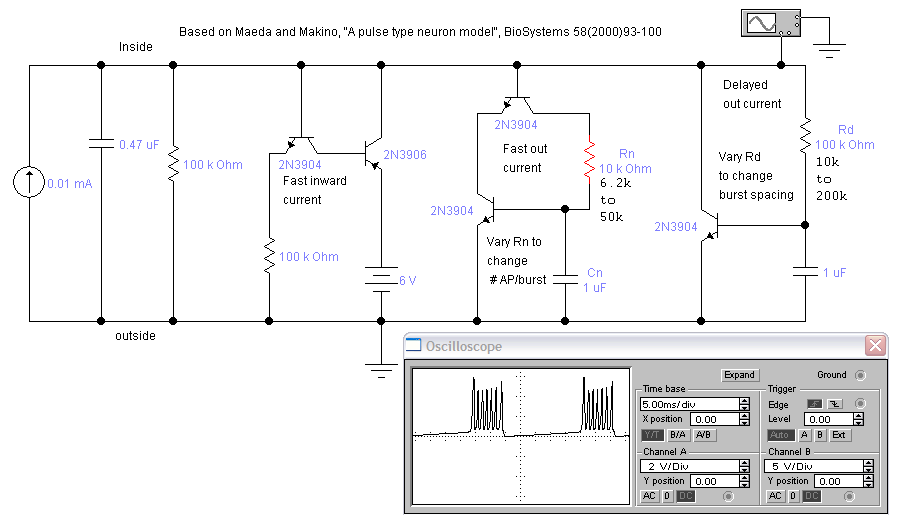
The circuit is show below for the FHN neuron, extended with an extra conductance process. The circuit produces a constant train of simulated AP bursts when a constant current is applied. The Electronics Workbench file is here.
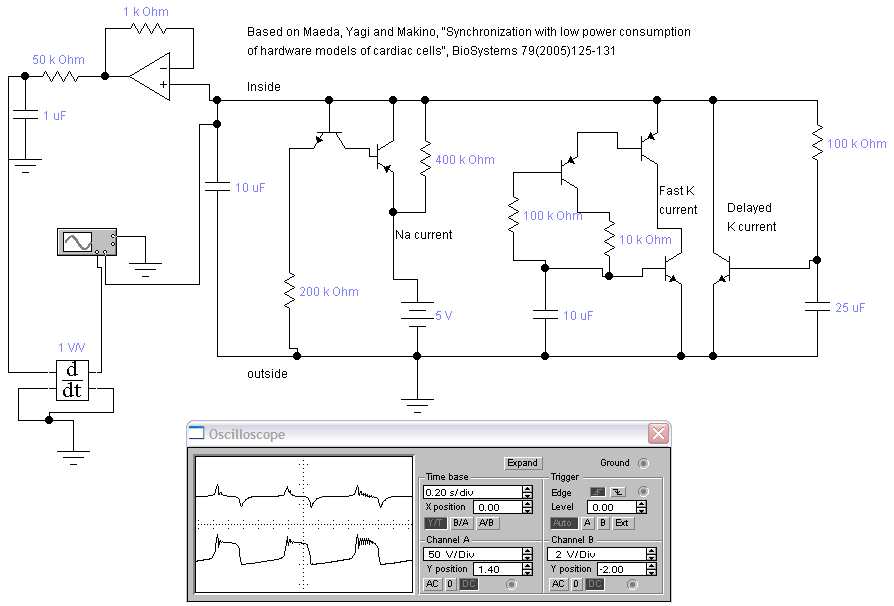
Maeda, Yagi, and Makino (2) extend the model to include heart cells. They slightly modified one of the repolarizing processes to make a plateau potential. The circuit show below shows two traces. The bottom trace is membrane potential, the top is the deritivive, which is a simple approximation of an ECG. The Electronics Workbench file is here. Be sure to set the integration method to Gear in the menu item
Analysis...Analysis Options...Transient. The example below uses the default trapzoidal method, which causes spurious oscillations.
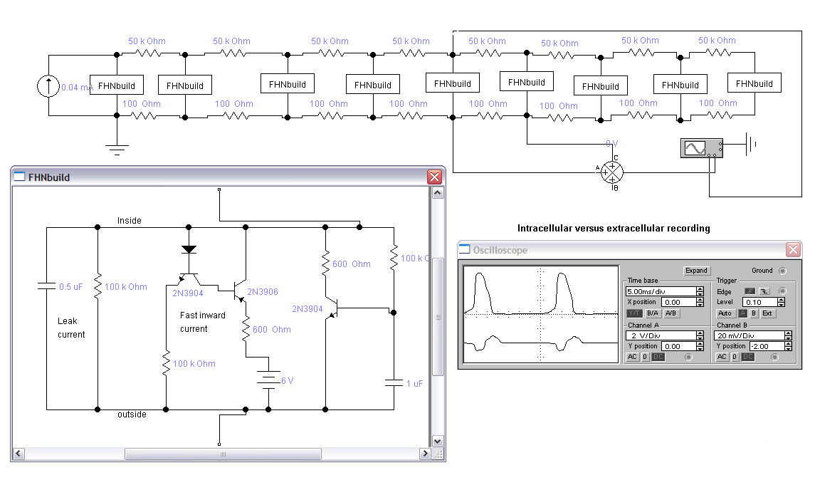
By turning one of the neurons into a macro (FHNbuild below), we can build an axon to investigate extracellular versus intracellular recording. The 50 kohm resistors model the axonal lumen. The 100 ohm resistors model the bath saline. The subtractor just below the axon simulates a perfect differential amplifier. Note that the voltage scale on the bottom (extracellular) trace is 100 times more sensitive than the top trace. The specific model built is decribed below in the Construction section. The Electronics Workbench file is here.
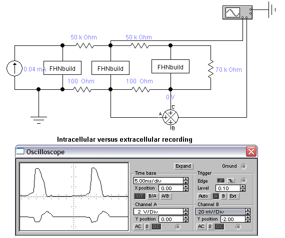
As few as 3 sections, terminated with a passive load, can be used as a teaching model.
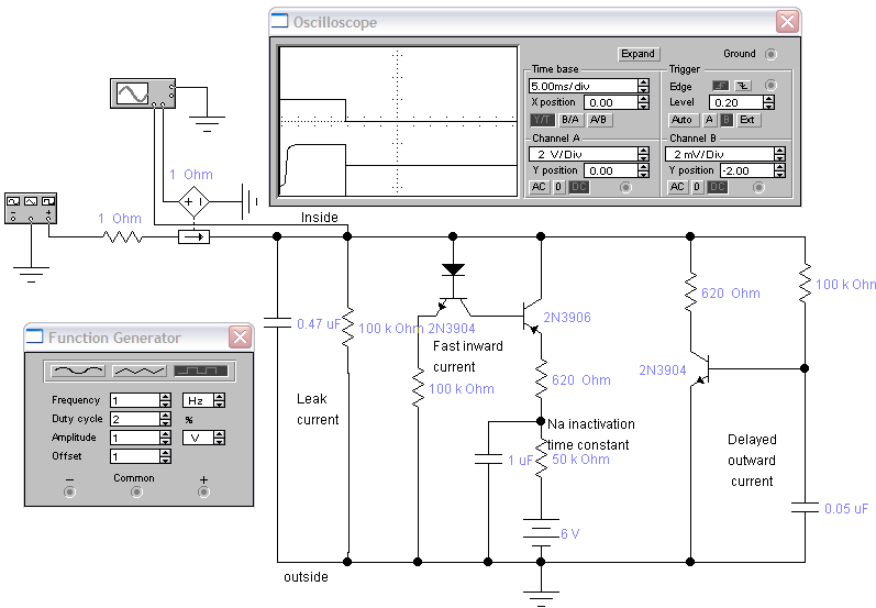
The basic FHN models don't have an explicit sodium inactivation, but for teaching voltage clamp techniques, it would be nice to have this process represented. The following circuit uses an RC combination on the power supply to the fast inward current to limit the current to a short burst. The length of the burst is determined by the size of the capacitor, here 1uf, and the membrane resistance. The refractory period is determined by the RC time constant, here 20 mSec. In clamp mode, if you change the 620 ohm resistor in either the fast inward or delayed outward current to 1 Mohm, then that current is essentially eliminated, simulating a selective block of the approriate channel. The two currrents can thus be seen separately. Workbench file.
Conductance Models based on Guy Roy's NeuroFET (3)
These models use analog computation, combined with N-channel, enhancement-mode, field-effect transistors, to simulate conductance changes in the membrane. The circuit is scaled so that the timing and magnitude of the conductance changes (and voltage changes) are biologically realistic. The battery V1 sets the leakage through Na channels at resting potential. A more positive value stabilizes the membrane, while more negative can cause oscillations. Electronics Workbench file.
Model Synapses
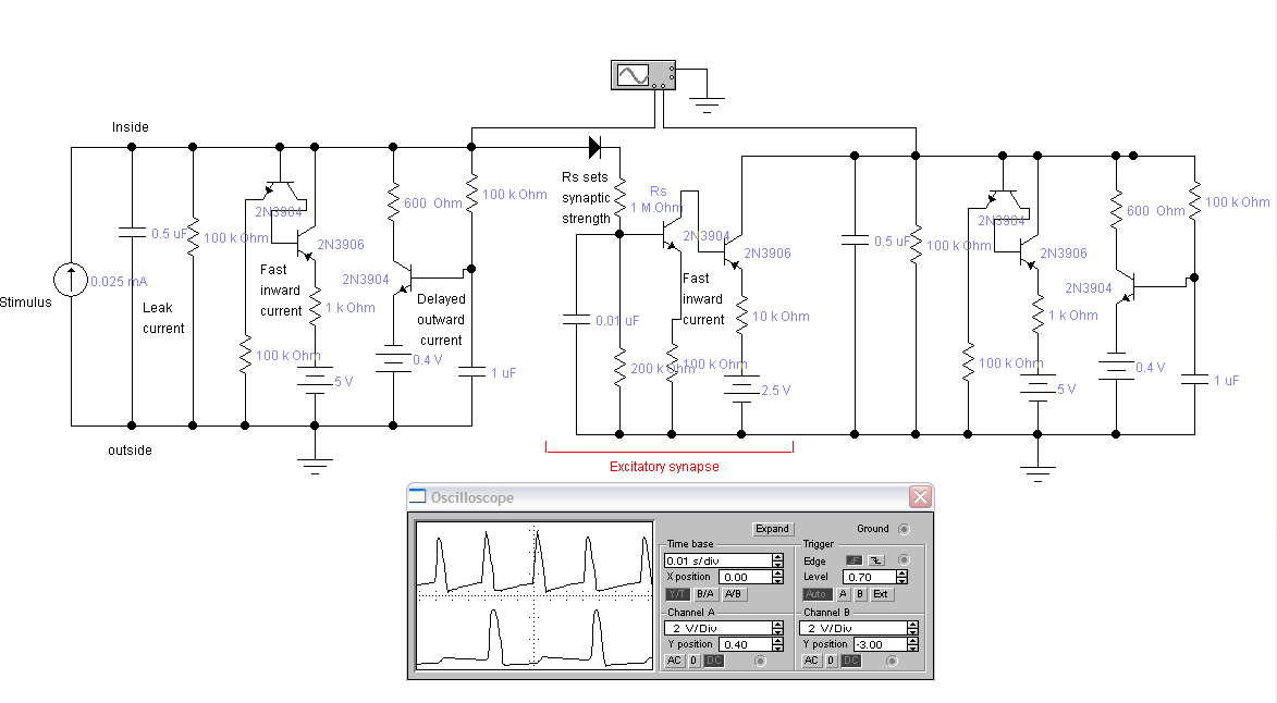
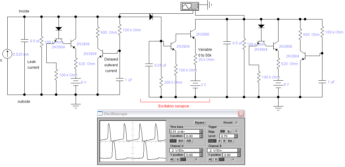
Modifying the depolarizing process channel to depend on presynaptic voltage (and changing the reveral potential) makes an excitatory synapse. Top trace is the presynaptic cell. Bottom trace shows postsynaptic cell with EPSP and AP. The diode in the synapse represents the isolation of the presynaptic side due to transmitter release. The Electronics Workbench file is here.
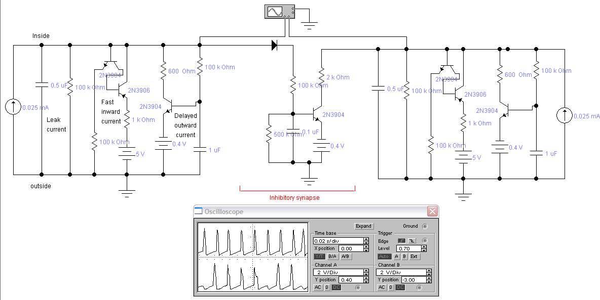
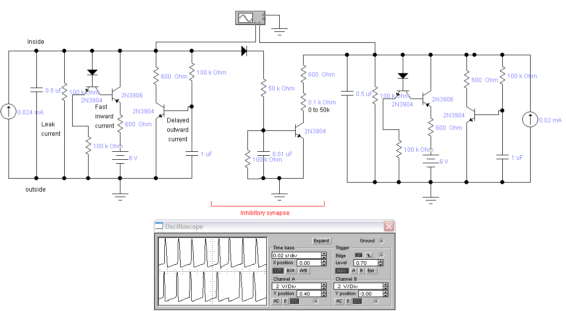
Modifying the repolarizing process channel to depend on presynaptic voltage makes an inhibitory synapse. Top trace is the presynaptic cell. Bottom trace shows postsynaptic cell with IPSP and AP. Note that this inhibitory synapse exhibits shunting as well as hyperpolarization. The Electronics Workbench file is here.
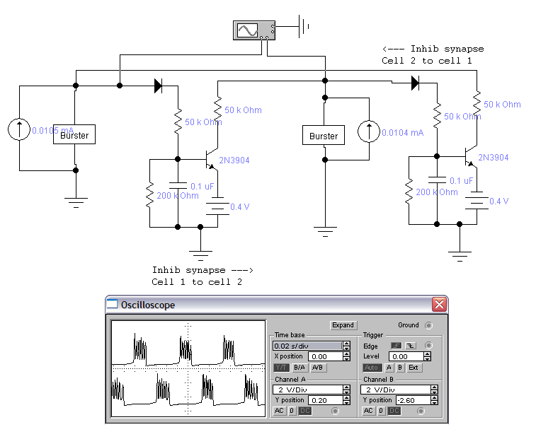
A burster cell was turned into a macro, then two of them were connected through inhibitory synapses. By adjusting the strength and time constant of the synapse, you can get alternate bursting. The Electronics Workbench file is here.
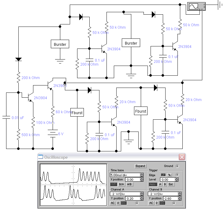
With four bursters, connected as two sets of alternate bursters, you can get 2:1 locking by adding an excitatory synapse between the two sets. The faster set was adjusted to have a natural burst rate just slightly slower than 2:1 lock. The excitatory synapse adds a little extra current to lock the frequency. The Electronics Workbench file is here.
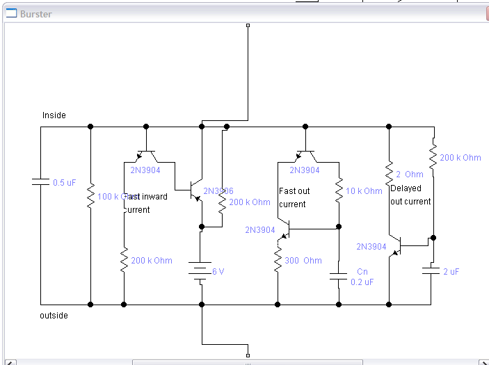
The burst macro:
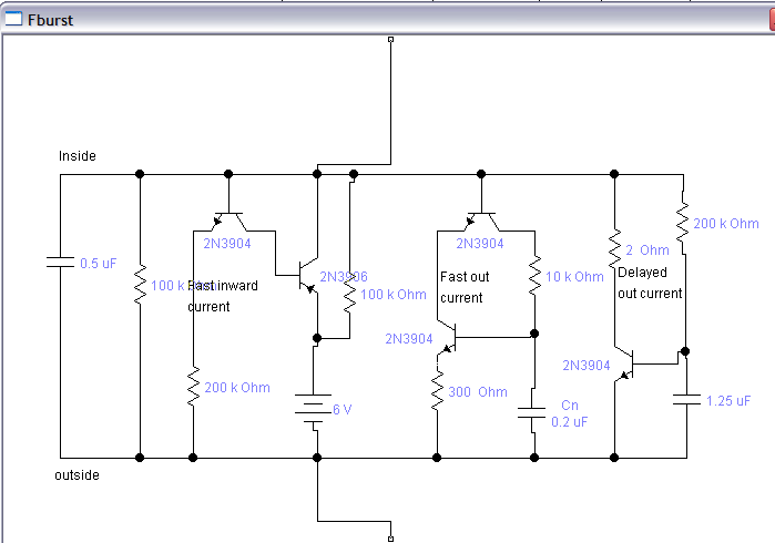
The Fburst macro:
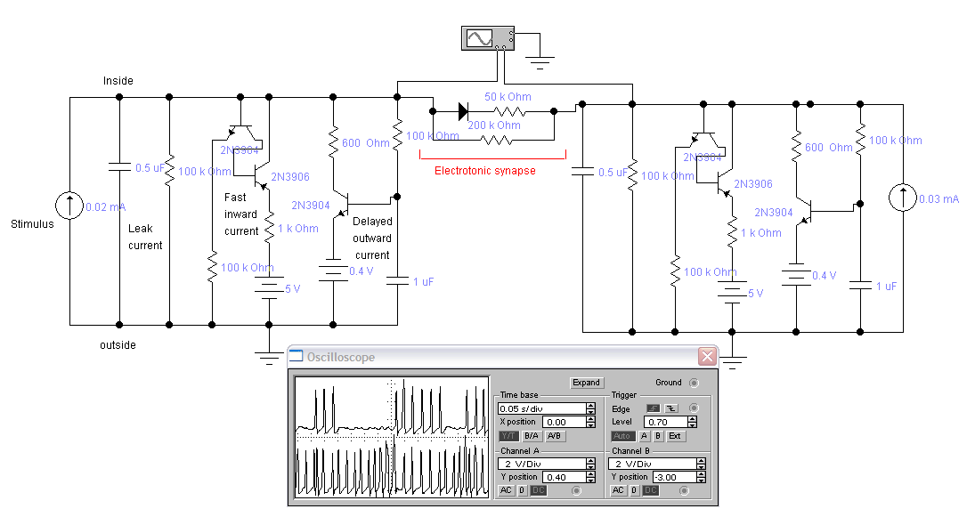
Adding a diode and resistors between the two cells results in an electrotonic connection with a stronger connection from left to right. The traces show a very complex interaction between the two cells. Note that any given electrotonic synapse can be rectifying in either direction, or not at all. The Electronics Workbench file is here.
Integrate-and-fire circuits
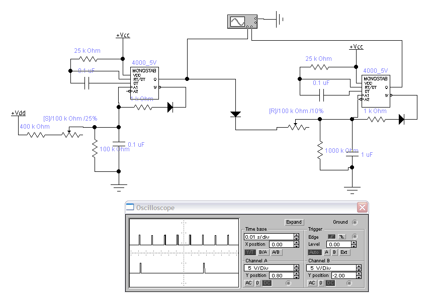
The circuit below uses monostables (e.g. 74HC123) as integrate and fire (IF) neurons. The Q output is the AP pulse. The W output is an inverted AP pulse. The diode to the W output discharges simulated membrane capacitance when an AP occurs. The 25k/0.1 uF components attached to RT/CT and CT inputs set the length of the AP pulse. The neuron on the left is driving the neuron on the right with an excitatory connection. The Electronics Workbench file is here.
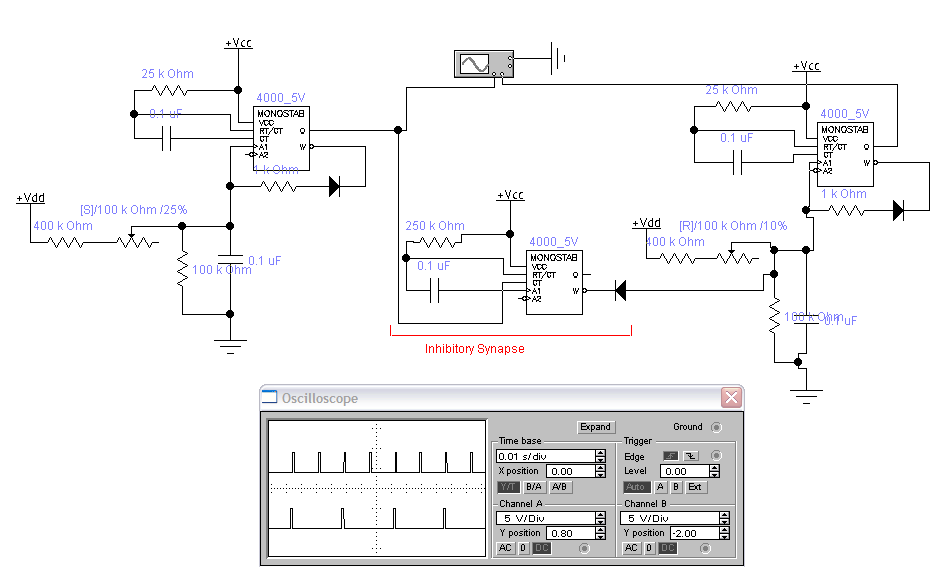
The circuit below connects 2 IF neurons with an inhibitory synapse. The monostable was added to stretch the pulse and invert it. A better version of an excitatory synapse (than the one shown above) would be to use the Q output of the synaptic monostable as the input to the second cell through a diode which allows current to from from the Q terminal to the second cell's input capacitor. The Electronics Workbench file is here.
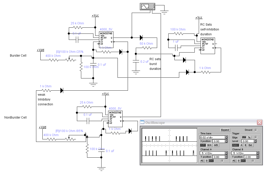
The following circuit implements a IF burster by using a second monostable to inhibit the first one. The top two monostables are the burster. The bottom monostable is an weakly inhibited non-burster. The Electronics Workbench file is here.
Construction
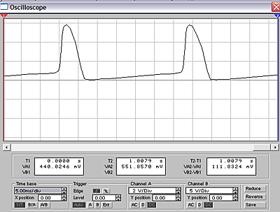
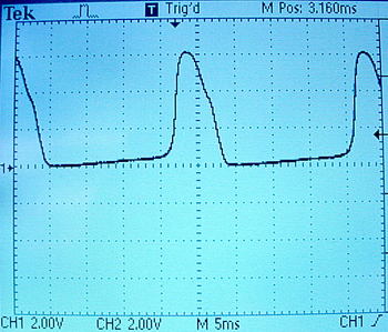
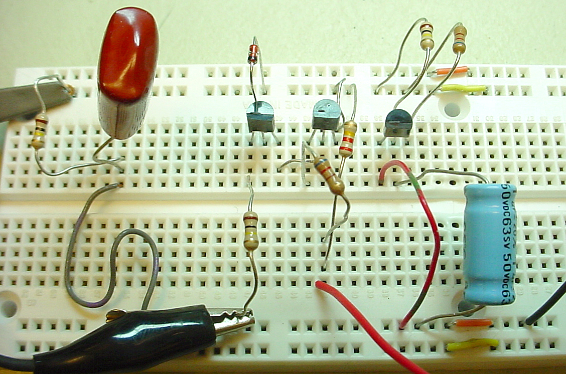
To actually build one of the Maeda neurons, it is handy to simplify the power supplies so that only one battery is needed. Elimanating the simulated potassium battery required changing the sodium current threshold by adding a diode. The battery voltage was changed to 6 volts to make it easier to use lithium batteries. The RL resistor allows the circuit to act as a pacemaker. Replacing RL with a CdS photoresistor makes a photosensor with output frequency related to light intensity. Lower resistance is a faster pacer. The userful range of RL is about 25 kohm to 450 kohm. The expanded simulated scope image should be compared with the photograph of the real scope screen. The Electronics Workbench file is here. A picture of the white board prototype is included below.
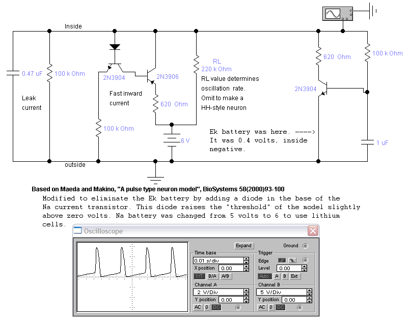
Expanded simulation scope on the left and output from the real circuit.
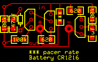
A first hack at a curcuit board is shown below. Transistors are (from left to right) 2N3904, 2N3906, 2N3904. The diode is a 1N914. A battery holder is mounted on the back of the board. the two vias on the left side of the board are the only two connections to the outside world. Top left is inside the cell, bottom left is outside. The resistor marked *** sets the pacemaker rate. Omitting this resistor makes the circuit more like a squid axon element. ExpressPCB file.
Parts list. All part numbers are Digikey:
Tentative burster to build (EWB file):
Tentative Excitatory Synapse to build (EWB file):
Tentative Inhibitory Synapse to build (EWB file):
References