Introduction
The nervous systems of animals (and humans) are complex electrochemical machines.
The electrophysiological study of a nervous system treats the system as an electrical
device built of very complex, non-linear elements called neurons. To understand
the function of a neuron, or network of neurons, one must probe the system with
pulses and record what happens. For instance, a researcher might apply pulses
to a nerve and measure muscle contraction. The device to be described here allows
a researcher to inject electrical pulses into neural tissue. The biological
jargon-term for this device is a "stimulator". The output of the stimulator
must:
Ten years ago, a stimulator was an analog device built with 555 timers, switches and potentiometer knobs. The analog version was limited to a few waveforms, typically one or two pulses of the same duration separated by a variable delay and recurring at a fixed rate. Isolation was achieved by using optocouplers and batteries. Now it makes more sense to use a microcontroller to generate the pulses and a PC to generate the user interface. The microcontroller can guarantee a real-time response, while the PC has tools to produce a convenient user interface. Since we intend to use these stimulators in a teaching context, we wanted to eliminate all batteries from the isolator section. Teaching makes large demands on batteries because of the daily use and the unfamiliarity of the equipment to the students. The combination of ubiquitous PC for control, microcontroller for pulse generation and a novel isolation circuit makes the circuit cost-competitive for student laboratory use.
The following block diagram summarizes the stimulator circuit. A single transistor
is used to interface RS232 levels (receive only) to the UART input of the microcontroller.
A Matlab program running on the PC sends simple commands to the microcontroller
to set up pulse timing and amplitude. The microcontroller produces a pulse-width
modulated (PWM) output proportional to the desired amplitude. The PWM output
is lowpass filtered and converted to a current to drive an optocoupler. The
optocoupler has a photoFET output which, when used in a voltage divider, (see
full schematic) produces a voltage output which is almost linear (+/-5% full
scale) with the PWM input. Power for the isolator is controlled by a timing
pulse from the microcontroller that rapidly gates a transformer-isolated, 14
pin DIP, DC-to-DC converter. Pulse rise and fall times time are about 50 microseconds,
much faster than the bandwidth of the neurons being stimulated. The circuit
can provide about a watt to the output, sufficient for most experimental setups.
The microcontroller emits a synch pulse at the start of each pulse train repetition.
Pulse train repetition is either periodic (and set by the user interface) or
manually triggered.
Project Details
Specifications
An electrophysiological stimulator needs to produce a (possibly repeating) pulse train. Pulses are acceptable for most research since the active elements of the nervous system, called neurons, are charge integrators. Said differently, the details of the waveform are unimportant as long as the product of average current and time reach some threshold value. The stimulator to be described here can:
Figure 1 summarizes the waveforms generated. The synch pulse is emitted from
a port pin with duration of about 16 machine cycles (2 microseconds). The synch
pulse is typically used to trigger an oscilloscope. The 'repeat time' shown
represents the time between pulse trains, if the GUI sets the mode to repeat.
The main output is the pulse train which consists of a series of variable amplitude
pulses of a specified duration and delay.
AVR Software
An Atmel AVR AT90s8515 was used to control the timing of pulses and pulse amplitude as well as the serial command interface from the PC. All programming was done in CodeVision C. The output circuitry controlled by the AT90s8515 implements the pulse generation and electrical isolation.
The C program running on the AVR (see Appendix A) sets up i/o functions and state variables, then defines a main loop and one interrupt service routine (ISR). Details follow:
g start generating pulses in repeat mode, enable pushbutton
in manual modes stop generating pulses in repeat mode, disable pushbutton
in manual modemm set manual modemr set repeat modep number amp duration spacing repeat set parameters.p 3 50 10 20 1000GUI software on the PC
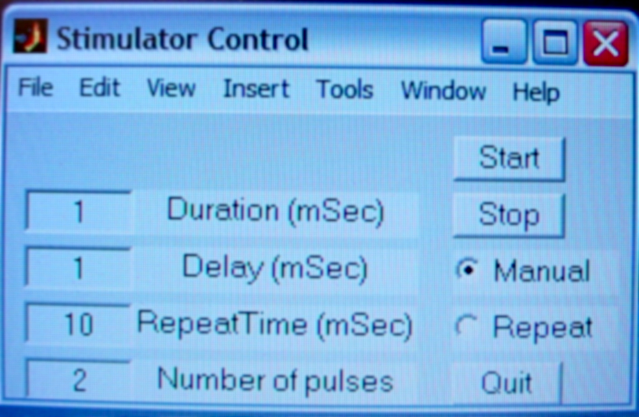
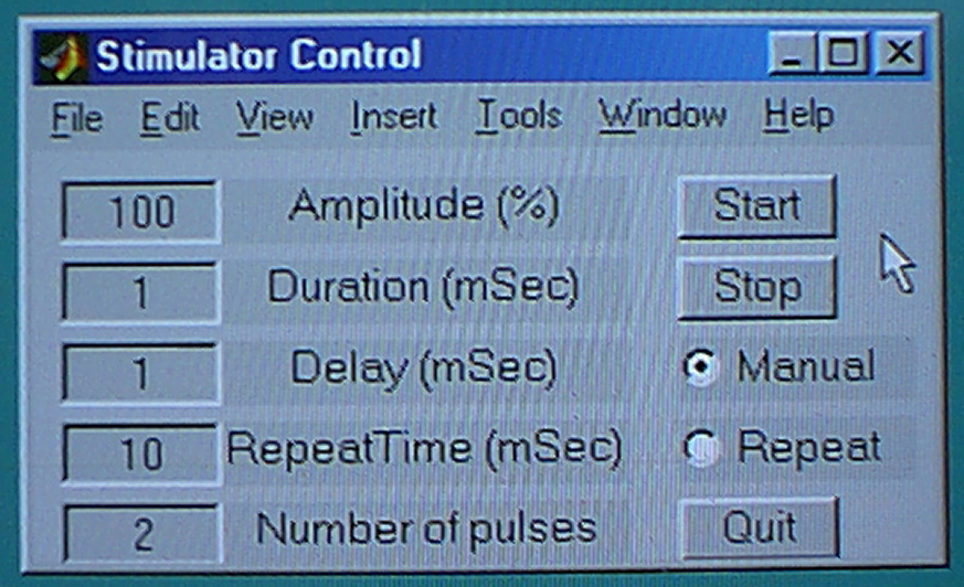
A Matlab (mathworks.com) program running on the PC was written to provide the GUI and provide commands via the serial interface (see Appendix B). For this simple control application I defined five edit fields and a few pushbuttons (see screen dump in Appendix B) to control the stimulator. The program structure is simple: Define the controls, then enter an event loop and wait for controls to be touched. Each of the controls has a "callback" function that I used here for range checking and for setting an execution flag. The main loop mostly formats strings to send to the AVR, based on the numerical contents of the various edit fields. The GUI program handles unit conversion, and locks out changes in the parameters during pulse train generation.
Circuitry
As shown in Figure 3, the AT90s8515 was connected in a standard fashion with an eight MHz crystal and with the reset line pulled up with a 100kW resistor. A diode-clamped NPN transistor was used to invert and level-shift the RS232 signal from the PC. The manual trigger pushbutton (normally open) was connected from portD.2 to ground, with the internal pullup resistor turned on. An 8 MHz clock yields an overflow time of 32 microseconds for timer 0, which becomes the resolution of the pulse width. The GUI software rounds all pulses to 0.1 millisecond, or 4% greater than 3 overflow times. Thus, even short pulses have a relative accuracy of 4%.
Two outputs from the AVR are used to control aspects of the stimulator pulses. The timer 1, channel A, PWM output (port D.5) controls the pulse amplitude. The port pin D.3 is toggled by the timer 0 ISR to control pulse timing. PortD.4 is the synch pulse output for external connection to an oscilloscope or other recording device.
The PWM output is low-pass filtered with a simple RC circuit with a time constant of 0.01 second. Typically, amplitude would be changed only between pulse trains, so 0.01 seconds is fast enough. The filtered voltage varies from 0-2.5 volts, depending on the PWM setting (0-128). The full PWM range of 0-255 was not used because the opamp feedback circuit cannot follow inputs above about 3 volts (due to voltage drops across the transistor and optocoupler LED), while keeping the current constant through the optocoupler. For a 0-2.5 volt input, the opamp/transistor feedback loop produces 0-30 milliamps through the optocoupler LED.
Timing control for the pulses operates by gating the Burr-Brown/TI DCP010515D DC-to-DC converter using the "SYNCH-in" pin. This scheme has the advantage of zero offset error between pulses, which is important for tissue and electrode integrity. The DC-to-DC converter is turned on by floating its SYNCH-in pin and turned off by grounding the pin. The 4066 quad CMOS transmission gate is used as an inverter and as a switched ground connection to the converter SYNCH-in pin.
Together the DC-to-DC converter and the H11F1 optocoupler isolate the output
pulse from all external circuitry. Their effect is to act as a rapidly switched
voltage source and a more slowly set voltage divider to produce and attenuate
the final output pulse. The 20KW resistor across the output loads the DC-to-DC
converter to help with voltage regulation. The H11F1 and the 10kohm resistor
act as a voltage divider.

Performance
The GUI and 8515 can be started in any order because the 8515 waits for a command from the GUI, and the GUI sends only self-contained commands. Of course, if you cycle the 8515 power while it is actually receiving a command, it may end up in an indeterminate state.
Actual measured pulse rise times were around 50 microseconds, but varied somewhat
with amplitude from 40 to 70 microseconds. Pulse duration and delay times were
within the expected 4% maximum error for a short pulse. Figure 4 shows the linearity
of the amplitude control. The largest variation from the best-fit straight line
is about 5% of full output voltage.
Photographs
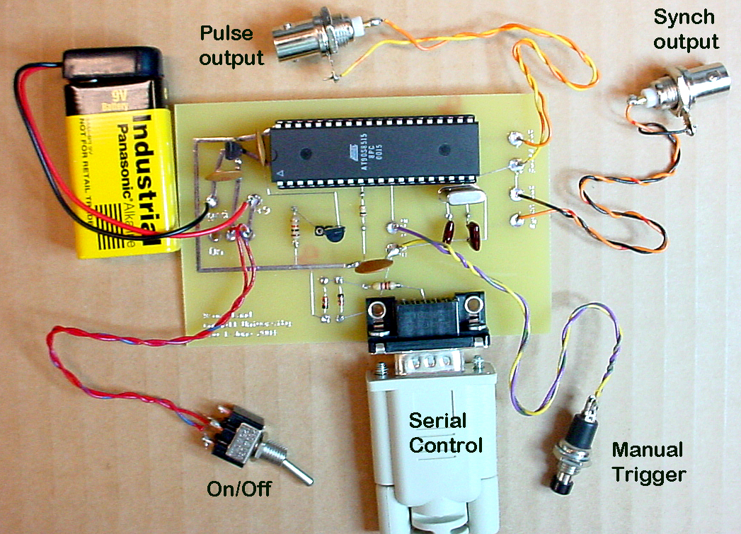
A photograph of the whole stimulator shows that the device was built on two
circuit boards. This allows a biological researcher to place the noisy microcontroller
away from the experiment, while allowing the isolated pulse output to be as
near the experiment as possible.
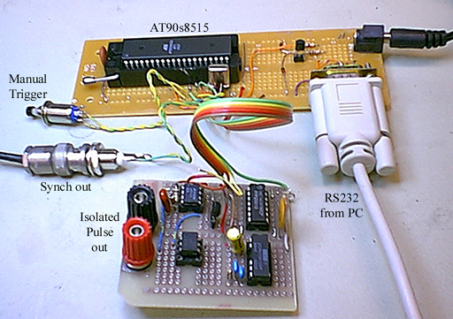
A closeup of the isolator output with clip leads attached.
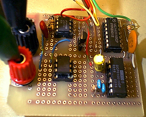
A closeup of the AT90s8515.

A photograph of the oscilloscope screen shows the synch pulse on the top channel (in the center of the screen) and a train of two pulses on the bottom channel. Pulse length was set to 2 milliseconds and delay was set to 3 milliseconds. Gain settings are shown at the bottom of the frame.

Conclusion
This microcontroller-driven stimulator provides a flexible and inexpensive
solution for our biology teaching needs. We intend to deploy these stimulators
in student labs by next spring.
Appendix A. AT90s8515 C program
//Stimulator version 2.0
/*
Pulse train:
1-255 pulses
0-4 sec pulse duration
0-4 sec pulse spacing
0-4 sec train repeat time
0-30 volt amplitude

Pulse output is port D.3
Synch output is port D.4

Trigger is either manual or periodic
Manual trigger is port D.2

timer 0 ISR generates pulse timing
timer 1 generates PWM for amplitude control on pin OC1A (D.5)
  continuously so lowpass filter can average it
main loop handles parameter setting and rs232 comm
*/

#include < 90s8515.h>
#include < Stdio.h>
#include < delay.h>
#include < stdlib.h>
#include < math.h>

#define begin {
#define end   }

//input parameters
unsigned char num;	//number of pulses
unsigned int dur;	//pulse duration
unsigned long durL;	//holds duration string for float convert
unsigned int delay;	//pulse spacing
unsigned long delayL;	//holds delay string
unsigned int rep; 	//pulse train repeat time
unsigned long repL;	//holds repeat time string
unsigned int amp;	//pulse amplitude 0-255

//state variables
unsigned int elapsedT;	//running stimulus time
unsigned int nextT;	//next event time
unsigned char mode;	//manual or repeat  'm' or 'r'
unsigned char pulseon;	//state machine variable 1 or 0
unsigned char currentpulse;//current pulse num
unsigned char starting;	//indicates first time thru ISR
unsigned char cmd;	//serial command character

float Conversion;	//converts mSec to units of 64 microSec

//#pragma savereg-
//********************************************
//timer 0 overflow ISR
interrupt [TIM0_OVF] void t0_overflow(void)
begin

   //check for starting and emit synch pulse, reset time
   if (starting)
   begin
      PORTD.4 = 1;	//start synch pulse output
      starting = 0;	//on next ISR we won't be starting
      elapsedT = 0; 	//relative to pulse train start
      pulseon = 0;	//starts in the off state
      nextT = delay;	//next deadline time
      currentpulse = 0; //the pulse number
      PORTD.4 = 0;	//end synch pulse
   end

   else  //not starting
   begin
      elapsedT++;	//all times are in 't0 ovfl tick units'

      //at end of pulse train:
      //check for manual mode and kill timer
      //otherwise set starting back to 1 for next train
      if (elapsedT == rep)
      begin
         PORTD.3 == 0; 		//kill the output pulse just in case
         if (mode == 'r')
            starting=1;		//get ready to restart
         if (mode == 'm')
            TCCR0=0;   		//kill this ISR
      end

      else if (elapsedT == nextT)
      begin
         //have we putput all of the pulses?
         if (currentpulse < num)
         begin
            if (pulseon)
            begin	//turn off the pulse
               pulseon = 0;
               PORTD.3 = 0;
               nextT = elapsedT + delay;
            end
            else
            begin	//turn on the pulse
               pulseon = 1;
               PORTD.3 = 1;
               currentpulse++; //inc the pulse cout
               nextT = elapsedT + dur;
            end //pulseon else
         end

         else   //(currentpulse==num) so the train is done
         begin
            PORTD.3 = 0; //kill the last pulse
            nextT = 0;	//impossible time marker so next match is rep
         end

      end //if elapsedT

   end //else not starting

end  //ISR

//
//*********************************************
//#pragma savereg+

void main(void)
begin

  //serial comm setup (no interrupts)
  UCR = 0x18 ;
  UBRR = 51; //25 ;   4 MHz value
  //putsf("\rStimulator 2.0 copyright Cornell University\r");

  //timer 0 setup
  TIMSK = 0x02 ;	//Timer 0 ovfl enable
  TCCR0 = 0;		//Timer 0 is off

  //timer 1 setup (rest of setup is in ISR)
  TCCR1B = 0;		//Timer 1 is off

  //port D setup
  DDRD.2 = 0 ;		//port D.2 is trigger input
  PORTD.2 = 1;		//turn on D.2 internal pullup
  DDRD.5 = 1 ;		//port D.5 is PWM output
  DDRD.3 = 1;		//port D.3 is main pulse
  DDRD.4 = 1;		//port D.4 is synch pulse

  //Convert 10*mSec to units of 64 microSec
  //                            32
  Conversion = 1000.0/32.0/10 ; // 1000.0/64.0/10 ;

  //turn on all interrupts
  #asm
    sei
  #endasm

  /*main event loop
  two events:
    serial command input
    --s stop
    --g go
    --p set parameters  number,amplitude,dur,delay,rep
    --m set mode manual/repeat
    starting pushbutton in manual mode
  */
  while(1)
  begin
    //if manual, check button D.2 for a trigger (active-low)
     if (mode=='m' && PIND.2==0)
     begin
  	TCNT0=0;
  	TCCR0=1;
  	starting=1;
  	//debounce the switch and wait for release
  	delay_ms(50);
  	while(PIND.2==0){};
  	delay_ms(50);
      end  //pushbutton event

    //check USR for a valid character and get it
    if (USR.7==1)
    begin
       cmd=getchar();
       switch (cmd)
       begin
          case 's':
             //to stop, terminate timer ISR and kill any output
    	     TCCR0 = 0;	 //turn off timer 0
    	     PORTD.3 = 0;  //and kill any leftover pulse
             break;
          case 'g':
             if (mode=='r')
    	     begin
       		TCNT0=0;  	//zero the clock
       		TCCR0=1;  	//and start it
       		starting=1;	//flag to tell ISR to start new pulse train
      	     end
      	     //putsf("running\r");
      	     break;
          case 'p':
             //putsf("\r\n#, amp, dur, delay, rep\r") ;
    	     scanf("%d%d%d%d%d", &num, &, &durL, &delayL, &repL) ;
    	     //printf("%d%d%d%d%d\r\n", num,amp,durL,delayL,repL) ;
    	    //convert time units
    	    dur = floor(durL*Conversion+0.5);
    	    delay = floor(delayL*Conversion+0.5);
    	    rep = floor(repL*Conversion);
    	    OCR1A = 256-amp;     //loads PWM duty cycle
    	    TCCR1B = 1;		//turn on PWM
            TCCR1A = 0xc1;  	//8-bit, inverted PWM mode
            TCNT1 = 0;		//start at zero to set phase
    	    break;
          case 'm':
             mode=getchar();
             break;
          case 'r':
             mode=getchar();
             break;
       end //switch
    end	 //if (USR==1) serial event handler
  end //while(1)
end //main
Appendix B. PC Matlab program and GUI screen dump
% Stimulator GUI

%clean up any leftover serial connections
clear all
fclose(instrfind)

%open a window
figure('position',[700 550 280 128],...
    'name','Stimulator Control',...
    'numbertitle','off')
clf

%open a serial connection
s = serial('COM2',...
    'baudrate',9600);
fopen(s)

%define the quit button
x=200; y=0; w=50; h=20;
exit=0;
quitbutton=uicontrol('style','pushbutton',...
   'string','Quit', ...
   'fontsize',12, ...
   'position',[x,y,w,h], ...
   'tag','stimcntl',...
   'callback','exit=1;close;');

%define the amplitude editable text field
x=10; y=100; w=50; h=20;
ampnow=0;
ampCtl=uicontrol('style','edit',...
   'string','100', ...
   'fontsize',12, ...
   'tag','stimcntl',...
   'position',[x,y,w,h],...
   'callback',[...
        'v=str2num(get(ampCtl,''string''));'...
        'if (v<1);set(ampCtl,''string'',num2str(1,''%6.1f''));end;'...
        'if (v>100);set(ampCtl,''string'',num2str(100,''%6.1f''));end;'...
        'ampnow=1;'...
        ]);
uicontrol('style','text',...
   'string','Amplitude (%)',...
   'fontsize',12, ...
   'tag','stimcntl',...
   'position',[x+w,y,125,h]);

%define the duration editable text field
x=10; y=75; w=50; h=20;
durCtl=uicontrol('style','edit',...
   'string','1', ...
   'fontsize',12, ...
   'tag','stimcntl',...
   'position',[x,y,w,h],...
   'callback',[...
        'v=str2num(get(durCtl,''string''));'...
        'if (v<.1);set(durCtl,''string'',num2str(.1,''%6.1f''));end;'...
        'if (v>4000);set(durCtl,''string'',num2str(4000,''%6.1f''));end;'...
        ]);
uicontrol('style','text',...
   'string','Duration (mSec)',...
   'fontsize',12, ...
   'tag','stimcntl',...
   'position',[x+w,y,125,h]);

%define the delay editable text field
x=10; y=50; w=50; h=20;
delayCtl=uicontrol('style','edit',...
   'string','1', ...
   'fontsize',12, ...
   'tag','stimcntl',...
   'position',[x,y,w,h],...
   'callback',[...
        'v=str2num(get(delayCtl,''string''));'...
        'if (v<.1);set(delayCtl,''string'',num2str(.1,''%6.1f''));end;'...
        'if (v>4000);set(delayCtl,''string'',num2str(4000,''%6.1f''));end;'...
        ]);
uicontrol('style','text',...
   'string','Delay (mSec)',...
   'fontsize',12, ...
   'tag','stimcntl',...
   'position',[x+w,y,125,h]);

%define the repeat time editable text field
x=10; y=25; w=50; h=20;
repCtl=uicontrol('style','edit',...
   'string','10', ...
   'fontsize',12, ...
   'tag','stimcntl',...
   'position',[x,y,w,h],...
   'callback',[...
        'v=str2num(get(repCtl,''string''));'...
        'if (v<.1);set(repCtl,''string'',num2str(.1,''%6.1f''));end;'...
        'if (v>4000);set(repCtl,''string'',num2str(4000,''%6.1f''));end;'...
        ]);
uicontrol('style','text',...
   'string','RepeatTime (mSec)',...
   'fontsize',12, ...
   'tag','stimcntl',...
   'position',[x+w,y,125,h]);

%define the number of pulses editable text field
x=10; y=0; w=50; h=20;
numCtl=uicontrol('style','edit',...
   'string','2', ...
   'fontsize',12, ...
   'tag','stimcntl',...
   'position',[x,y,w,h],...
   'callback',[...
        'v=str2num(get(numCtl,''string''));'...
        'if (v<1);set(numCtl,''string'',num2str(1,''%6.1f''));end;'...
        'if (v>1000);set(numCtl,''string'',num2str(1000,''%6.1f''));end;'...
        ]);
uicontrol('style','text',...
   'string','Number of pulses',...
   'fontsize',12, ...
   'tag','stimcntl',...
   'position',[x+w,y,125,h]);

%define the manual/repeat radiobuttons
x=200; y=50; w=75; h=20;
radionow=0;
mode='m';
mode1button=uicontrol('style','radiobutton',...
   'string','Manual', ...
   'fontsize',12, ...
   'value',1,...
   'position',[x,y,w,h], ...
   'tag','stimcntl',...
   'callback','radionow=1;');
mode2button=uicontrol('style','radiobutton',...
   'string','Repeat', ...
   'fontsize',12, ...
   'position',[x,y-25,w,h], ...
   'tag','stimcntl',...
   'callback','radionow=1;');

%define the start train button
x=200; y=100; w=50; h=20;
gonow=0;
quitbutton=uicontrol('style','pushbutton',...
   'string','Start', ...
   'fontsize',12, ...
   'position',[x,y,w,h], ...
   'tag','stimcntl',...
   'callback','gonow=1;');

%define the stop train button
x=200; y=75; w=50; h=20;
stopnow=0;
quitbutton=uicontrol('style','pushbutton',...
   'string','Stop', ...
   'fontsize',12, ...
   'position',[x,y,w,h], ...
   'callback','stopnow=1;');

%Now start handling events
while (exit==0)

    %If the start button was pushed
    if(gonow)
        gonow=0;
        dur=num2str(fix(10*str2num(get(durCtl,'string'))));
        amp=num2str(fix(1.28*str2num(get(ampCtl,'string'))));
        delay=num2str(fix(10*str2num(get(delayCtl,'string'))));
        rep=num2str(fix(10*str2num(get(repCtl,'string'))));
        num=num2str(fix(str2num(get(numCtl,'string'))));
        fprintf(s,['m' mode])
        fprintf(s,['p ' num ' ' amp ' ' dur ' ' delay ' ' rep])
        fprintf(s,'g')
        set(findobj('tag','stimcntl'),'enable','off')
    end

    %If the amplitude control was changed
    if(ampnow)
        ampnow=0;
        dur=num2str(fix(10*str2num(get(durCtl,'string'))));
        amp=num2str(fix(1.28*str2num(get(ampCtl,'string'))));
        delay=num2str(fix(10*str2num(get(delayCtl,'string'))));
        rep=num2str(fix(10*str2num(get(repCtl,'string'))));
        num=num2str(fix(str2num(get(numCtl,'string'))));
        fprintf(s,['p ' num ' ' amp ' ' dur ' ' delay ' ' rep])
    end

    %If the stop button was pushed
    if(stopnow)
        stopnow=0;
        fprintf(s,'s')  %sends the stop command
        fprintf(s,'mr') %cancels the pushbutton
        set(findobj('tag','stimcntl'),'enable','on')
    end

    %If either of the radio buttons was pushed
    if(radionow)
        radionow=0;
        if (gco==mode1button)
            set(mode2button,'value',0)
            mode='m';
        else
            set(mode1button,'value',0)
            mode='r';
        end

    end

drawnow %force a window redrawx
end

%close the serial port
fclose(s)
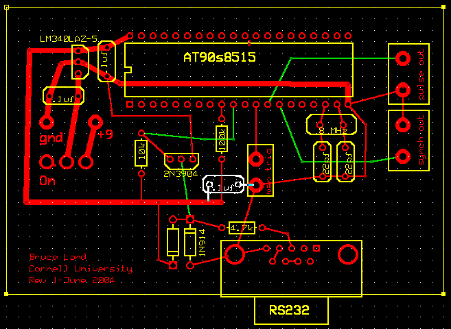
Appendix C. 8515 Circuit board
A circuit board was built using expressPCB software. The board can be viewed, modified, or ordered using software from expresspcb.com. This version assumes that only the timing output will be used, and not the amplitude control. Note that one capacitor (shown in white) was added after the circuit board was produced.

The modified user interface for this board is shown below. It has no amplitude control.