Oscilloscope and Physiological Stimulator
using a microcontroller and a TV
Introduction
This is an attempt to make a complete student electrophysiological instrument
based on a cheap microcontroller. The porject is based on an earlier TVscope.
The Vout (to the right) is driven from an opamp with input taken from an 7-bit
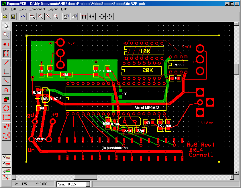
R2R ladder conencted to PORTC on the MCU. The ExpressPCB
(do a save as... on the following link and use ExpressPCB software) design
file.
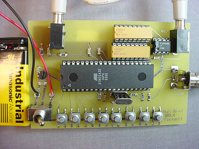
Parts list (Digikey part numbers):
- MEGA32-16PC Atmel microcontroller
- LM358 opamp
- LM340LAZ-5.0 regulator
- 901K snap-fit phone jack, 90-degree
- CP-3502N mono 3.5 mm audio connector socket
- 401-1103-1 rubber surface-mount push puttons
- CTX077 16 MHz crystal
- All resistors and capacitors are 1206 surface-mount packages
TVnuS details
Scope features:
- Displays one voltage channel.
- Full scale voltage range of 5, 2.5, 1.25 and 0.75 volts.
- Full scale time range of 8, 16, 33, 65, 130, 261, 521, 1042 mSec.
- Samples at 15.75 kHz maximum (NTSC video line rate).
- Cursor measurement of time and voltage on the trace.
- Trigger on level, with settable value, or freerun, or on stimulator pulse
start.
- RUN/STOP modes with manual arming in stop mode.
Stimulator features
- Produces a pulse train
- Amplitude settable 0-5 volts
- Duration settable 0.1-1000 mSec.
- Pulse repeat time settable 0.1-1000 mSec.
- Single pulse, double pulse, and repeat modes, with manual trigger in single/double
pulse mode. In double pulse mode, the pulse repeat time becomes the interpulse
interval.
The CodeVision C program is loaded on the Atmel Mega32. Please write me if
you want the source code. There are actually two versions of the code currently.
The first does only single pulses, the second does double pulses also. When
compiling, set the options to optimize for speed and to include floats in print
statements, and set the data stack size to 100 bytes. Set the clock fuze bits
to all-unchecked. You may need to uncheck the signature-check box.
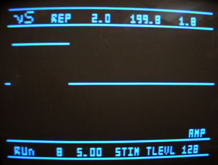
The above image shows a stimulator pulse. At the bottom of the display there
is a RUN/STP/ARM indicator, cursor readout of time and voltage
on the trace, a LEVL/STIM/FREE trigger indicator, and the trigger
level. At the top of the display is REPEAT/ONE/TWO/OFF pulse mode
indicator, the pulse duration, interpulse spacing, and the pulse amplitude.
Buttons:
- Button 0 toggles the stimulator ONE/REP/TWO/OFF mode.
- Button 1 triggers a single/double pulse in ONE/TWO mode.
- Button 2 toggle the scope RUN/STOP mode.
- Button 3 arms a capture in STOP mode. The capture actually occurs when the
trigger condition is met.
- Buttons 4 and 5 cycle through the settable parameters: HORZ, VERT, CURS,
TMOD, TLVL, AMP, DUR, SPAC. Respectively, these are horizontal time scale,
vertical voltage scale, cursor position, trigger mode, trigger level, pulse
amplitude, pulse duration, and pulse spacing.
- Button 6 decrements the parameter currently chosen by buttons 4-5.
- Button 7 increments the parameter currently chosen by buttons 4-5.
Internally, the program is divided into two parts:
- The timer1 compare-match ISR runs at video line rate. The ISR:
- generates the horizontal and vertical synch pulses
- blasts bits from RAM to the video output
- checks for a trigger condition, and acquires a voltage sample, if the
time is right.
- generates a pluse output sample.
- An external trigger pulse is latched by the INT0 interrrupt flag, but
there is no associated ISR, rather the timer1 ISR poles and clears the
flag.
- The main program:
- Sets up the environment, draws some strings, and drops into the usual
endless loop
- the loop sleeps until the whole video screen is drawn by the ISR, then
during the vertical sync time:
- draws a new trace, if it ready
- runs the button debounce state machine
- performs the button actions (move cursor, draw strings, etc) and
sets flags for the ISR
Copyright 2003 -
Cornell University - Bruce Land