Introduction
The goal of this project was to build a small, cheap, light-weight preamplifier for student use in electrophysiology labs. Specifically:
The Circuit
There is a passive lowpass filter at the input of the INA121 differential amplifier. The circuit was copied from the TI datasheet. The output of the INA121 is feed through a passive higpass filter, then to a gain stage of 1/2 of a LM358 dual opamp. The other half of the opamp package is used to split the 9 volt supply into +/-4.5 volts.
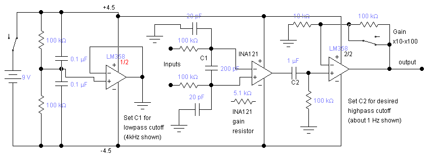
 The input stage is the most critical for common-mode rejection and noise. We
used a Burr-Brown INA121 differential
amplifier, set to a gain of 10 using a Rg1=5.1k. The input stage is DC coupled.
With a 4.5-volt supply, a differential DC offset of up to about 0.5 volt is
tolerable. Offsets of a few hundred millivolts are typical, assuming similar
metals for the differential electrodes. The common-mode rejection of the circuit
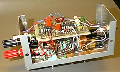
is as good as the Burr-Brown head-stage. The printed circuit board is shown
to the left. You need to download ExpressPCB
software to view the design file.
The input stage is the most critical for common-mode rejection and noise. We
used a Burr-Brown INA121 differential
amplifier, set to a gain of 10 using a Rg1=5.1k. The input stage is DC coupled.
With a 4.5-volt supply, a differential DC offset of up to about 0.5 volt is
tolerable. Offsets of a few hundred millivolts are typical, assuming similar
metals for the differential electrodes. The common-mode rejection of the circuit
is as good as the Burr-Brown head-stage. The printed circuit board is shown
to the left. You need to download ExpressPCB
software to view the design file.
Choosing Rg2=200kohm, Rg1=1kohm, Chi=10nf yields an amplifier with a low frequecy
cutoff around 150 Hz, a high frequency cutoff around 3.5 kHz and a settable
gain of 50 or 1000. Setting Rg1=5.1kohm and Rg2=100kohm makes the gains 10 and
100. Setting Chi=1microfarad (C2 on the schematic) makes the low frequency cutoff
about 1.5 Hz. Changing the 200pf capacitor in the input (C1 on the schematic)
to 100pf raises the high frequency cutoff to about 7 kHz. Three versions have
been built:
Parts list (part numbers are Digikey.com):
Battery clips (PCB mount) 594K and 593K
Switch SPDT surface mount AYZ0102AGRL 401-1001-1-ND
mono 3.5 mm audio connector socket CP-3502N
All resistors and capacitors are 1206 surface-mount packages
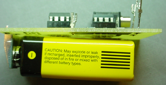
The following sideview shows how the battery is mounted. There is a piece of tape on the battery to protect it from the terminals of the two ICs.