Lab exercise 4
Pacemaker model.
Introduction.
You will use a pulse generator to build a pacemaker to drive a damaged version of the heart model you have built.
Procedure:
Read 555 timer datasheet.
Assignment:
Note that in this and every lab assignment the verb build means to construct a circuit on the protoype board with actual parts.
The verb simulate means use LTspice to mathematically simulate the circuit.
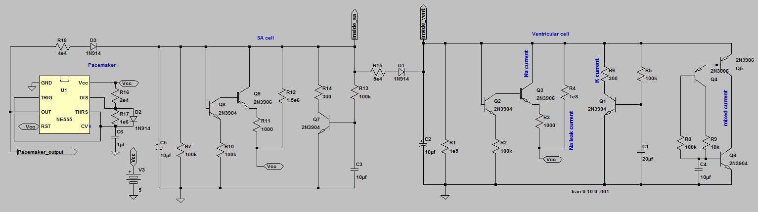
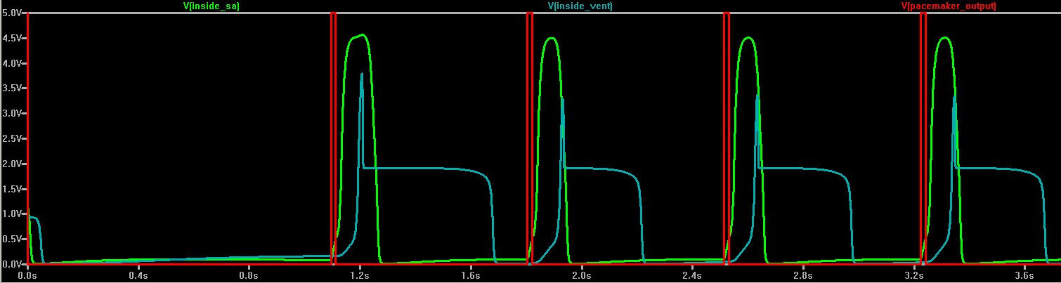
- Download simulate the following pacemaker circuit. Disable spontaneous heart beat by setting both Na leak resistors (sa and ventricle) to 1e8 ohms. In real life, this would be equivalent to a heart attack. Vary pacemaker rate, pulse length, and coupling resistor. Demonstrate phase lock between the pacemaker, SA node and ventricle models for some combinations of parameters.
- Build the pacemaker circuit using a 555 timer. Test to make sure it works and record the pulse length.
- Connect your pacemaker to your SA-ventricle circuit. You may need to play with the pulse width and or coupling resistor to get phase-locking. Record all the waveforms necessary to document that the system works.
This exercise completes the design of heart/pacemaker simulation.
Lab report:
- Introduction: Give a short explanation of what was done over the first 4 labs.
- Design and Testing Methods: Explain the approach you used for both software and hardware aspects of the assignment.
- The schematics of the circuits that you simulated or built.
- Calculations of RC time constants, currents, etc
- Results:
- Photographs of the circuits you built.
- Scope traces showing the the results of each circuit that you built.
- For the SA node alone, how did pulse rate depend on the Na leak resistor? Plot it.
- For the ventricular cell alone, how did pulse rate depend on the Na leak resistor? Plot it.
- For your SA node connnected to the ventricle circuit (built, not simulated) what were the ranges of coupling resistor and relative rates (varied with Na leak resistors) which resulted in 1:1 phase-lock or 2:1 phase-lock? Under what conditions (if any) did you see irregular rates.
- For the pacemaker circuit coupled to the SA node, which is coupled to the ventricular cell:
- With both the SA node and the ventricular cell rates disabled by setting the leak resistors to high values in the simulator, what were the ranges of coupling resistor which resulted in 1:1 phase-lock or 2:1 phase-lock?
- What were the ranges of coupling resistor and relative SA and ventricular rates (varied with Na leak resistors) which resulted in 1:1 phase-lock or 2:1 phase-lock? Under what conditions (if any) did you see irregular rates.
- Conclusions:
- Compare the model cells to real heart cells.
- Real hearts have a LOT more than two cells. How would many cells change the modeling?
- Designing a pacemaker requires minimizing current so that batteries last a long time. How might you do this?
- If you google up "SA block" you will find lots of plots of heart rates in which the SA node is partly decoupled from the ventricle. Do any of these plots look like what you see with the model cells?
- Answers to any other specific questions given in the lab writeups.
September 8, 2011
Copyright Cornell university