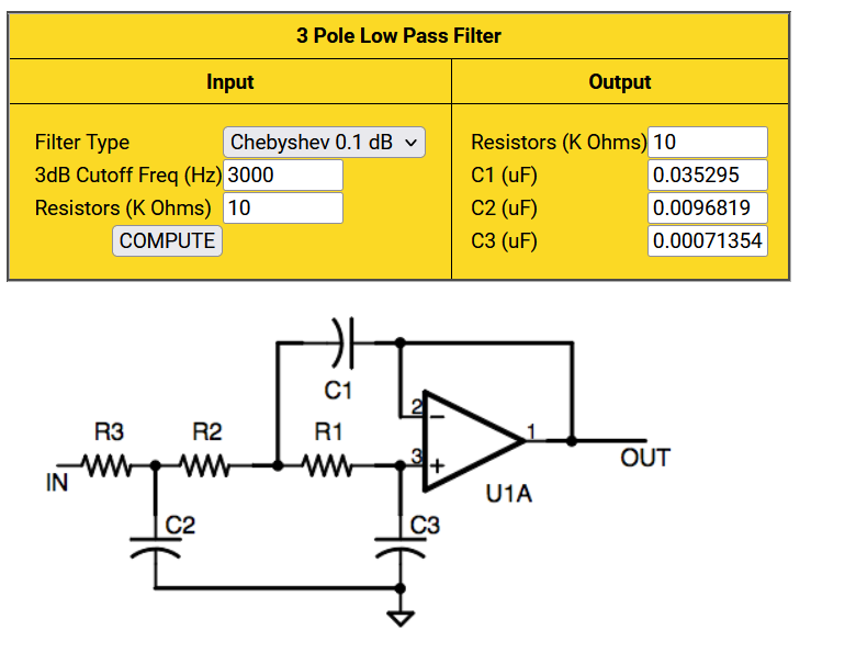
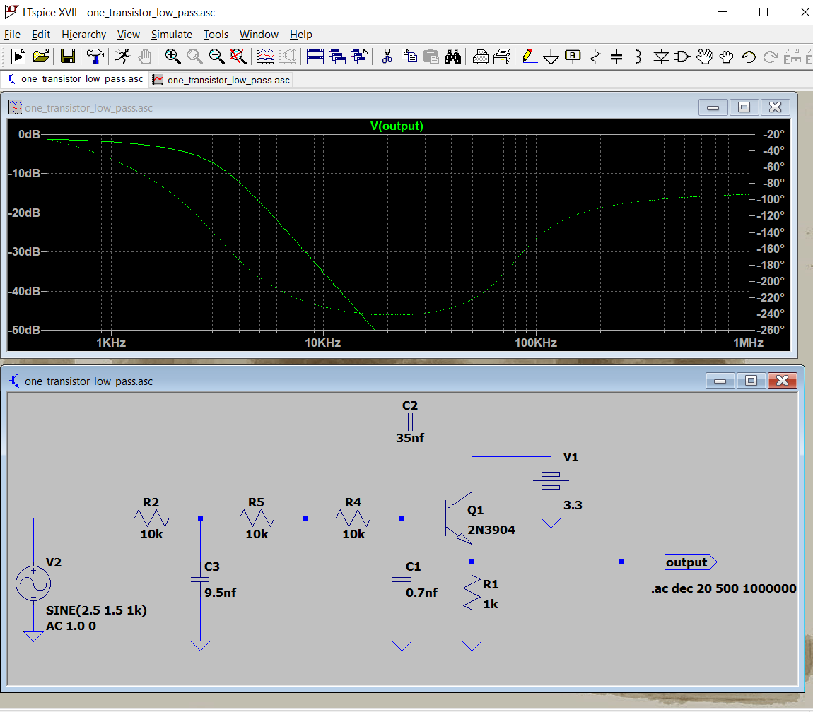
All sample data systems need bandwidth limitiation on their input to avoid aliasing. A simple RC filter will sometimes work, but a higher order active filter is often necessary. It is possible to build a 3rd order Butterworth or Chebychev filter with one opamp, or even one transistor! There are many possible designs but a 3-pole active filter design utility by Stellar Coding is easy to use to build a opamp version. Note that in the circuit diagram below (from the web page) the opamp is configured as a unity gain follower. That means that we could use a single BJT as an emitter follower, if the input and output offsets worked out right. A commercial microphone module, such as Electret Microphone Amplifier have an ouput offset of Vdd/2. If powered by 5 volts then the output offset in 2.5 volts, with an active range of +/-1 volt from 2.5 volts. Using this to feed the BJT circuit (ltspice .asc) below subtracts one silicon diode drop, 0.7 volts, from the 2.5 to make 1.8 volt offset, just about perfect for the PICO ADC. Either filter rolloff is 60 db/decade. The BJT filter is low power, but will not be as ideal as the opamp version. If you power the microphone from 3.3 volts, then just use the opamp circuit.
