ECE 4760 Final Project: Persistance of Vision Clock
Christopher Zheng (cfz4@cornell.edu)
Sean Hubber (sjh234@cornell.edu)
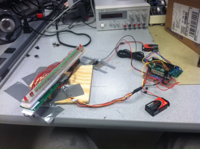
The goal of our project was to create a persistence-of-vision (POV) analog clock using an LED display. The clock has a visual alarm system which lights up the entire display for two seconds if it reaches an alarm time. The current time and alarm times are preset into the clock before it begins to spin. Once the times are set, the clock spins up to a very stable speed, where small interferences will not disrupt the rotation of the clock. Once at max speed, the clock pulses LEDs to create a persistent display of the current time.
High Level Design
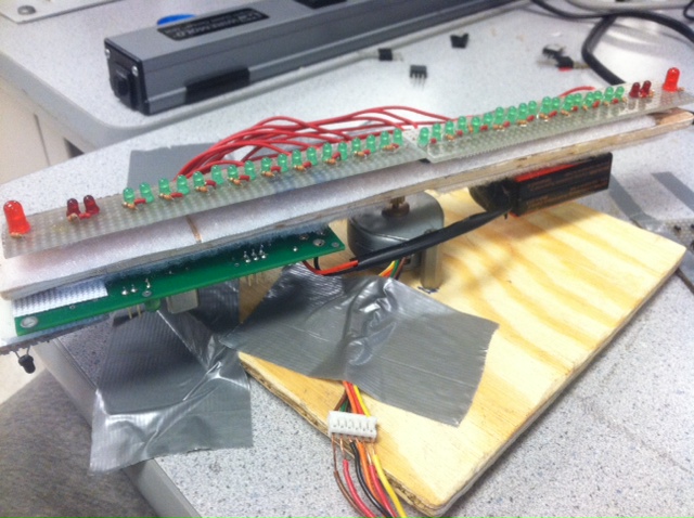
The basic premise of the POV display is that you pulse the LEDs such that on each revolution they are flashing in the exact same location. If this is happening fast enough, the human eye cannot detect the down time between flashes, and will see it as the LEDs being constantly on in one location. In order to achieve this, we determined that the LEDs needed to blink in the same location at least ten times per second to appear persistent. In order to achieve this speed, we were able to get the stepper motor to step every 4 ms. Each step of the motor is 7.5 degrees, so it requires 48 steps to complete one full rotation. This means that it takes 4*48 = 192 ms per revolution. This translates to 5.21 revolutions per second. This was only half the speed we needed, so we put a row of LEDs on either end of the spinning blade, effectively doubling the frequency of the LED flashing, since we could flash twice per revolution. This increased the frequency to 10.42 flashes per second, which was sufficient to achieve persistence of vision.
In order to ensure that the LEDs are flashing in the exact same location each revolution, we connected a photodiode to the underside of the spinning blade. This photodiode detects a line of IR LEDs that are fixed to the table. Each revolution, the clock is set relative to the fixed LEDs, with 12 o’clock located at the LEDs. This prevents any phasing in the display caused by compounding of errors, since any error is corrected each revolution. The photodiode/LED system also recalculates the period every revolution. This is used to adjust for any slight variations in the motor speed.
The basis for the alarm clock is simple. If the current time equals the alarm time, the full display is lit for two seconds. After these two seconds, the clock returns to ticking normally (it does not miss two seconds while the alarm is on).
Hardware Design
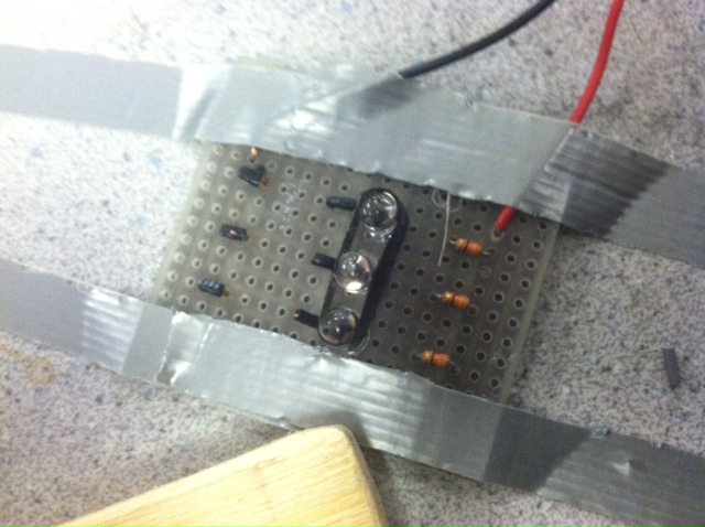
LED Display
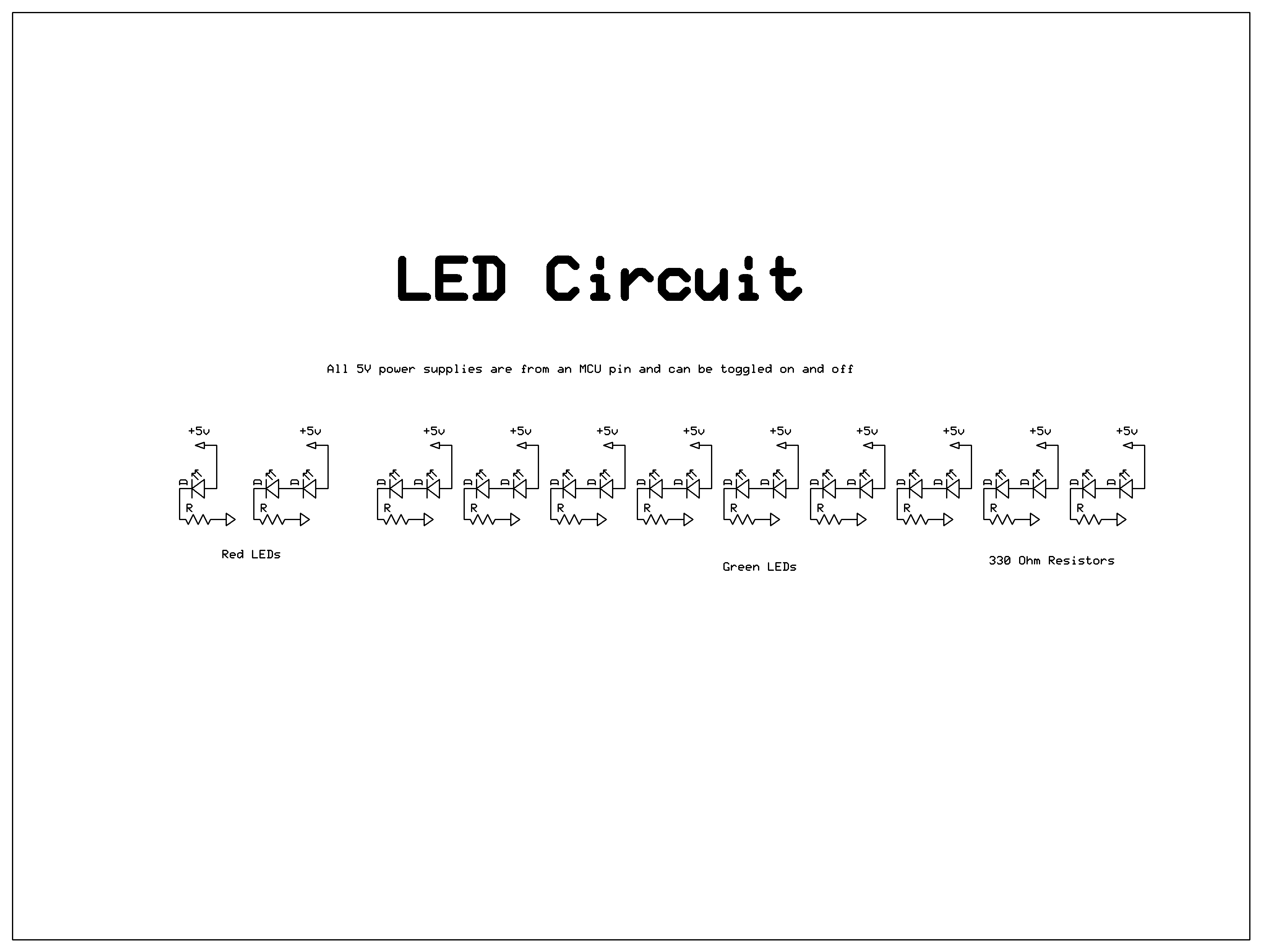
The design of the LED display was made more difficult by the fact that we only had 5V of power out of the MCU to power the LEDs. Because of this, we could only put two LEDs and a resistor (to prevent the LEDs from burning out) in series while still achieving satisfactory brightness. This meant that we needed nine pairs of green LEDs, a pair of red LEDs, and one large red LED on each side of the blade. Each pair of LEDs (and the large red LED individually) was powered by its own pin in the MCU and was turned on by simply setting that port high. While this required many more MCU pins and more switching in the software, it also gave us more control of the display by allowing us to control smaller elements. This control could be used to create more intricate displays for alarms, or other non-clock related displays.

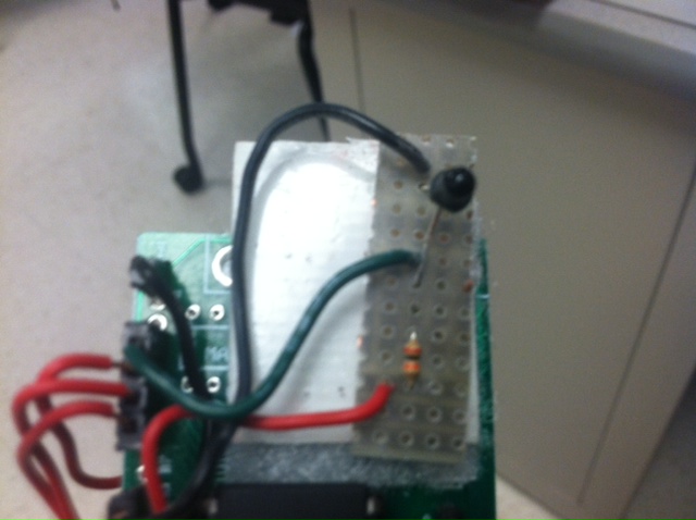
Photodiode/IR LED system
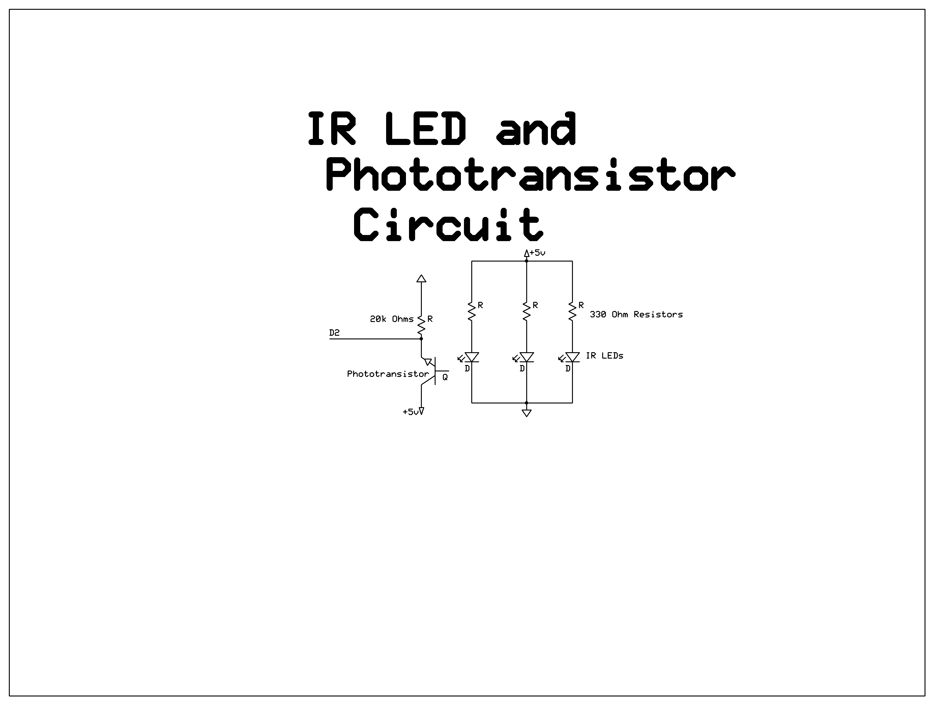
The photodiode/IR LED system is very straightforward. Normally, the voltage at D2 is high, since the unlit photodiode acts as an open circuit. As the photodiode passes above the IR LEDs, the photodiode become a closed circuit, and pulls the voltage at D2 to ground. Once the photodiode is passed the IR LEDs, the voltage at D2 goes back to high. This rising edge is then used by the MCU to trigger the interrupt that sets the 12 o’clock location and the tick distances.
The IR LEDs are continuously powered, and are each in series with a resistor to prevent them from burning out.
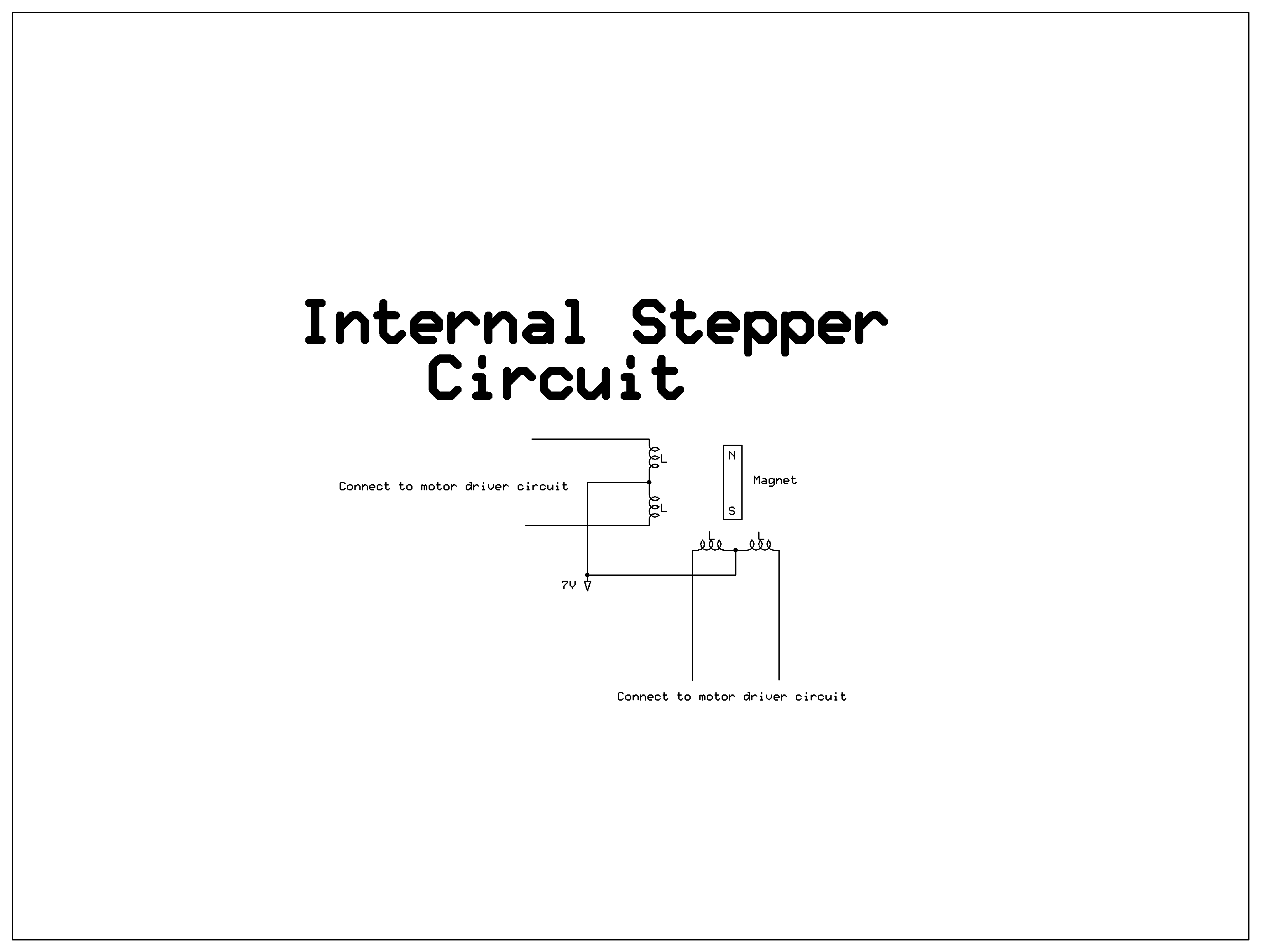
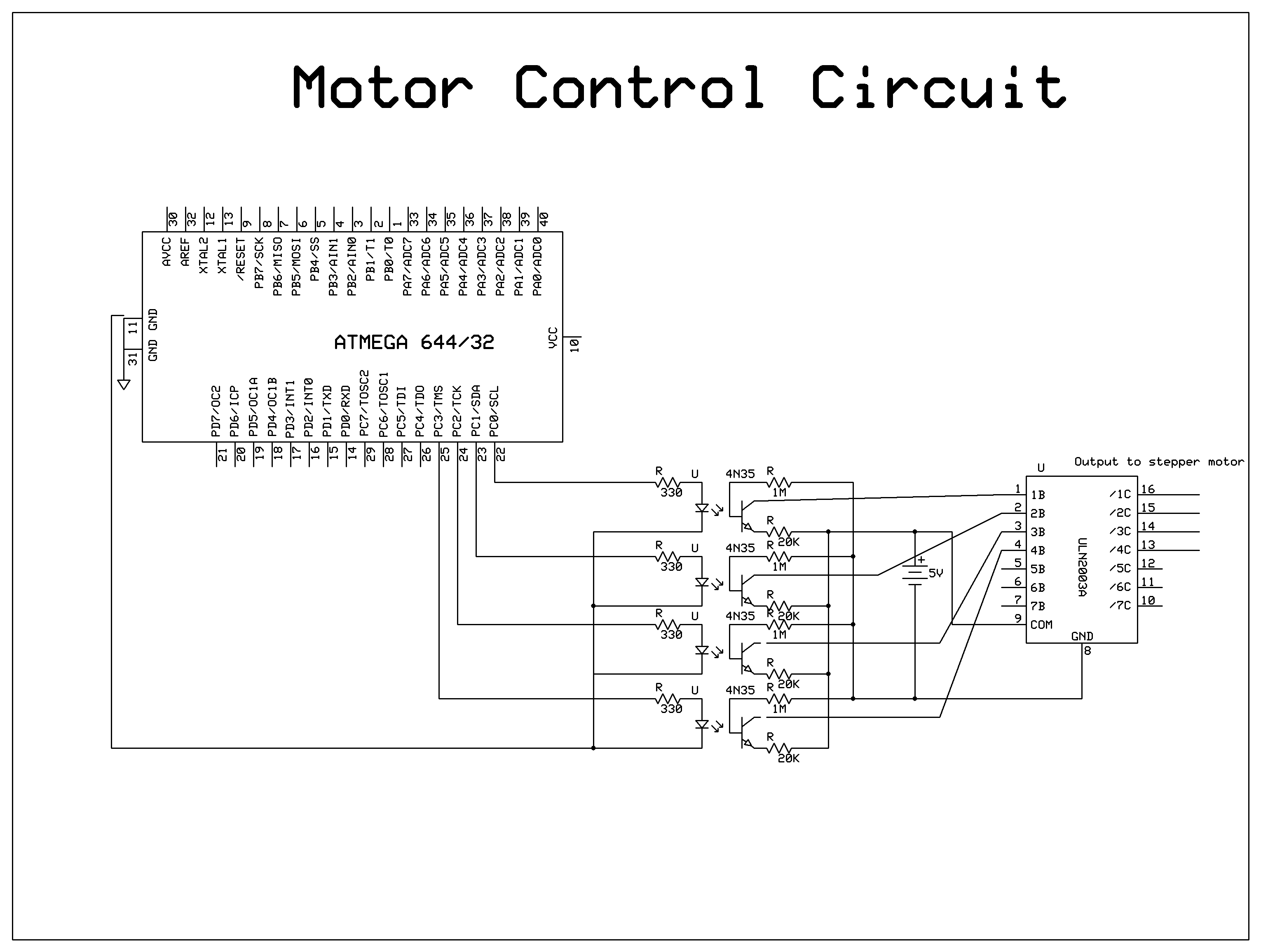
Stepper Motor Driver
The inductors are set so that Vcc is constantly applied to the center of each inductor, and you can control the flow of current by grounding either side. To control this grounding, the end of each inductor is connected to ground across a transistor. The four transistors necessary for this are contained within the ULN2003 chip. The voltage on the gate of these transistors is connected to photodiodes, which are controlled by LEDs connected to four separate pins on the MCU. Each pair of photodiode and LED is contained within a single 4N35 chip. When a pin is set high, it turns on the LED which in turn allows current to flow through the photodiode, this changes the voltage on the gate of the transistor and allows current to flow between the drain and source, grounding the end of the inductor. This process is controlled by software so that the inductors are set in such a way that the magnetic fields pull the magnet in a circle.
The inductors are set so that Vcc is constantly applied to the center of each inductor, and you can control the flow of current by grounding either side. To control this grounding, the end of each inductor is connected to ground across a transistor. The voltage on the gate of these transistors is connected to photodiodes, which is controlled by LEDs connected to four separate pins on the MCU. When a pin is set high, it turns on the LED which in turn allows current to flow through the photodiode, this changes the voltage on the gate of the transistor and allows current to flow between the drain and source, grounding the end of the inductor. This process is controlled by software so that the inductors are set in such a way that the magnetic fields pull the magnet in a circle.
Software Design
Motor Implementation
In order to get the motor to rotate clockwise, we must take into account two factors: (1) cycling through the four inductors and (2) ramping the motor. Pins C0, C1, C2, and C3 corresponds to each of the four inductors. In order to get the motor to spin, we cycled from C3 -> C2 -> C1 ->C0 by turning the corresponding pins high and then back low. As a result, each pin will be producing a square wave at a certain frequency. Furthermore, there is a 50% overlap of the square waves with the next pin. This way, we can produce maximum torque of the motor and allow additional weight to be placed on the motor. The cycling between pins will happen faster and faster as we ramp the motor.
Because of the fact that we cannot turn on the motor at maximum rotational speed, we must start it slow and decrease the time it takes to cycle through the pins. To achieve this, we have a counter called “multiplier” that sets the duration between going to the next pin output. The multiplier starts off at 150 and will decrement by 1 every 5 cycles until it becomes 90. From that point, multiplier will decrement by 1 every 10 cycles until it reaches an absolute minimum at 40. We found that a multiplier of 40 will produce a maximum rotational speed with our stepper motor. A lower minimum multiplier value will cause the motor to slip since the weight of the load is too much. With this absolute minimum multiplier in mind, we can determine the maximum rotation per second of the motor.
Tick Marks Implementation
With the infrared detector and emitter, we are able to detect when the blade will cross a fixed location at every rotation. The detector will receive a 0-5V square wave with each rotation. This square wave will trigger the ISR (INT0_vect) on every rising edge. Within this interrupt, it calculates the period elapsed from the previous interrupt. This will give us the time it takes for the blade to make one full rotation. From this period, we divide it by 12 and save it off as “incrementTick”. We have a second interrupt, ISR (TIMER0_COMPA_vect), that triggers every 100us. Within this interrupt and with “incrementTick” variable, we set a counter that counts up to that duration, turns on the tick mark LEDs for 300us and resets the counter. This will produce 12 evenly spaced tick marks in a circle. The reason we chose a 100us interval is because 1ms will not be accurate enough in timing and 10us will be too fast for the code to execute before the next interrupt is triggered.
Second Hand Implementation
With the concept of generating the spacing of the tick marks in mind, it became very simple to generate the second hand. In the ISR (INT0_vect) that triggers on every rising edge of the infrared detection, we also divide the period by 60 and called this “increment60”. Just like the tick marks calculations, we can determine every second hand location by multiplying “increment60” by the current second. This will display the second hand at the correct location in ISR (TIMER0_COMPA_vect) once the calculated duration has elapsed. We turn on the second hand for only 100us for it to be a finer line. We update the current second value by one with a global counter that counts the number of times the 100us interrupt has been triggered. Ideally, the global counter would have to count to 10,000 before a second has elapsed. After calibration, for some reason, the global counter needs to only count to 961. We can only assume that interrupts are potentially not completing in time for the next interrupt to be triggered.
One issue we originally had was that the second hand would not complete a full rotation. This is due to the fact that our counter is an integer type while dividing the period by 60 (“increment60”) will almost never be perfectly even. As a result, there will be a remainder of time left which will cause the second hand to jump from the 57 second mark to the 60 second mark as the current second resets back to 0. This is clearly undesirable. To solve this issue, the ISR (INT0_vect) calculates the remainder of time left and how often every X second would need to increase by an extra 1ms. To make this clearer, I will provide a simple and realistic example: if the current period of rotation takes 2000 counts, increment60 = 33.33. Since the counter that determines if the position of the current second has occurred is an integer, it would only count to 33 before turning on the second hand LEDs. As a result, 2000 - (33*60) = 2000 - 1980 = 20, 20 counts will be missing in a rotation. Therefore, 60/20 counts = every 3rd second would need to increment by 1 count more in order to make up for the remainder of time lost.
Minute and Hour Hand Implementation
Lastly, the minute hand and hour hand have the same logic as the second hand implementation. Both the minute hand and hour hand will increment by “increment60” in the ISR (TIMER0_COMPA_vect). The minute hand will increment once the current second has reached 60. The hour hand will increment once the current minute has reached a multiple of 12. This is done so that the hour hand will move smoothly and more realistically from one hour to another rather than a sudden jump between hours.
Current Time Calculations
Our code will have the current time hard-coded into the variables: currentHour, currentMinute, and currentSecond. As a result, once the clock display is turned on, the correct hard-coded time will be displayed since we are multiplying those variables by “increment60” in order to get the right position of the rotation.
Alarm Time Calculations
Our code will also have the alarm time hard-coded into the variables: alarmHour, alarmMinute, and alarmSecond. Because we are keeping track of the current time it was very simple to detect when the alarm is supposed to go off by having an if-statement to check if the alarm variables are equal to the current variables. We set the alarm to go off for 3 seconds by allowing the alarmSecond to be within 3 seconds of the current second. To display the alarm, we leave the hour hands on for the 1st second, minute hand for the 2nd second, and the second hands for the 3rd second. This produces an interesting spiral outwards.
Results
When we used a stopwatch to time the second hand every 5 seconds, the result was almost exact; and we think that any error was caused by human inaccuracies in starting and stopping the stopwatch. By visually counting 60 seconds, we can see that the second hand makes a complete rotation without significant gaps We tested the alarm by setting the alarm to one minute after what we set the current time to. The alarm worked exactly as expected by lighting up right when the current time matched the alarm time and produced a spiral with the LEDs in a 3 second duration. Furthermore, when testing in the dark, the results of the display looks persistent enough to the human eye.
Conclusion
Our initial project goal was to implement an LCD and keypad connected to the POV display in order to have the user to be able to modify the time and alarm time dynamically as the motor is spinning. However, we realized that this would require a wireless communication between the MCU on the motor and the MCU connected to the keypad. After a week of testing the wireless transceivers, we ran into multiple issues that significantly delayed our project. Therefore, we downscaled our project and focused our attention towards creating a POV without the dynamic user input. With this new goal in mind, we are satisfied with our end result since the clock worked as intended in producing a convincing persistent display. If we had additional time, we would have continuing working on the wireless communication as well as making the entire system run on 9V batteries.
Appendix
Documentation
Motor Control
This code drives the motor such that the motor starts at a relatively low speed and slowly accelerates until it reaches the maximum set speed.
ISR (TIMER0_COMPA_vect) - Timer 0 will count every 100 us before calling the interrupt. Within the interrupt, we will increment timeCounter and call spinMotor(). timeCounter keeps track of the number of counts of 100us.
spinMotor() - This function will check if timeCounter has reached a certain value and turn on the appropriate pin to high, which will turn on one of the four inductors that will rotate the motor. There are five possible times: as indicated by timerCounterX * multiplier, where X = {0,1,2,3,4}. The multiplier will regulate the duration of time between each if-statement. Initially, multiplier starts at 150 so the time it takes to get from each if-statement block is 150*100us = 15ms. After we turn on each of the four inductors in order, we will increment flag which keeps track of the number of cycles. After 5 cycles, we decrement multiplier; this is what creates the ramping as the time between switching on the inductors is shorter and thus the motor spins faster.
One important thing to note is that we turn on each inductor for twice the if-statement duration. So initially, the first inductor is turned on for 30ms from time 0. The second inductor is turned on 15ms from time 0 and turned off at 45 ms, and so on. This creates a 50% overlap of time between the current and next inductor in order to create maximum torque for the motor. Without this, we would not have been able to drive the motor with the given load.
Clock Display
This code controls the LEDs on the motor to flash at specific times and durations in order to generate a POV display of a clock.
ISR (INT0_vect) - This will interrupt once the phototransistor detects the infrared LED that is fixed in positioned. As a result, we will know the exact time it takes for the motor to complete one full rotation. In this interrupt, we can take the current duration that is calculated from Timer0 and divide it by 12 and 60 in order to divide the visual clock into equal segments. We divide by 12 in order to generate the 12 tick marks to denote the hour. We divide by 60 to know the location of the second and minute hand location.
Because of the fact that the period will not be in exact multiples of 60, there will be some remainder that occurs as discussed previously. Therefore, we have to calculate the remainder through “timeRemainder = currentPeriod - 60*((int)increment60);” and find out how often we should increase a second hand duration for every X number of seconds.
ISR (TIMER0_COMPA_vect) - This is the main bulk of the code. Here we take the times determined from ISR (INT0_vect) and turn on the LEDs for 300us (for tick marks) and 100us (for hands).
To turn on the tick marks, we simply keep a counter called “usCounter” which keeps track of the number of 100us that has occurred in every rotation. Once it reaches every multiple of the currentPeriod/60, we turn on the tickMarks for 300 us. This creates a nice and evenly spaced 12 tickmarks.
To create the second hand, we need to count the time it takes from the 12 o’clock position, to where our second hand is. Because we know how long a 60th of the period is, we can take the current second and multiply it with a 60th of a period. This will place our second hand at the correct location. This idea is extended to the minute hand and hour hand.
In order to get the second hand to move, we have a globalMS counter that will increment until it reaches 1 second in this interrupt. Ideally the threshold value is 10,000 counts of 100us to reach 1 second. However, it seems that our threshold is 961 after calibration. We are not completely sure as to why the threshold is much lower than the ideal value. We can only guess that this interrupt is not completing in time before the next interrupt and thus interrupts are skipped. Nevertheless, the clock keeps track of time accurately. Once a second has been counted, we can simply increment the current second and its new position will be updated automatically. We have to add additional time to each second hand location because of the remainder of time issues described in the previous section. Again, this idea is extended to the minute hand and hour hand.
Finally to display the alarm, we check to see if the current hour and minute are equal to the alarm hour and minute; and if the alarm second is within 3 seconds of the current second. If the seconds are exact, we leave on the hour hand. If the second is 1 greater than the alarm second, we leave on the minute hand. If the second is 2 greater than the alarm second, we leave on the second hand. This creates an outwards spiral for 3 seconds that indicates when the alarm has turned off.
Other functions - The rest of the functions are self explanatory. They control the tick marks, second, minute, and hour hands. An input parameter of 1 will turn on the corresponding LEDs and 0 will turn them off.
Cost Analysis
| Part Description |
Unit Cost |
Quantity |
Vendor |
Total Cost |
| Green LED |
$0.04 |
36 |
Lab Stock |
$1.44 |
| Red LED |
$0.04 |
6 |
Lab Stock |
$0.24 |
| IR LED |
$0.04 |
3 |
Lab Stock |
$0.12 |
| Phototransistor |
$0.00 |
1 |
Lab Stock |
$0.00 |
| Battery Connector |
$0.00 |
1 |
Lab Stock |
$0.00 |
| Velcro Strips |
$5.00 |
1 |
Walmart |
$5.00 |
| 9V Battery |
$1.42 |
1 |
Amazon |
$1.42 |
| Salvaged Atmega 1284P |
$0.00 |
1 |
Lab Stock |
$0.00 |
| Salvaged Atmega 644 |
$0.00 |
1 |
Lab Stock |
$0.00 |
| Stepper Motor |
$0.00 |
1 |
Lab Stock |
$0.00 |
| Wood Piece |
$0.00 |
1 |
Lab Stock |
$0.00 |
| Solder Board |
$2.50 |
1 |
Lab Stock |
$5.00 |
| Header Pins |
$0.05 |
82 |
Lab Stock |
$4.10 |
| 330 Ohm R |
$0.00 |
29 |
Lab Stock |
$0.00 |
| 20k Ohm R |
$0.00 |
5 |
Lab Stock |
$0.00 |
| 1M Ohm R |
$0.00 |
4 |
Lab Stock |
$0.00 |
| 4N35 Chip |
$0.50 |
4 |
Lab Stock |
$2.00 |
| ULN2003 Chip |
$0.50 |
1 |
Lab Stock |
$0.50 |
| Wire |
$0.00 |
15' |
Lab Stock |
$0.00 |
| Total |
|
|
|
$19.82 |
Task Breakdown
Sean Hubber created the hardware design for the motor control, the LEDs boards, and the infrared detector/emitter.
Christopher Zheng created the software for implementing the display and timing of the POV.
Both members contributed in software of driving the motor and developing the proof of concept of creating a persistent display with the LEDs.
Source Code
Motor Control Code
Clock Display Code
Intellectual Property and Other Legal Considerations
Only the initialization of the external interrupt ISR was directly used from Professor Bruce Land’s lab 4 manual (see reference). All other software was development by Christopher Zheng and Sean Hubber.
Ethical Considerations
To our knowledge, we have followed the IEEE Code of Ethics regarding our ECE 4760 project: Persistence of Vision Clock. Due to the quick flashing of the LEDs, this device may cause epilepsy. As for safety considerations, every part on the blade has been securely fastened using velcro, a provenly strong material for holding materials together.
References
ECE 4760 Course Website
ECE 4760 Lab 4 Reference
Mega 1284 Datasheet
Acknowledgements
We would like to thank Professor Bruce Land (brl4) for providing lab equipment for the majority of our project as well as providing extremely useful insight on debugging certain designs. Furthermore, we would like to thank our TA, Amrit Singh (as2799), along with the other TAs for helping us implement the logic of the display.