
 |
|
|---|---|
 |
Introduction
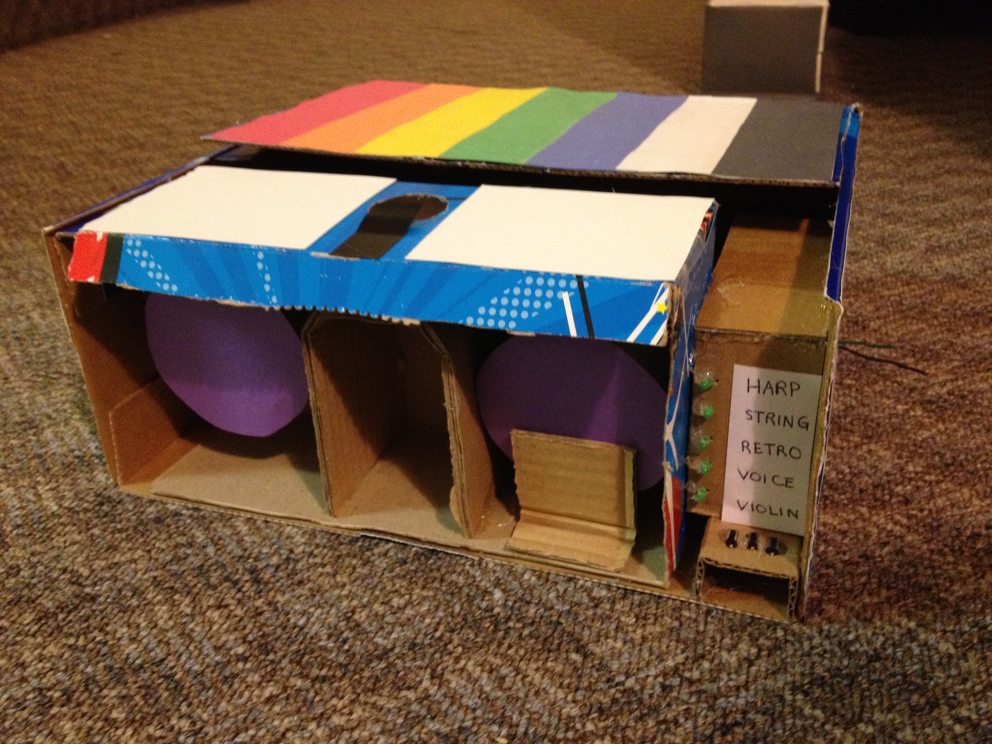
We created a device that determines the RGB content of a surface and then speaks the color or plays a musical tone at the sound frequency mapped to the color. The device can convert the color to sound directly or function as a cassette player that plays through a tape of colors. The user can select between several instrument sounds, which were implemented using different methods to achieve realistic effects. We both wanted to create a music-based project, and when we came upon the idea of color-to-sound conversion, it inspired us to create a product that can serve as an outlet for synesthetes, an aid for people who are visually impaired, or fun musical toy for everyone.
High Level Design
Rationale and Inspiration
Synesthesia, a neurological condition in which certain senses are merged, is a strange yet interesting phenomenon. After exploring its various forms, we were particularly fascinated by audio-visual synesthesia. In some cases of this condition, the person hears a noise or tone upon seeing a particular color. Since we already intended to create a music-based final project, the idea of recreating this synesthetic effect and converting color to sound caught our attention. Thus, we decided to build an interesting musical device based on color detection.
Background Math
The color detection unit is based on the RGB color model and works on the principle that a surface will reflect more of the color that matches its own color. The colors that we chose to detect for a full octave of musical tones are red, orange, yellow, green, aqua, blue, violet, white, and black - these colors have very distinct RGB content, which makes color detection less vulnerable to sources of inaccuracies.
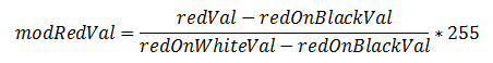
For our color detector, we shine red, green, and blue LEDs onto a surface one at a time and use a photoresistor to detect the amount of light reflected for each color. Even with ideal LEDs and photoresistor, the surface material can cause discrepancies in the RGB readings. Any time a new surface is used for color detection, calibration needs to be completed before color sensing can begin. During calibration, the black surface and white surface responses are recorded for R, G, and B. This gauges the natural reflectiveness of the surface. Since theoretically, black does not reflect any colors and white reflects all colors with maximum intensity, the black and white RGB values set the lower and upper bounds. By linearly interpolating any given R, G, or B reading to the black and white RGB values, the unwanted effects of different surface textures and materials are minimized. As an example, the following equation performs the linear interpolation on the red ADC value and sets the value to range between 0 and 255 (the amount of resolution that the ADC originally provides):
Next, each modified RGB value is scaled to the most prominent color's value such that each color ranges between 0 and 100, which is an intuitive range to work with. By normalizing each color to the brightest color, the dimness/brightness of the colored surface will not affect the color sensed as long as the R, G, and B content relative to each other is representative of the hue of the surface.
As mentioned earlier, the colors that we chose to detect for the musical tones have distinct RGB content and are least prone to error. Through trial and error, we determined the color detection threshold levels that are most robust to non-linearities in RGB responses, changes in surface material, and ambient lighting.
Direct Digital Synthesis (DDS)
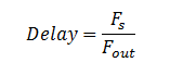
The DDS method was used to generate some of the device's musical sounds, including harp, violin, and "retro" (video game tone). In this method, each instrument (including the retro sound) corresponds to a table with 256 values initialized for one period of the sound wave. The MCU outputs the values in the table to produce the PWM signal to be eventually sent to the speakers. Since the DDS accumulator is 32 bits running at 62.5 kHz, the increment value for going through the table follows the equation,
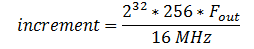
where Fout is the desired sound frequency. The larger the increment value, the larger the steps through the table and the smaller the period of the waveform - this all translates to a higher frequency output. The resulting PWM signal running at 62.5 kHz with varying duty cycles is then low-passed - the area under the PWM signal is integrated - to produce a "smooth" signal usable by the speakers.
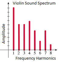
Any given instrumental tone is composed of a distinct set of harmonics with certain amplitudes corresponding to the harmonics. For the harp, when a string is plucked from the middle, the sound produced is extremely close to that of a sine wave. Thus the table that we initialize to generate the harp sound is one period of a sine wave. Often, older video games use square waves for their sound effects, so we included a retro video game tone, which uses a table of one 50% duty cycle square wave. The violin (bow) sound is composed of several harmonics with amplitudes that correspond to its sound spectrum.
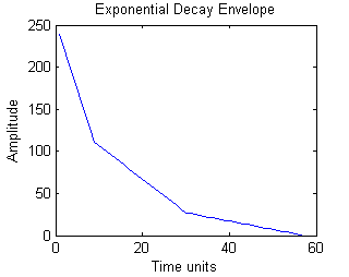
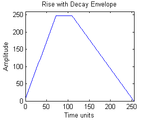
Since sounds coming from most physical instruments experience decay due to the mechanical components dissipating energy, we apply rise and decay envelopes to the sounds produced. The tables are initialized before sound generation begins, and they are multiplied to the output signals during sound generation. Below are the signal envelopes for Harp and Retro (left) and Violin (right):
Karplus-Strong Algorithm
The plucked string sound uses the Karplus-Strong Algorithm. Physically, right after a string is plucked, the string vibrates energetically and the sound wave produced contains many harmonics. Over time, the energy in the string dissipates and the sound wave has fewer and fewer harmonics, until the string stops vibrating. The Karplus-Strong Algorithm models this process by starting off with an array of random values representing the sound from the initial strike of the string.
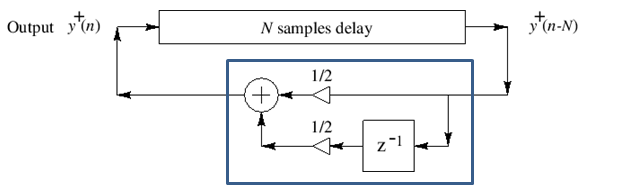
Each value in the array is averaged with the previous value, which decreases the amount of change between samples and serves the same function as low-passing the waveform. Thus, the high frequencies from the original noise array are gradually removed from the signal, "smoothing away" the higher harmonics. The averaged values are then fed back into the filter, and this process is repeated until all of the string's energy is dissipated, or in other words, the signal is low-pass filtered so many times that the signal dies out. The pitch of the sound produced depends on the length of the array; since the same set of values is being low-pass filtered, a periodic waveform can be achieved. A longer delay corresponds to a longer period and a smaller sound frequency. The appropriate delay can be approximated by the equation:
Logical Structure
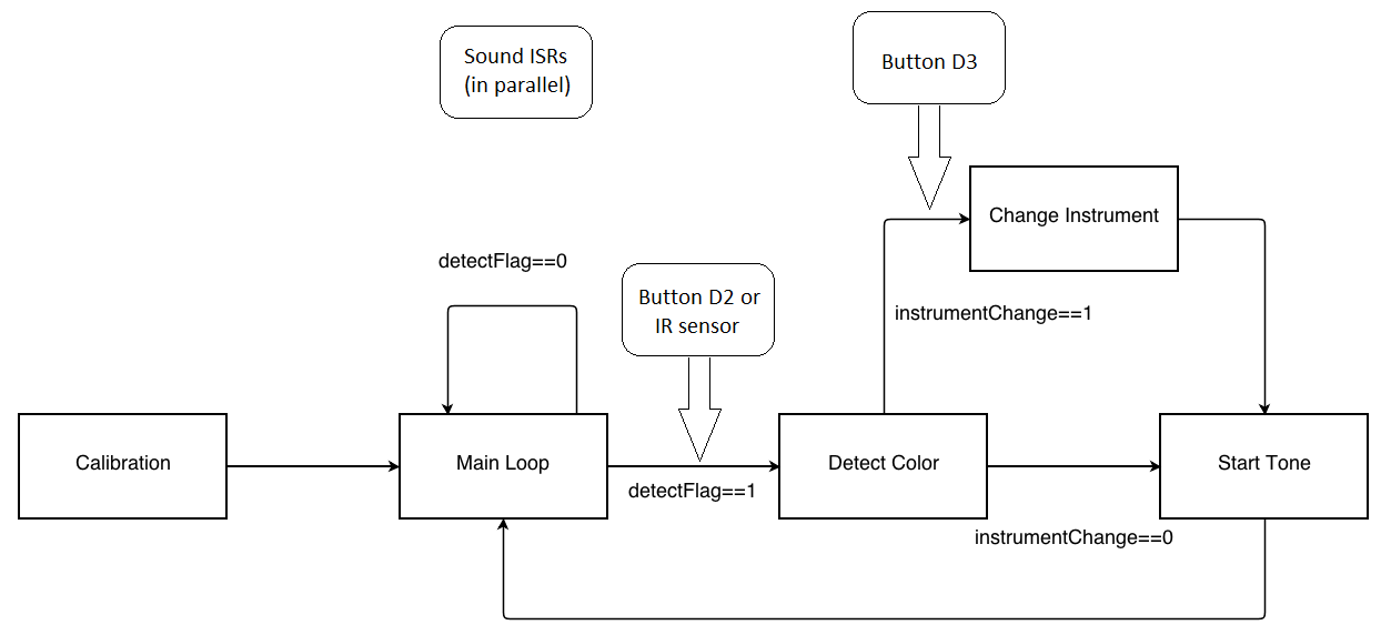
The initial step consists of calibrating the color sensor. During this stage, a button push is required to initiate both the black and white calibration separately. The reason for including a button is so that the user has time to place the sensor on the black or white object before sensing begins. The following actions therefore occur: place sensor on black, press button, wait for sensing of black, place sensor on white, press button, and then wait for calibration end signaled by a tone.
After calibration, we wait in a while loop until either the detection button is pressed or the IR sensor is triggered. When either of these interrupts occurs, we enter the color detection state. To detect a color, each of the RGB LEDs are toggled and the amount of reflected light is measured and processed. Once the color has been determined, we check to see whether a new instrument has been selected. If one has been selected, then the current instrument is set to the new one. Whether or not a new instrument was chosen, we initialize a new tone by resetting the corresponding parameters. Finally, we return to the while loop to wait for another interrupt to trigger detection of color again.
While the rest of the code is executing, the ISR that generates the sound corresponding to the currently selected instrument is active. After a tone is finished, another sound is only produced when the detection button is pressed or IR sensor is triggered. The start_new_tone method will reinitialize values so a tone can be played again.
Note that there is a separate button from the color detection button for the instrument selection. Each time that this selection button is pressed, nextInstrument is set to the next instrument in line and the corresponding green LED in the line lights up. The order is as follows: harp, string, retro, voice, and violin. Only when a new tone is started is the actual instrument being played changed.
Hardware/Software Tradeoffs
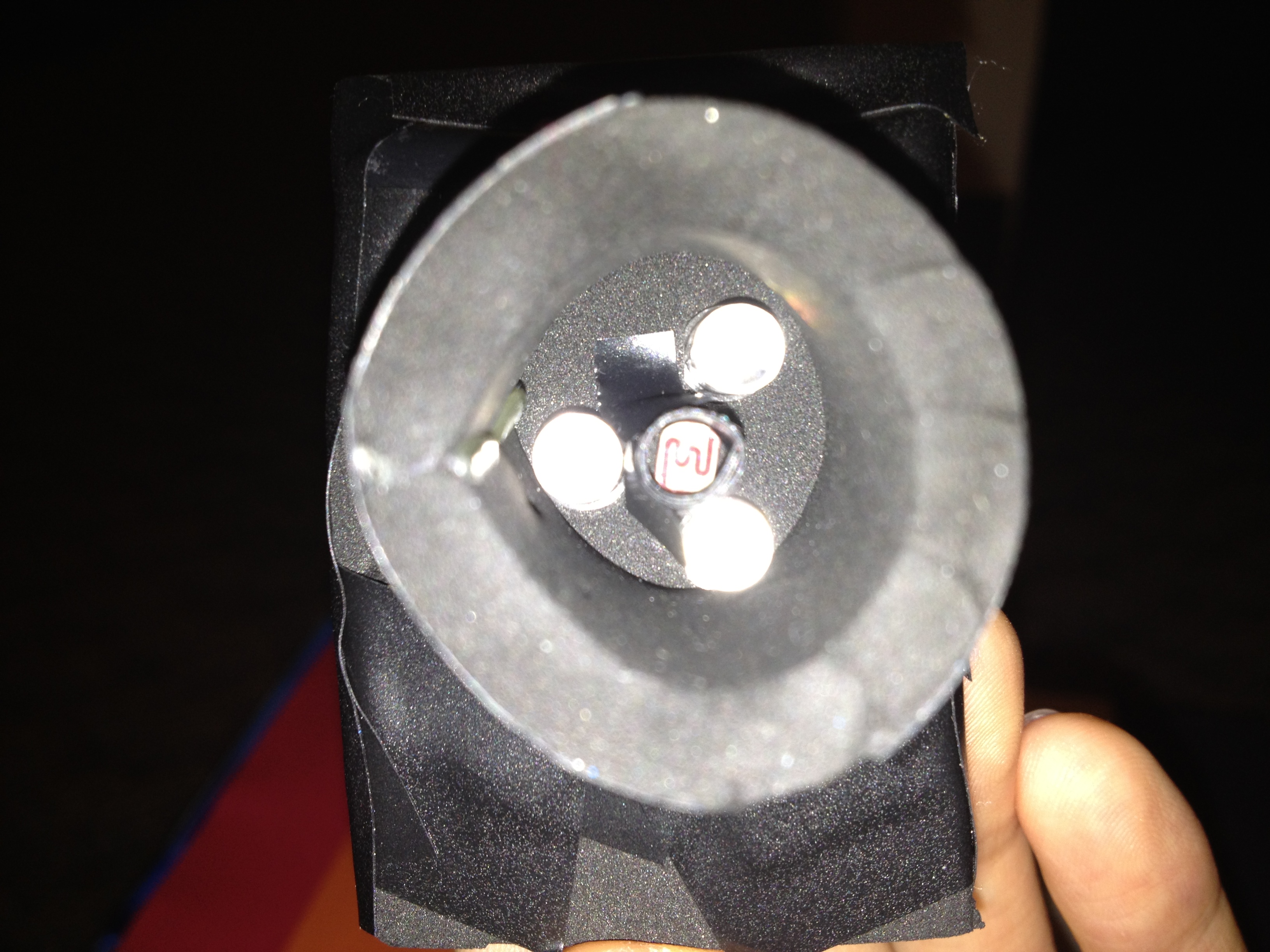
We considered several options for the light detector, including phototransistors, photodiodes, and photoresistors. Phototransistors and photodiodes respond to light much faster than photoresistors (microseconds versus milliseconds), but photoresistors have spectral curves that closely match that of the human eye. For our application, a fast response time is desirable, but because we will be playing a note after each color detection, at least a few hundred milliseconds is free for color detection, which is more than enough time for the photoresistor to respond. The human-like spectral response of the photodetector is important to our color detection unit, so in the end, we picked a CdS photoresistor. We decided to use three LEDs, each a different color, rather than one LED that can output all three colors. Although one RGB LED requires less surface area to detect color, three LEDs gave us more control over each LED separately (for example, brightness levels can be adjusted separately).
For sound generation, we had to make a decision between having separate timers for the voice and the plucked string sound versus including all instruments in one ISR for simplicity of code and intuitive instrument switching. Unless we completely meet the timing constraints of sound generation for each instrument, cramming the instruments into one ISR would probably output distorted sound. Meanwhile, having separate timers required us to disable interrupts briefly before starting a new tone, but the sound produced is clean and did not require meticulous effort to meet timing restrictions.
We also considered the tradeoffs for hardware vs. software implementation of button debouncing. Debouncing in software does not require any extra components, but hardware debouncing requires less code and in our case, was more reliable.
For determining when the color detector is right above the color patch, we considered calculating the timing such that the MCU will play a sound at equally spaced intervals corresponding to the equally spaced color patches. This would not require the external circuit for the IR sensor subsystem and the color tape would not need black markings. However, this method is too dependent on the servo and color detection speeds, and it turns out that these two speeds cannot be calculated with close enough precision to do so. The IR sensor subsystem gives enough leeway for varying servo speeds and gives the user control over the tempo.
Standards
Our C code follows the ANSI (American National Standards Institute) C Language standards. The LEDs used in the project follow the IEC (International Electromechanical Commission) 60825-1 standard for "Safety of Laser Products". The brightness of the LEDs is kept at a level that is not harmful to the eye.
Patents, Copyrights, and Trademarks
Although we could not find any color-to-sound converters in past ECE 4760 projects, we assumed that color-to-sound conversion is not a completely novel idea in the world outside of this course. After searching the web, we found some talking color detectors for the visually impaired and a color sensing component integrated with the Lego MindStorms NXT Intelligent Brick (which can be programmed to play tones). However, we could not find any color detectors that spoke the color AND played music. To our knowledge, our device does not violate any copyright rules or clash with any existing patents.
Program/hardware Design
Software
Calibration
After initializations, we call on calibrate_fcn to begin the calibration of the color sensor. This is done by placing the sensor on a black object and pressing the button connected to pin D2 (INT0_vect). First we measure the RGB values for a black object. To get each of the R, G, and B readings, we turn on each of the LEDs separately. We must wait for 40ms after turning on a LED before starting the ADC. This delay is needed to compensate for the photoresistor's rise time. The ADC is started by setting the ADSC bit of ADSCRA to 1. When the ADC is done, the ADSC bit is reset back to 0. Therefore, we keep polling this bit until we see a 0, at which point we proceed with the next step. We then read the high byte (ADCH) of the ADC value and store this in the corresponding variable, for example blackRed is the R value from sensing a black object. After calibration for black is done, the user must press the button again, and then the same procedure occurs next with a white object. These calibration values are used to normalize the measurements we receive when detecting colors.
Main Loop
Before the loop, the main function contains the initializations for the sine, square, violin, Karplus-Strong, and both ramp tables. The buttons and their interrupts and the ADC are set up too. Timers and their ISRs are set up. But since the first instrument is the harp, only the timer0 overflow ISR for the harp and the timer3 compareA ISR for the servo are enabled. We also clear the interrupt flags (EIFR) in order to prevent triggering an interrupt at power-up.
After initializations and calibrations are done, an infinite while loop is entered allowing for both detection of colors and switching of instruments. We continually loop while waiting for an external interrupt to set the detectFlag. This flag is set to 1 by either the ISR triggered by a button push at PIN D2 (INT0_vect) or by the IR sensor (INT2_vect) on the rising edge. Once the flag is set, a call to detectColor occurs. After detection, this flag is then reset. Finally, a call to start_new_tone happens, which will switch instruments if necessary, and then initialize the tone corresponding to the detected color.
detectColor
Called after either INT0_vect or INT2_vect sets detectFlag to 1, detectColor() measures the reflected light of the RGB LEDs and determines approximately which color was seen by the sensor. The general process is similar to the process described in the calibration step. Each LED is turned on in turn with an ADC to read the amount of light reflected. Each RGB value is normalized based on the corresponding values (for example with blackRed and whiteRed for red) from the calibration step. We subtract the black value from the ADC value and ensure that it lies between 0 and 255. This difference is divided by the difference between the white and black values for the corresponding RGB color.
Next, the most dominant of the three colors is determined and its value is set as maxColorVal. The three colors are then each scaled according to maxColorVal on a scale of 100 to compensate for the brightness of the object and to have a uniform way to check if a value exceeds a threshold. The three colors are ranked according to their scaled values. To determine the detected color, we first check to make sure that the RGB values aren't at either extreme, ending up with either black (RGB<50) or white (RGB>200). If the color is determined to not be at either extreme, then we look at the combination of the dominant color and the relative magnitudes of the secondary and minimum colors. First, we restrict the possible final colors based on maxColor. For example, if the max color is green, then the only possibilities are: yellow, aqua, and green. We then compare the other two colors to threshold levels, which were determined through thorough testing, to determine the final mix of RGB values. In the end, the detected color will be one of the following: red, yellow, green, blue, aqua, violet, black, or white and in the case of VOICE mode, orange may also be detected. Because orange is not a direct mix of two RGB colors, we concluded that it may not be detected as accurately, and thus left it out of the instrument modes since we already had enough colors for an octave of notes. By adding a more complex threshold to the red case, we included orange in VOICE mode for completeness of the spoken color spectrum.
start_new_tone
After color detection, we call the function start_new_tone to switch instruments if needed and reinitialize variables for a new tone. Because we may be modifying timer registers, we disable interrupts for this step. The harp, retro, and violin use timer0, string uses timer1, and voice uses timer2 ISRs. We check to see whether or not an instrument change is needed. A button push on pin D3 triggers the INT1_vect ISR, which will set the instrumentChange flag. The initial instrument is the harp, and the instruments are sorted in the following order: harp, string, retro, voice, and violin. Each button push will also advance the variable nextInstrument to the next instrument in line, but the current instrument being played does not change to nextInstrument until this method is called. When an instrument change occurs, the timer and ISRs corresponding to the current instrument must be disabled and the timer and ISRs for nextInstrument must be enabled.
Regardless of whether an instrument change has occurred, the variables specific to the tone to be played must be (re)initialized. For the harp, retro, and violin modes, the counter for the ramp table along with the accumulator are reset. The increment value, which is used to determine the rate at which the sine (for harp), square (for retro), and violin tables are traversed through, is set based on the detected color. Each color corresponds to a specific frequency found in the colorFreq array, which stores frequencies for notes in D scale. The timeToPlay variable determines the rate (lower = shorter period) at which the ramp table is traversed, and is reset at this point.
In the string case, the variable noise_delay gets a value from the colorDelay array with the detected color as the index. The colorDelay array contains delay values that correspond to different plucked frequencies. In addition, the array stringNoise is reset back to an array of random values (from a static array called noise) because the Karplus-Strong algorithm changes the contents of stringNoise.
The last case is the voice case. Here, we get the table size corresponding to the size of the array contained in the corresponding color's header file. These header files contain the values needed for speaking the name of each color. Interrupts are re-enabled once all of the preceding steps are finished.
HARP, RETRO, VIOLIN (TIMER0_OVF_vect)
Timer0 runs at a full rate of 16MHz, and the overflow ISR runs at 62.5 kHz (16MHz/2^8). It is set up as a fast PWM, and the clear timer on compare match enabled. This ISR implements Direct Digital Synthesis (DDS) for the harp, retro, and violin instrument sounds.
The accumulator is first incremented by increment (increment = desired frequency * 68719) and then the highbyte is taken from this running sum. This highbyte is the index at which we read from the instrument table. The value outputted through OCR0A comes from the product of a point in the instrument table and a ramp value, with the product offset by 128. If timeToPlay has decreased to 0, we increase rampCount. We use timeToPlay in order to control the speed at which we traverse through the ramp table, essentially controlling the length of the tone played. At the end of the ISR, a time base of 1ms is kept by timeCount (1/625000Hz*62 counts~=1ms).
Note: Code for DDS is based on the Lab 2 Cricket Call Generator code.
STRING (TIMER1_COMPA_vect)
Timer1 has a prescalar of 8 so it runs at 2 MHz. Its compare match ISR is enabled, with OCR1A set to 50. The compare match ISR runs at 40 kHz (2MHz/50) and generates string-like sounds through the Karplus-Strong algorithm. As described in the "Background Math" section, the algorithm starts off with an array of random noise, and it low-pass filters the noise with a set number of delay samples over time. The code maintains pointers to two adjacent sample values and averages the values each time the ISR runs. Additionally, the pointers are incremented and wrap around after a set number of delay samples that determine the sound frequency. The value of stringNoise at index1 is outputted to OCR0A.
Note: the Karplus-Strong algorithm was adapted from Bruce Land's MATLAB code
VOICE (TIMER2_OVF_vect)
Timer2 is set up in start_new_tone when instrument is switched to VOICE. The overflow ISR for voice synthesis runs at 7812 Hz (2MHz/2^8). This ISR decompresses, in real time, the sound information that was compressed using differential, pulse-code modulation (DPCM) and stored in header files. It does so by reading the bytes from the tables in the header files and reconstructing the original signal using 2-bit information on the derivatives.
Note: this code was borrowed from Bruce Land's webpage on "Speech Generation".
SERVO (TIMER3_COMPA_vect)
We utilize timer3 to generate the PWM that controls the servo connected to pin B7. Timer3 runs at a rate of 15625 Hz (16MHz/1024), with the timer cleared on compare match. The variable servoSwitch is used to toggle OCR3A between 312 and short_per. The waveform generated by the ISR has 20ms (= 312/15625) between each pulse, with the width of the pulse specified by short_per. The width of the pulse determines both the speed and direction of the servos. Through experimentation, we chose a value of 21 for short_per so that the servo rotated slowly in a counterclockwise manner.
Button ISRs
The button on PIN D2 (INT0_vect) tells the color sensor that it should detect a color. During the calibration step, this button advances the color sensor through each step (1st press calibrates black, 2nd calibrates white).
The button on PIN D3 (INT1_vect) signals that an instrument change should occur. Also, it sets the nextInstrument variable to the instrument that is next in line. This will cause the five green LEDs connected to PORTC to toggle. At any one time, only one of the five green LEDs will be on, indicating which instrument is selected by nextInstrument. This essentially acts as a cursor showing the user which instrument they have selected. Therefore, the user can skip around between instruments by pressing the button on D3 multiple times and then triggering the IR sensor or pin D2 button to trigger the actual changing of the instruments.
Infrared ISR
The IR sensor subsystem's signal is read at PIN B2. Whenever this ISR is triggered, we set detectFlag to 1 to indicate that a color must be detected and a new tone played. Note that unlike INT0_vect, this ISR does not cause calibration to advance. This ISR is mainly for use in the cassette player where we scroll through a long roll of paper with black marks that trigger the ISR. This ISR is triggered when the IR sensor passes from white to black (rising edge).
Tricky Parts
Getting the color detection subsystem to detect colors consistently and accurately was tricky. Due to the variations in the brightness of the LEDs, the non-uniform frequency response of the photoresistor, the material of the colored surface to be detected, and the ambient light, the RGB measurements were very prone to inaccuracies. There was only so much precision we could obtain on the hardware level to mitigate these errors, so we had to handle them in software. We explored several ways to process the raw RGB values so that they could be used to determine the color (see "Background Math" section for linear interpolation and normalization details). Determining the color sensed is yet another tedious and tricky part. We had to test the sensor many times to determine the color detection thresholds that are most robust to varying surfaces, light pollution, and other factors.
Another challenge we faced was integrating the 5 different sounds. At first, we tried to limit the number of timers needed to generate all of the instruments for simpler code, but due to the timing constraints, we designated three different timers for the sound generations. Keeping track of the timer register modifications (and their effects) had to be done carefully so that the MCU cleanly switches between tones.
Hardware
Infrared ISR
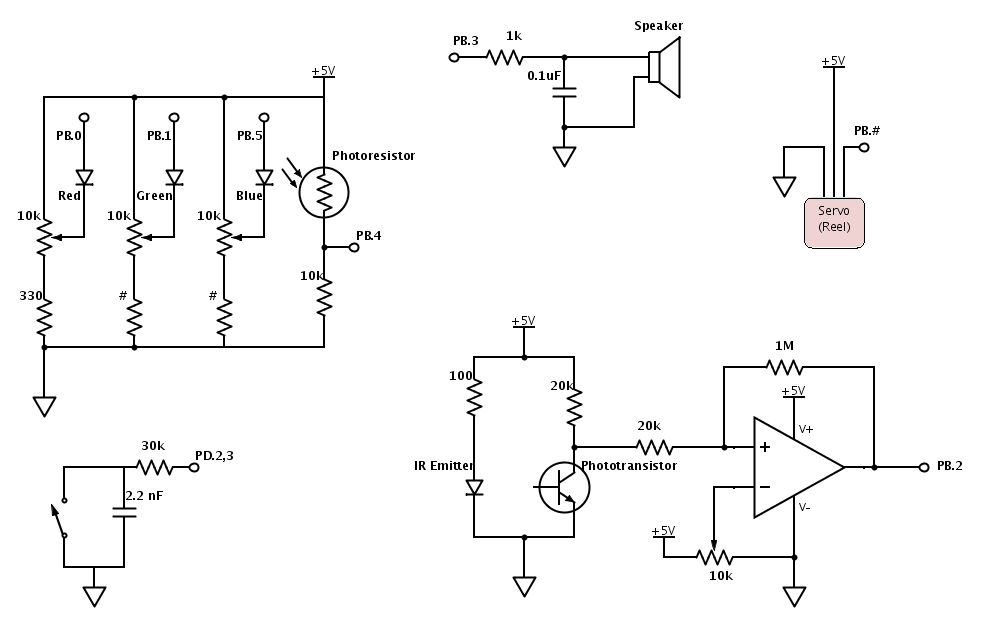
To prevent damage to the LEDs, each LED is in series with a 330 ohm resistor, which limits the current to a maximum of about 15 mA (Vcc=5V, 5/330=0.015). Each LED is also in series with a 10kOhm trimpot to allow for brightness level adjustments such that the photoresistor's response to each color (when shined against black or white surfaces) is comparable. Although the 10kOhm trimpot may seem excessive, it turns out that the control it provides over the brightness levels is not coarse. Furthermore, certain types of variations in RGB values can be more accurately handled in software, so it is unnecessary to have extremely fine control here.
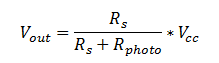
Photoresistor
The photoresistor acts as a variable resistor which forms a voltage divider with a set resistance of 10kOhm. Since the photoresistor's resistance decreases as light increases, measuring across the 10kOhm resistor provides more intuitive data to work with (more light, higher voltage, higher ADC reading). Although the photoresistor datasheet says that its resistance ranges from 80k to 200k under some sort of illumination, after testing, we found that the resistance could go much lower when the LEDs are shining onto it (can reach 3k). After some testing, we decided that 10k was an appropriate resistance value for the resistor in series. The voltage that the ADC reads is specified by the following equation, where Rs=10k, Vcc=5, and R_photo ranges from 80k to 200k in light:
Sound to Speakers
Direct digital synthesis outputs a PWM signal, which needs to be low-passed first before connecting it to the speakers. The external RC low-pass filter takes as input the PWM signal generated by the MCU through Port B3. The resistor value must be large enough so that the port pin is not loaded and small enough to be below the input resistance of the speaker. Furthermore, the RC time constant must be about 6 times the period of the PWM because the RC filter acts as an integrator in that frequency range and will translate the PWM signal to a sinusoidal signal. The 0.1uF capacitor and a 1kOhm resistor satisfy these requirements.
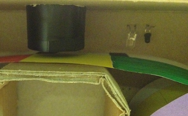
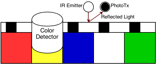
IR Sensor
To ensure that color detection occurs when the color patch of interest is right below the color detector unit, the color tape player has an IR emitter and sensor subsystem. The infrared emitter shines light onto a section of the color tape, which contains strategically placed black markings on white paper. When the emitter is above the black marking, light is not reflected to the phototransistor, which turns off the transistor and the output voltage goes high. The signal from the phototransistor is connected to a comparator to produce fast, logic-leveled output swings ranging from 0 to 5 V. The 10kOhm trimpot sets the comparator threshold, and the 1M resistor sets the hysteresis. Hysteresis makes the rising/falling edges of the waveform less sensitive to noise because the comparator does not immediately transition from output low to output high (or vice versa) when it sees the input voltage cross a particular threshold voltage. The logic-leveled output swings trigger an ISR on the rising edge (discussed in the software).
Debouncing
We implemented button debouncing in hardware rather than software. When a mechanical button is pressed or released, the switch may bounce several times rapidly before settling to its final state. In our code, a non-debounced button may trigger the ISR multiple times, which causes incorrect results. By low-pass filtering the button signal with a small RC constant, the speed of the rise and fall of the button signal is maintained while the high frequency bouncing is filtered out. A 2.2 nF capacitor across the button satisfies this requirement - assuming 30kOhm pull-up resistance.
Things We Tried
We tried to trigger the IR sensor by hole punching the color tape at regular intervals such that IR light only passes through the tape to the phototransistor when the two components are directly aligned with the hole. When we tested this out, the IR light was able to pass through the paper. In addition, when the servo unrolls the paper, the paper would sometimes deviate from the straight path. When this happened, the IR sensor would miss the hole punched area and not trigger when it should.
We initially attempted to debounce the button in software, but this resulted in extra time maintenance in the sound generation ISRs and additional code in the button ISRs. Extra code in ISRs is always undesirable, so eventually we decided to implement debouncing in hardware. Adding the low-pass filter to the button signal proved to be much more reliable and did not require extra code.
When working on the sound generation, we attempted to combine the voice code with the harp/retro/violin code in the DDS ISR. The voice produced was slightly distorted and had a very high-pitched noise artifact in the background, which convinced us that timing constraints were not being met. Thus we designated a separate ISR for the voice generation.
Results
Speed and Accuracy
Overall, our color to sound device met our expectations and works well. After careful calibration, our color detector can detect colors consistently. Unfortunately, even with ideal LEDs and photoresistor, the texture and material of the colored surface may reflect light in unpredictable ways that affect the accuracy of the measurements. For example, coloring a paper with orange highlighter returns more blue than red and green even though orange consists of the least blue.
The colors that we chose to detect for the musical tones (excluding black, white, and orange) are either primary or secondary colors, which have distinct RGB content and are least prone to error. The threshold levels were determined after many rounds of testing with various colored materials. The trial and error nature of this process was unavoidable due to the aforementioned variability in the colored materials. Nevertheless, below are a few of the RGB values that we recorded from Crayola markers on white paper, which ended up being the type of surface we used for the color tape reel when the device is used in color tape player mode:
| Color | Red | Green | Blue |
|---|---|---|---|
| Black | 30 | 28 | 33 |
| White | 178 | 165 | 168 |
| Red | 151 | 30 | 27 |
| Yellow | 101 | 111 | 35 |
| Blue | 2 | 15 | 145 |
As mentioned earlier, we made a hardware tradeoff when we decided to use a photoresistor for its human-like spectral curve despite its slow rise and fall response times. The bottleneck to our color detection speed is thus the response time of the photoresistor. The datasheet states 60 ms rise time and 25 ms fall time, but actual testing revealed 20-50 ms rise time and 20-30 ms fall time. After doing more testing, a delay of 40 ms between each RGB reading is enough to give accurate results. In total, color detection takes a little more than 120 ms. This is not too slow because it gives enough time for a musical note or word to play out.
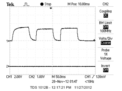
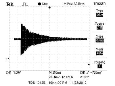
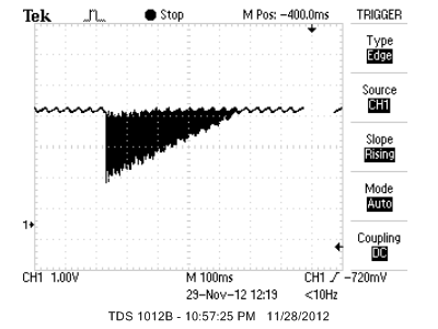
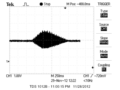
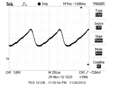
The spoken colors created using decompression on the fly is easily recognizable, though the quality is not clear, which is to be expected. In our opinion, the instrumental sounds produced are realistic. Linear ramping for some of the instruments creates the realistic decaying effect that we are trying to achieve. Below are some of the waveforms from the musical instruments.
Below is a table of the accuracy of the frequencies generated by the DDS:
| Expected Frequency (Hz) | Measured Frequency (Hz) |
|---|---|
| 587 | 588 |
| 659 | 661 |
| 740 | 741 |
| 784 | 785 |
| 880 | 883 |
| 988 | 987 |
| 1109 | 1111 |
| 1174 | 1176 |
As shown above, the sound waves generated by the DDS is very accurate (average percent error of 3.7%) and any slight inaccuracies are undetectable by the human ear. For the string sound generated using Karplus-Strong, the calculated delays using the equation from the "Background Math" section were not very accurate, so we had to find the delays for the desired pitches through trial and error.
Safety
To make sure that our design is safe for the user and that the user does not accidentally short any components, we keep all wires and electronic components inside the box. We also hold down loose wires with electrical tape. The user will interact with the color detector unit the most, so we took special precautions by applying heat shrink tubing to open wires coming out of the detector. The device does not have any sharp edges capable of harming the user since the structure is made almost entirely of cardboard.
Interference
The device does not interfere with other people's designs in major ways. The only source of interference is the sound produced by the speakers, which we kept at a tolerable level while testing.
Usability
This system can be used for both practical and entertainment purposes. Colorblind people can use the device as a tool to determine the color of objects. Toddlers who are still in the process of learning the basic colors can use the device as a colorful, educational toy. In fact, people of all ages who are interested in music and color will find this device to be a fun, interesting gadget.
Currently, the color detector unit can identify nine colors, which some visually impaired people may find to be sufficient, but one thing we can do to make it a more helpful device is to increase the set of identifiable colors. Although we put in our best effort to make the device generally safe and usable for most users, if we were to offer this product to younger children, we would need to make the device even safer.
Conclusions
Our Color to Sound Player fully met our initial expectations - it can detect nine different colors consistently when calibrated correctly and the instrument sounds produced are realistic. The accuracy of the sound frequencies is sufficient for the human ear, and the spoken colors generated through voice synthesis is relatively clear given that it is decompressed on the fly in less than half a second. If given additional time, we would expand the set of detectable colors and include additional instrument sounds. Since the device was meant to be very user-interactive, we would probably add more features to make the product more user-friendly. For example, we considered adding other musical scales and perhaps a note recording and replay capability.
Intellectual Property
We based our DDS sound generation on the technique used in ECE 4760 Lab 2. In order to generate string sounds, we referred to Bruce Land's Karplus-Strong MATLAB code and implemented the algorithm in C. The code to generate voices was borrowed from Bruce Land's page on "Speech Generation", and to generate the voices, we used the Text-to-Speech Demo from AT&T. Throughout development of our code, we did not use code from the public domain, we did not reverse-engineer a design or have to work with patent or trademark issues, and we did not have to sign any non-disclosure to get sample parts. Our project does not have any other legal considerations. In terms of patent opportunities, we will probably not pursue any since the concept of color detection and sound generation is not a completely novel idea - although we have yet to find a color to both speech and instrumental tone converter, web searches show that there exist color to speech converters specialized for the visually impaired and color to music toys.
Applicable Standards
Our project's C code abides by the C Language standards set by the ANSI (American National Standards Institute). Following the IEC (International Electromechanical Commission) 60825-1 standard for "Safety of Laser Products", the brightness of each of our LEDs was kept at a low enough level to not cause damage to the eye yet still meets our needs. We also followed the IEEE ethical standards (see next section).
Ethical Considerations
During the course of developing our Color to Sound Player, all efforts were made to comply with the IEEE Code of Ethics. As the user interacts with the color sensor most often, we took extra measures to ensure safety in its use by reducing the amount of exposed wires through heat shrink tubing. To prevent cluttering of the various subsystems, the majority of the project is fixed into place inside a box. This will not only reduce the chance of shorting wires but also allows for ease of transportation of the system as a whole.
Over the span of the project, the code supporting the color sensor has evolved to better approximate the color being sensed. After much testing, we have concluded that our sensor can differentiate between a fixed set of colors. Based on the experiments we have done, we make no claims that our color sensor can perform with 100% accuracy on all types of surfaces, but instead we have realistic claims that the sensor performs with a high level of consistency for the specified set of colors and some pre-tested surfaces.
Throughout the development of the various sound generation code, we borrowed algorithms and code from links on the Cornell ECE 4760 website, such as the Karplus-Strong algorithm for generating plucked string sounds. The use of these ideas has been documented within this report.
Acknowledgments
We would like to thank Professor Bruce Land for his great suggestions (such as the inclusion of voice generation) and help with debugging. Also, we would like to thank the TAs for helping to resolve various technical issues that we had. Our project would not have been possible without the greatly appreciated support of the course staff.
Appendix
Code
sound.cuart.c
uart.h
header_red.h
header_orange.h
header_yellow.h
header_green.h
header_aqua.h
header_blue.h
header_violet.h
header_white.h
header_black.h
Parts List
| Part Name | Source | Unit Cost | Quantity | Total Cost |
|---|---|---|---|---|
| Mega1284 | 4760 Lab | $5.00 | 1 | $5.00 |
| 9V Power Supply | 4760 Lab | $5.00 | 1 | $5.00 |
| White Board | 4760 Lab | $6.00 | 1 | $6.00 |
| Small Solder Board | 4760 Lab | $1.00 | 1 | $1.00 |
| Continuous Rotation Servo | All Electronics | $12.99 | 1 | $12.99 |
| C503B-RAS-CY0B0AA1-ND | Digi-Key | $0.15 | 1 | $0.15 |
| C503B-GAS-CB0F0791-ND | Digi-Key | $0.24 | 1 | $0.24 |
| C503B-BAS-CY0C0461-ND | Digi-Key | $0.21 | 1 | $0.21 |
| Green LED | 4760 Lab | $0.00 | 5 | $0.00 |
| PDV-P9006-ND | Digi-Key | $1.51 | 1 | $1.51 |
| IR Emitter | 4760 Lab | $0.00 | 1 | $0.00 |
| IR Sensor | 4760 Lab | $0.00 | 1 | $0.00 |
| Jumper Wires | 4760 Lab | $1.00 | 11 | $11.00 |
| 10k Trim Pots | 4760 Lab | $0.00 | 4 | $0.00 |
| LM358 | 4760 Lab | $0.00 | 1 | $0.00 |
| Push Buttons | 4760 Lab | $0.00 | 3 | $0.00 |
| Speakers | 4760 Lab | $0.00 | 1 | $0.00 |
| Resistors/Capacitors | 4760 Lab | $0.00 | 18 | $0.00 |
| Cardboard Pieces | (Scavenged) | $0.00 | -- | $0.00 |
| Total Cost | -- | -- | -- | $43.10 |
Task Distribution
| Deyu | Joint | Kevin |
|---|---|---|
| Voice Synthesis | Harp & Retro Instruments | Violin |
| Karplus-Strong | Color Detection | Website |
| Soldering | Construction of Device | Instrument/LED case statements |
| General debugging | ||
| Documentation |
Schematics
Datasheets and Websites
Red LEDGreen and Blue LED
Servo
Photoresistor
Mega1284
Atmel
digikey
AllElectronics
References
Color DetectionSpeech generation
Karplus Strong
Karplus Strong picture
Text to Speech