We initially wanted to create a version of blackjack where instead of the cards being virtual, a camera would take a picture of a player card. Then, it would send the data to Matlab which would do image processing and recognition. Matlab would send the data to the MCU which would use it as input for a blackjack game. Unfortunately, we never got our camera working. Thus, the initial design we present is without a camera. After that design, we discuss the camera, how it works, and why we think we could not get it working.
Our current design constists of an Atmel ATmega1284p 8-bit microcontroller and a deck of playing cards.
Our original design consisted of an Atmel ATmega1284p 8-bit microcontroller, an OV7670 camera module, two PF35T-48 Stepper motors, a timing belt, two gears, and a deck of playing cards.
High Level Design
Our original design involved having a camera take a picture of a playing card and using image reconition in Matlab to determine what card was placed. However, we were never able to get the camera fully functional. Therefore, we took a picture with a cell phone camera and stored the images in a file in the computer. Then, to randomly pick a card, we chose a random file and ran the image reconition algorithm on that file. This way, we demonstrated that we understood how to do image recognition. Matlab then sends the card information to the MCU which runs the blackjack game.
The Blackjack Game
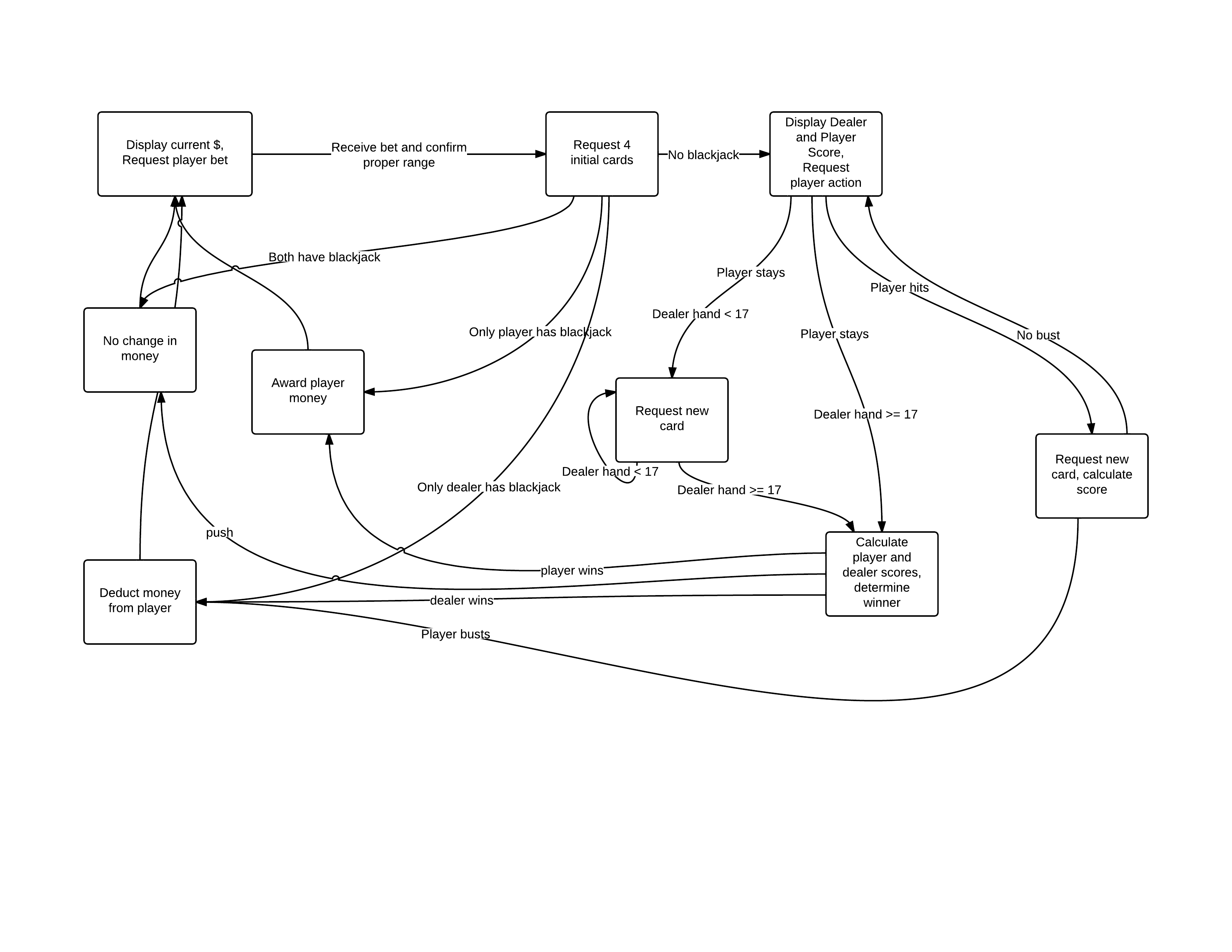
The blackjack algorithm is straightforward as far as blackjack algorithms go. The player starts off with $500 fake dollars. The basic algorithm can be seen in the below state diagram. We also added double down as an option where the player bets twice as much but only gets to hit once. This option is removed from the state diagram for the purpose of clarity. A challenge of the algorithm was handling aces. We designed them so an ace will count as 11 unless that puts the player score above 21 in which case the ace counts as 1. We keep track of who has an ace with a boolean variable. If the player or the dealer gets a second ace, it automatically counts as a 1.
Matlab
Matlab was vitally important to our project. It served two purposes. First, it was used to do image processing and recognition. Second, it was used in place of PuTTY for serial communication with the MCU.
Image Processing and Recognition
Our OCR was set up to do handle the 144x176 images (in QCIF format) and perform recognition tasks. In lieu of usable images from the camera, MATLAB could also take in JPEG images and transform them into the proper format. MATLAB does this by loading the specified .jpg image. Next, it applies thresholding to turn the picture into a binary (black and white) image. The image is then trimmed on top and bottom until its height and width are in the 144x176 ratio. Next, it resizes the image down to 144x176 with equal scaling (because the height and width are in the proper ratio).
Once the image is in the proper format, the characters making up the rank and suit of the card is extracted. The white space to the left, right, top, and bottom of the image is removed. It does this by looking for the furthest row or column (as applicable) with a black pixel. We were originally planning to do image recognition by determining the ratio of black pixels to white in different areas of the image. This became problematic as many characters in the rank of the card have similar pixel ratios (there was also a degree of variability due to each picture). Otherwise, 6 and 9 would be near indistinguishable as would a few other numbers.
Instead, to determine rank, 4 lines were drawn across the image. One was a vertical line that divides the image in half. The other three were horizontal lines at 1/4, 1/2, and 3/4 the image height. As each line was drawn, it observed any variation in color. By marking the amount of color variations for each line, a "signature" of the rank could be determined. Most characters had a unique signature. However, 3 and 5 required a special handler to determine where their upper half of the character lies. Similarly 6, 9, and the Queen required another handler to distinct the three.
The suit was determined by cropping the suit character and performing a pixel ratio test. Unlike the rank characters, the suit characters had fairly reliable pixel ratios. By comparing the ratio of black pixels to all pixels in the cropped frame, the suit could be determined. The ratio for hearts was > 0.53. For diamonds it was < 0.44. For clubs it was 0.44 < x < 0.495. For spades it was ~5, and it was used for all ratios between 0.495 and 5.3. (Note these numbers are the ratio of # of black pixels/total # of pixels.)
Aces proved difficult because our casino-quality cards had a black corner above the characters. This black corner was removed during extraction by cropping out the large contiguous black section. A special case was created for the Ace of Spades because the face of the card has an ornate design. This made it impossible to crop the image to extract the characters. Therefore, in this case, rank and suit was given the Ace of Spades.
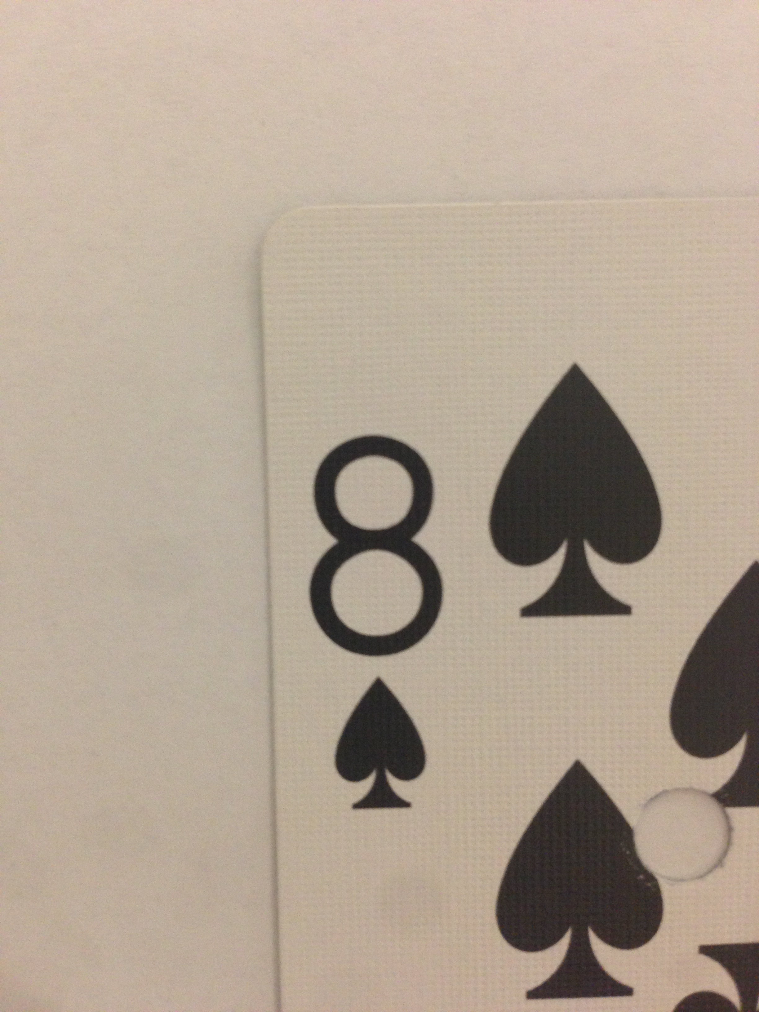
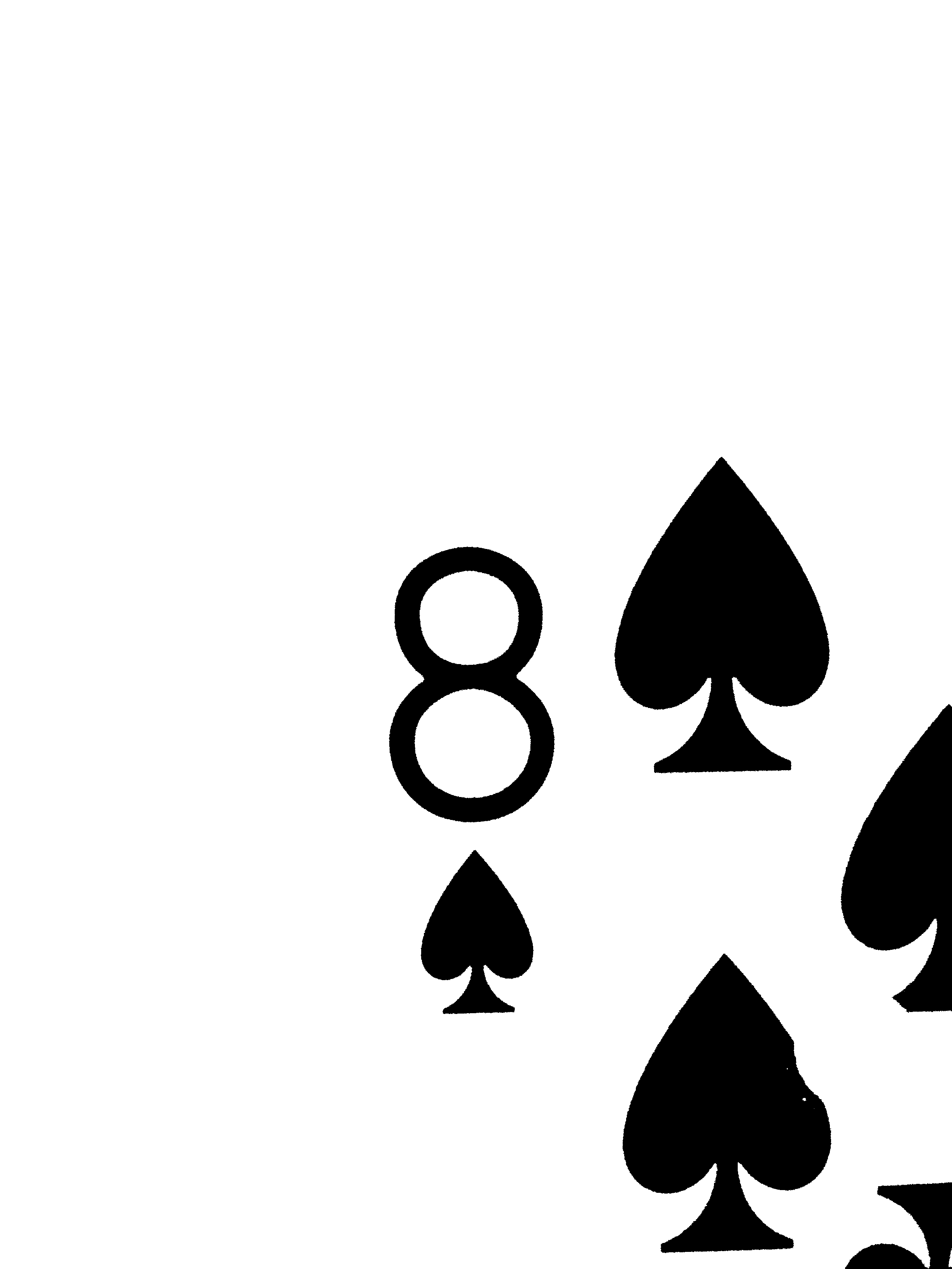
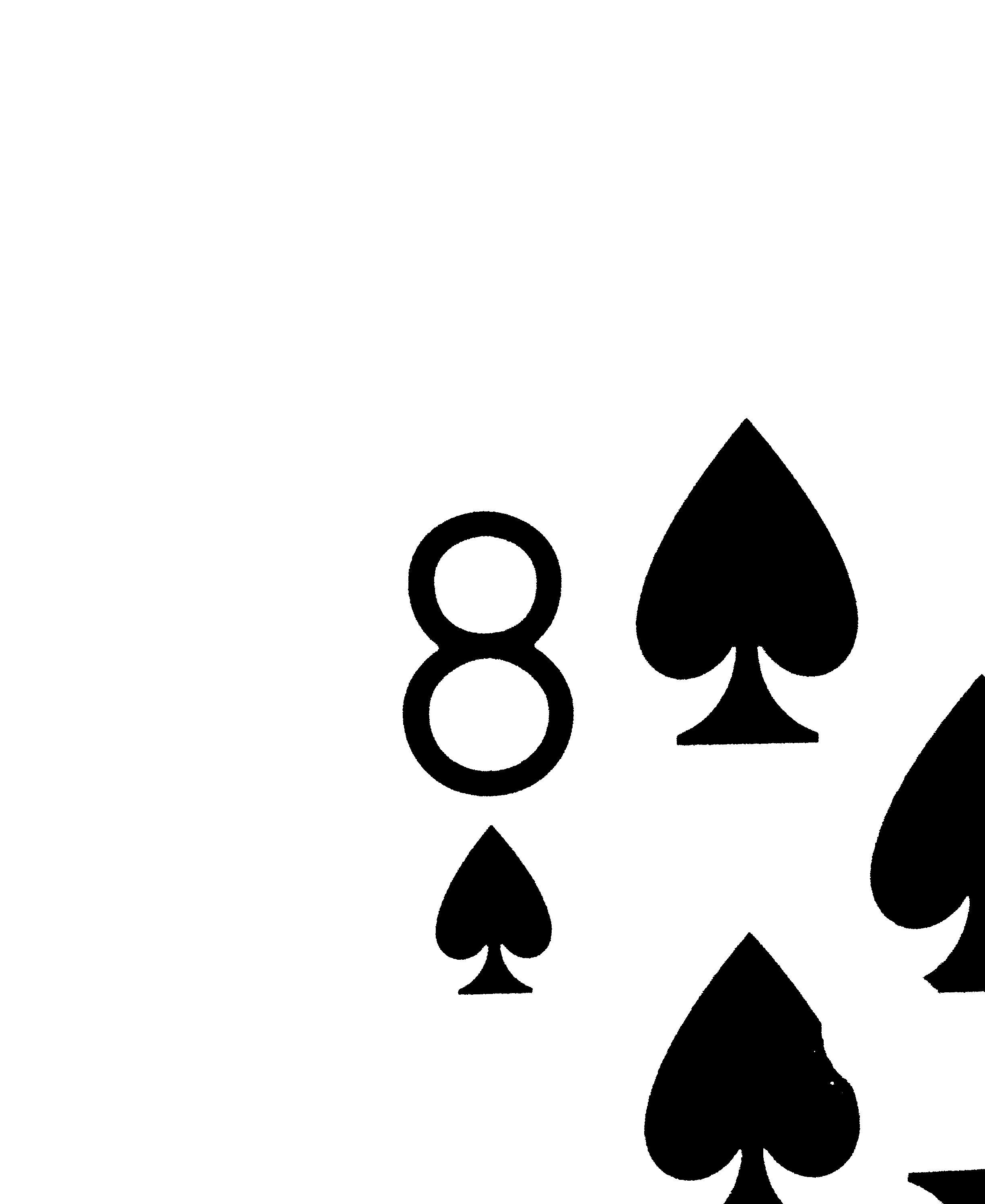
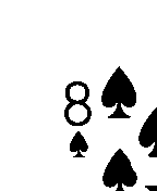
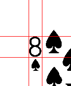
Below are 10 pictures demonstrating the image processing and recognition process. The first picture is the original from the camera. The second is the threshold. The third image is trimmed. The fourth is resized. The fifth demonstrates cropping. The sixth image shows the cropped rank. The seventh image shows how we get the suit (note that it is the box below the rank box). The eigth image demonstrates breaking up the image into different sectors to get the color variations. The ninth image demonstrates cropping the suit more. The tenth image is the cropped suit.
![]()

![]()


Serial Communication in Matlab
Code for setting up and using serial with Matlab is very simple and requires specifing the port, baudrate, parity bits, data bits, and flow control. We also specified a timeout. Putty has a key advantage over Matlab in that it automatically displays text and data it receives. Matlab has to have been told to scan for data on the port. For Matlab, we had to set up a while(1) loop. The first thing it does is send a signal to the MCU alerting the MCU that Matlab is ready to receive data. As soon as it sends this signal, Matlab runs fscanf to scan the port. The MCU, which runs fscanf before every fprintf, receives the signal from Matlab and prints whatever data it needs to print after a short delay. Matlab will then do one of three things. If it receives "irq", it knows that the MCU needs data (either the player's bet or the player's move). If it receives "r_#", it translates that into select image number "#", do image processing on the .jpg file, and sends what it thinks the image is to the MCU.
Camera
The OV7670 is a camera module that caused a great deal amount of trouble for us. It has pins for 3V power supply, ground, SDIOC which is the SCCB clock, SDIOD which is the SCCB data, VSYNC, HSYNC, PCLK, XCLK (an input for the system clock), 8 data pins, a RESET, and a PWDN pin. XCLK has to be above 8 MHz for the camera to run correctly. While software was available from the previous labs for the C3088, we chose OV7670 because we initially had budget constraints and the OV7670 was cheaper. The camera operation is theoretically very simple. First, it is a video camera so there are many frames a second. The frame rate is set by an external clock. The camera outputs three different timing clocks for data output: PCLK, HREF, and VSYNC. VSYNC is high in between frames and low during data transmission. HREF corresponds to horizontal lines. HREF is low between the last byte and the first byte of a new line. HREF going high signals the start of a new line. PCLK relates to pixel timing. PCLK going from high to low signals the start of a new pixel. This information is summed up in the two images below.
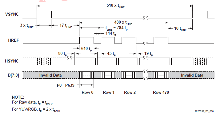
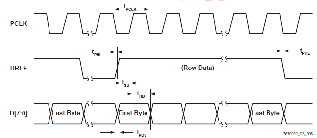
The above images are from the OV7670 data sheet.
The OV7670 is programmed with SCCB communication protocol which is a minor variation of I2C. There are a vast amount of registers that control a wide array of video configuration options. These registers are enumerated in the data sheet.
SCCB uses two wires SIOC is the signal clock and SIOD is the data wire. The start of data transmission is signalled by SIOD being pulled from a floating tri-state to low. SIOC must be high during this assertion. Data transmission is signalled to stop when SIOD is pulled high while SIOC is high. Camera write is achieved by sending the start signal which includes the 'write' register # (0x42 in this case) followed by the register # we are writing to followed by the data. Camera read is achieved by sending the same start signal, sending what register we're reading from, and then sending the start signal again, but this time with the 'read' register # (0x43). We know we achieved correct signalling because we were able to read register 0x0A (which stores the device ID number) correctly as 0x76. Furthermore, we were able to write data to a control register and then correctly read it back.
Our plan to read the data was to read 1 pixel for every 4 rows and for every 4 columns. We chose this because we set up the camera for QCIF format which is 176x144 (both numbers are divisible by 4). We chose to do 1/16th of the image because the microcontroller has limited storage. We also attempted to set the camera to YCbCr (YUV) color format. In YUV, 2 bytes form 1 pixel and 4 bytes form a macropixel. Every macropixel shares color data (U and V). The reason is that the human eye is much more sensitive to intensity (Y) then color. So we were going to only same the Y bytes in order to get a greyscale image.

http://en.wikipedia.org/wiki/YUV#Y.27UV422_to_RGB888_conversion
Unfortunately, we were not able to get the camera working. Because we could correctly read the device ID register, we know we did not have a problem with SCCB. Therefore, the problem either came from not setting the control registers correctly or not understanding how the data was output. In one experiment, we displayed every single byte consecutively (with the lens cap on) and got data along the lines of "128 0 0 0 128 128 0 128 128 0 0 0 1 0 128 0 128 128 ..." Seemingly random data with no discernable pattern. Therefore, we believe we did not properly configure the camera. Unfortunately, there were no easy to understand demos online.
Stepper Motors
Initially, we planned to use the stepper motors to drive a pulley that would move the camera back and forth so it could take pictures of all the new cards placed. We never got the camera working, but we did get stepper motors working, so we are posting that information here.
A stepper motor works by sending a series of pulses to the different inputs of the device. Each input generates a small magnetic field which causes the internal magnet to rotate a very specific degree.
Physical Operation of Stepper Motor. (By Wapcaplet; Teravolt.Teravolt at en.wikipedia [GFDL], via Wikimedia Commons)
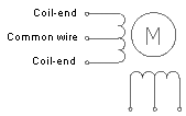
The motor we used in our original design was the PF35T-48 which is unipolar, two coil model.
 "(By Yegorius (Own work) [GFDL or CC-BY-SA-3.0-2.5-2.0-1.0], via Wikimedia Commons.)"
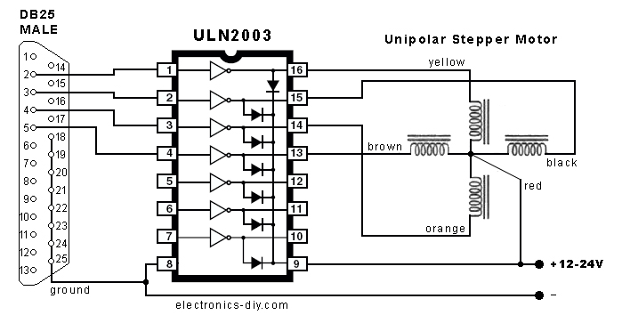
We drive the motor by wiring 4 output wires from the MCU to a ULN2003. We then wire the 4 corresponding outputs of the ULN2003 to the four coil wires the stepper motor. Below is a sample wiring of the ULN2003 to a stepper motor.
There are multiple methods of driving the stepper motor. To elaborate, we can see that in the above gif, each coil is activated 1 at a time. However, if we overlap coil activation, we can get a more finely tuned step. So if we have 1 activated, then 1 and 2 activated, then 2 activated, we can see that the internal gear will have a step between coil 1 and coil 2. This is shown in the below picture.
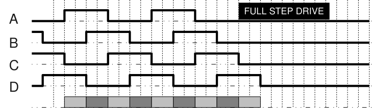
"Full Step drive pattern, where A and C are the two coil-ends of one phase, and B and D are the ends of the other. (By Misan2010 (Own work) [CC-BY-3.0], via Wikimedia Commons)"
Standards Used
For communicating with the camera we used SCCB. SCCB is a slightly modified version of I2C. In fact, it is so slightly modified that the i2cmaster.h file by Peter Fleury was sufficient to communicate with the camera.
Intellectual Property
The game of blackjack is in the public domain as are all the symbols and terms involved. We are revealing all of our code for anyone to use.
Results
Accuracy
Speed
Using Matlab for UART required adding additional delays in the sends and receives, so this slows our program down significantly. However, it is reasonable to expect 1 round of blackjack per minute with our software.
Safety
Since all of our project was done in software, there are very few safety concerns.
Usability
Since the communication and processing are relatively fast, this is a decent way to play blackjack.
Conclusions
Results vs. Expectations
We are fairly disappointed with our results. We expected to have the camera up and running in a lab period, but instead we wasted more than a week and a half working with it. This also meant a lot of our other work with the stepper motors that would move the camera was wasted. Furthermore, we initially planned to be able to pick up and move the cards ourselves with a vacuum pump and suction cup. The pump worked fine, but we were never able to come up with a solution to raise and lower the suction cup. This, again, was wasted time. If we had decided to do our final project the way it currently is from the beginning, we would have been done much, much sooner.
That being said, we are thrilled with our blackjack algorithm and our OCR algorithm. Both work outstandingly well as expected. If we were to do the project again, we would have purchased a camera that we knew other people got working.
Conforming to Standards
We were able to communicate with the camera. This means that we successfully conformed to the SCCB standards of the camera.
Intellectual Property
Our design poses no intellectual property problems. All the information is in the public domain. When we used the camera, we used I2C code from Peter Fleury and modified C3088 code from the FaceAccess project. However, that is not included in our final code. The image recognition algorithm we used was of our own design.
We will try to publish our design so everything we did will be in the public domain.
Ethical Considerations
There were no major ethical considerations for our project. We made sure to be courteous to others and keep our lab space clean and minimal. We cited all contributions and inspirations. There were no major safety issues.
Legal Considerations
The only major legal consideration is that gambling is illegal. Fortunately, we used fake currency so that is not a concern. Additionally, if the system were made portable, it could be modified to give gambling advice, which is illegal in most states.
Appendices
A. Source Code
Source files
The following source files are ones borrowed for the project. They were used for camera communication
Header files
Matlab scripts
Pictures of all the cards
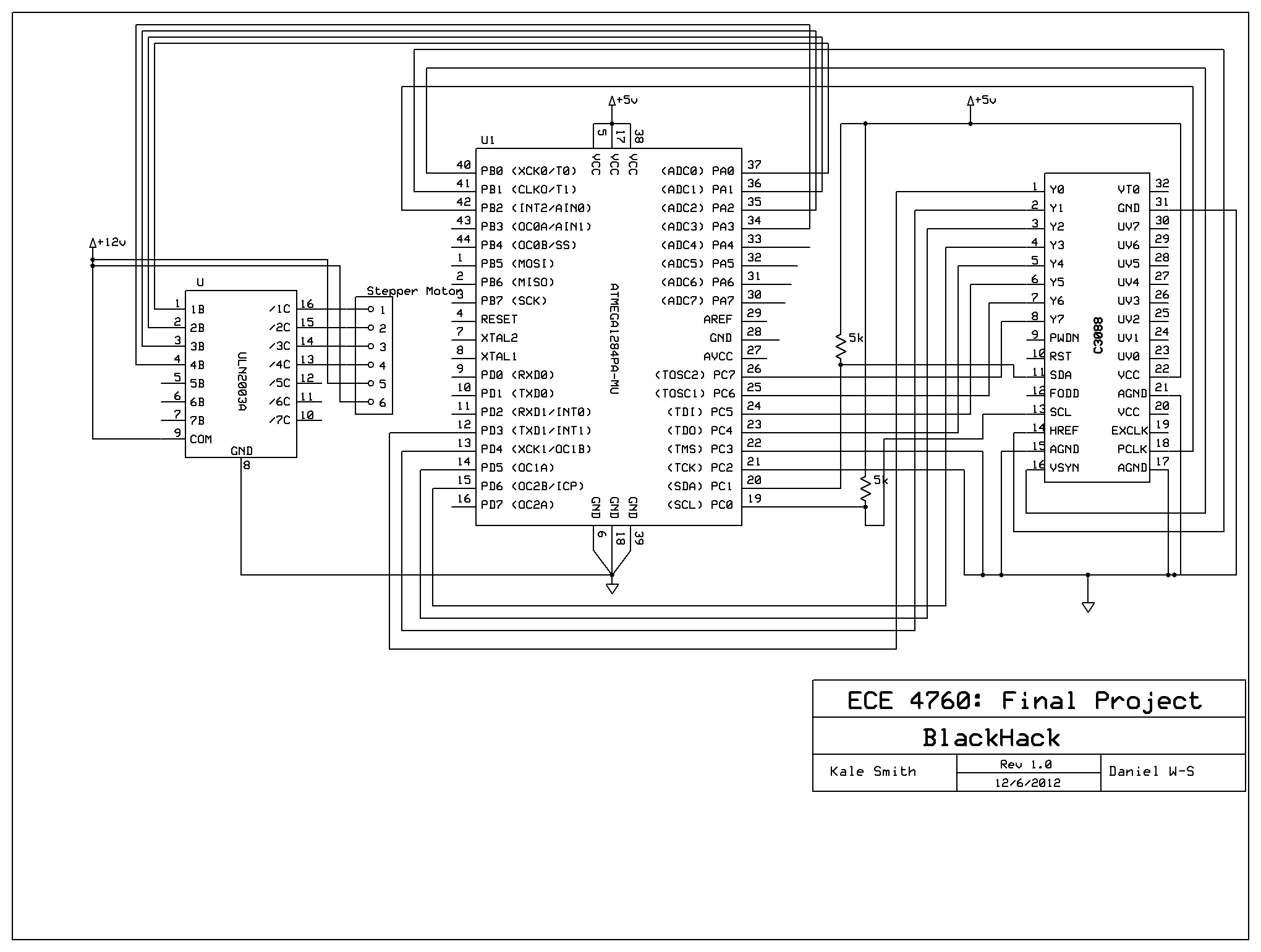
B. Schematics
For our schematics section, we are uploading the schematic as it would look if the camera was working. However, since the camera is not working, neither the camera hardware nor motor hardware is necessary--simply UART is needed. We provide the schematics to demonstrate that we understand what is required and to provide a template for future projects.
For the camera, we used the C3088 part because there was none for the OV7670 and the parts have similar pin names.
C. Parts List
| Part | Source | Unit Price | Quantity | Total Price |
|---|---|---|---|---|
| ATmega1284p (8-bit MCU) | ECE 4760 Lab | $5.00 | 1 | $5.00 |
| OV7670 Camera Module | Ebay | $7.99 | 0 | $0.00 |
| ULN2003A | ECE 4760 Lab | $0.00 | 0 | $0.00 |
| Deck of Cards | Owned | $0.00 | 1 | $0.00 |
| Total | $5.00 |
D. Tasks
This list shows specific tasks carried out by individual group members. Everything else was done together.
Daniel
- Wrote project report
- Built camera mover (not used)
Kale
- Wrote OCR Matlab code
- Wrote blackjack logic
References
This section provides links to external reference documents, code, and websites used throughout the project.
Datasheets
- ATmega1284 (8-bit MCU)
- OV7670 (Camera Module)
- SCCB (Serial Camera Control Bus) (I2C for the Camera)
Reference Code
We referenced preious projects image sensor code to create our camlib.c library.