Introduction top
"A device that tracks sound impluses with a three microphone array"
We designed and build a 2-dimentional Acoustic Impulse Marker system which is capable of detecting a sharp sound anywhere in its vicinity and precisely marking its source vector with a servo based pointer. Our system has a full 360 degree range, and is extremely effective at marking the source of sharp sounds to within 5 degrees of accuracy. We were able to accomplish this using a 3-microphone array and an ATmega1284p microcontroller which detects the acoustic delays between the microphones and calculates the sound’s source vector. The microphone signals are passed through an 8 stage analog system in order to convert them to a binary signal, indicating when each of them is triggered by a sound. Those 3 binary signals are analyzed for their time delays and the microcontroller selects the best 2 microphones to calculate the exact angle in which the sound originated from. The servo motor is then controlled so that it turns a pointer exactly in that direction.
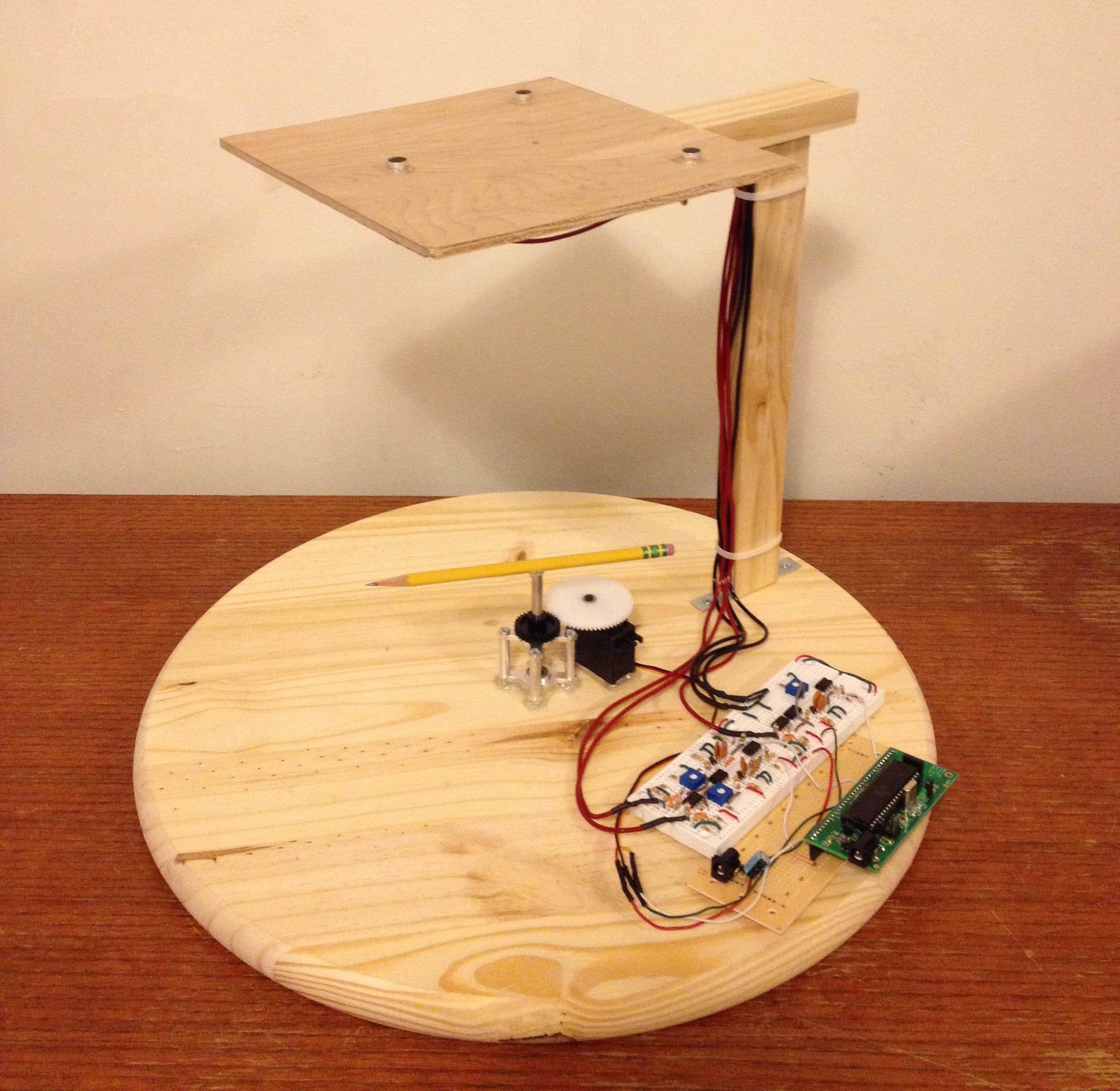
Finished AIM System
Design top
Rationale
We wanted to explore the idea of microphone localization based on time delays. The speed of sound in air is roughly 340m/s, which is slow enough to measure time delays between offset microphones using a microcontroller. We measured these time delays across 3 microphones and used basic trigonometry to calculate the angle from which the sound originated from. In order to visually mark the source of the sound, our system controls a centrally mounted servo motor which spins a pointer to the acoustic source.
Background Math
All calculations use the SI units of meters, seconds, and degrees Celcius. All angles however, are measured in degrees.
Speed of sound in Air:
V = 331.3 + (0.606*T)
The speed of sound in air is approximated by this linear formula, directly proportional to the ambient air temperature.
Angle Calculation:
Theta = (180/pi) * arcsin((delay *speed_sound) / mic_distance )
Using the fixed values for “speed_sound” and “mic_distance”, we can use the sound delay time in this formula to calculate the relative angle as a value between 0 and 90 for two specific microphones.
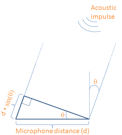
Two Microphone Angle Model
Servo Control:
OCR0A = round(((degree*(servo_max - servo_min) / 180) + servo_min) * 62500) – 1
Using the calibrated pulse widths for “servo_max” and “servo_min”, we can input any desired degree between 0 and 180 to generate the corresponding value for the timer compare match register, which will set the duration of the servo control pulse.
Logic structure
Each microphone is processed though a precise analog circuit to convert it to. This binary signal represents the state of each microphone, either triggered by a sound pulse or not.
Once the microphones are interpreted as binary states, those values are read as inputs by the microcontroller. These inputs control a state machine, which requires all 3 microphones to start in the OFF state and then trigger in succession within an appropriate amount of time to accept it as a valid pulse. When a valid sound pulse is acquired, all the timing values are stored as variables and a variable flag is set high to indicate that the data should be processed to calculate the source angle.
During the calculation, the system determines which pair of microphones lies most perpendicular to the sound source. This gives us the most accurate calculation possible. Then the time delays between those microphones are used to compute the sound source angle relative to those two microphones.
Finally, the relative angle is converted into an absolute angle between 0 and 360 degrees around the entire system. This absolute angle is converted into a calibrated PWM signal, which is passed as an output directly to the servo motor. The servo motor moves to the angle corresponding to its signal, and thereby points in the exact direction that the sound pulse originated from.
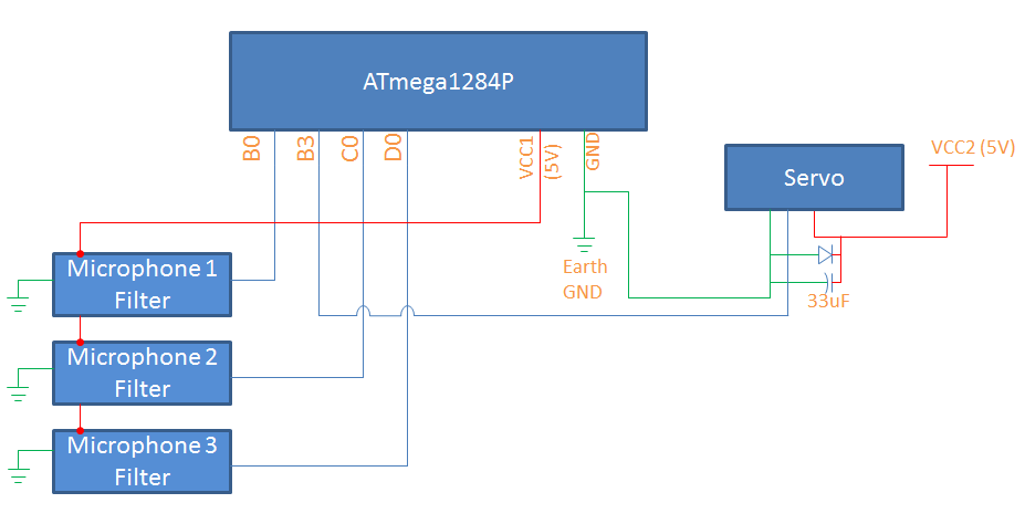
Block Diagram of Finished Circuit
Hardware/Software tradeoffs
The core of our system is hardware based analog circuit, which filters, amplifies, and processes the sounds obtained from the microphones. By utilizing hardware for this, we are able to high frequency signal processing without taxing the microcontroller. Also, we remove the need to use the relatively slow ADC of the microcontroller by processing all the analog signals in hardware and converting them to binary digital pulses. However, the main tradeoff here is that the analog hardware limited our accuracy in a way that is very difficult to measure. Every stage of the circuit has real world inefficiencies and tolerances, which could accumulate in minute error. No matter how fast or thorough our software system is, it can only work with the values received from the analog hardware.
The software system is a great tool for logical processing and control signals. All of our computation and servo control is done on the microcontroller in software. This gives us a fixed limit for speed, precision, and memory. However, the benefits of the software include very high reliability (excluding any designer coding errors), and very well defined constraints on speed, precision, and memory which allows us to analyze the performance capabilities of our software system accurately.
Standards and Patents
Our project is not based on any major standards from IEEE, ISO, or any others. However, the system we are designing is truly a method and apparatus for sound source direction detection. There are many patents in the realm of sound localization ranging from military applications, signal processing algorithms, and even consumer products such as videoconferencing and gaming systems. We developed this system independent from any published work on this topic, but we realize that we are not the first to develop such a system.
Hardware top
Mechanical Design
The physical system we designed contains a wooden base for mounting the servo and electronic hardware, with an elevated platform to hold the 3 microphones directly above the center of the base. The physical structure was made using only wood, L-brackets, and screws.
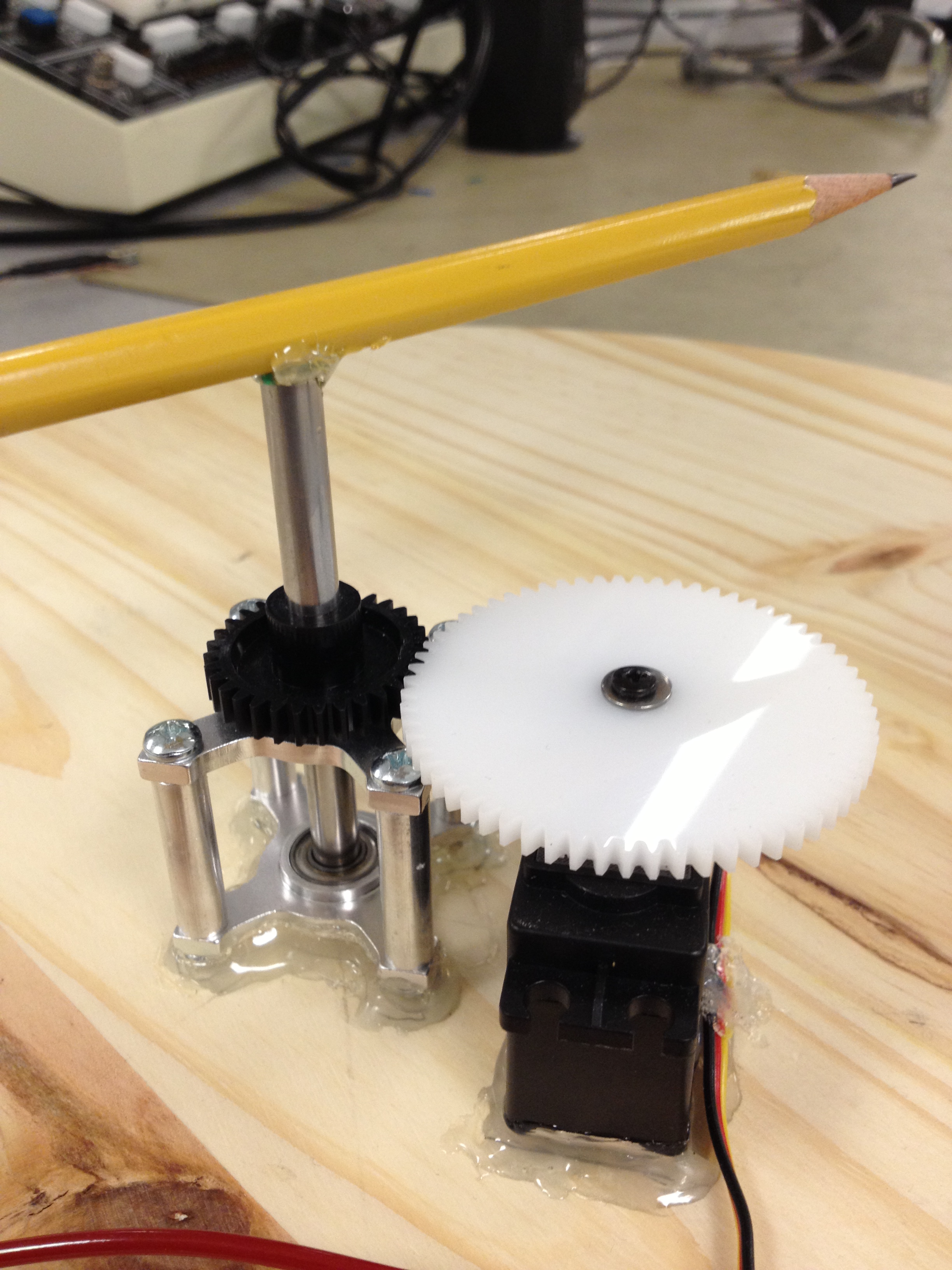
Mechanical Servo System
A 62-tooth gear was directly mounted to the servo. A ¼” x 3” aluminum shaft is held upright using 2 horizontal ball-bearing mounts separated by 1” standoffs. The ball bearing mounts are mounted exactly in the center of the wooden base using hot glue, and a 32-tooth gear is mounted to the aluminum shaft after it is inserted into the bearing mounts. The servo is then glued to the base as well, so that its gear perfectly aligns with the gear on the shaft. This gear arrangement gives us a 2:1 ratio, and allows us to spin the shaft a full 360 degrees by using a servo which only spins 180 degrees. The shaft serves as our primary position indicator, and it spins to the absolute position desired by our system.
The microphones are mounted 1 foot above the center of the base, by using 2 wooden beams in an L-shape. All three microphones are mounted on a thin wooden square, at the corners of an equilateral triangle with 14cm sides. The triangle is perfectly centered above the wooden base, and also the aluminum shaft. The microphones are mounted using hot glue, and they are wired down the wooden beams to neatly plug into the electrical hardware on the lower base.
Analog filter circuit
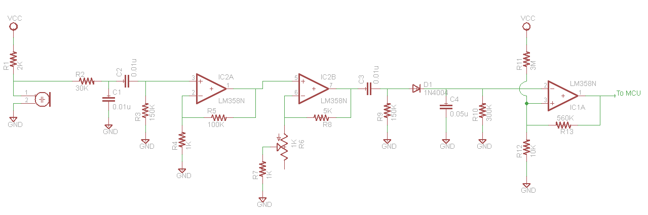
Filter circuit diagram
The signal processing on the microphones was one of the more challenging aspects of the project. The microphone signal went through the following stages:
1. Initial biased microphone
2. Low pass filter with a cutoff at 500Hz
3. High pass filter with a cutoff at 100Hz
4. Non-inverting amplifier with gain of 100
5. Non-inverting amplifier with gain of 2.5-5, tunable with a potentiometer
6. High pass filter with a cutoff at 100Hz
7. Peak detect circuit
8. Schmitt Trigger
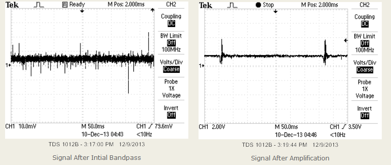
These stages were used to transform a microphone signal into a digital signal for the microcontroller. The microphone is biased with a 2kΩ resistor to a 5V line. This microphone signal is then passed through a low pass and a high pass filter to create a passive bandpass. This bandpass allows signals between 100Hz and 500Hz, which are the primary frequencies of human speech. This filtered signal is passed through a bandpass with a gain of 100 to amplify it to a reasonable range. It is then amplified again, but with much smaller gain. This second gain stage has two purposes. First, it allows us to have a large gain without approaching the bandwidth of the LM358 op-amps. Second, it allows us to tune the final amplification of the system. This is important when trying to keep three microphones systems identical. Since all of our resistors are only accurate within our tolerances, and we are not using extremely high quality op-amps, different circuits with the same design can respond differently, even when given the same microphone signal. We tuned these gain stages with a differential op-amp circuit. A pair of circuits would be connected to the same microphone. The output of the two gain stages was then put through a differential op-amp. By tuning the potentiometers, we were able to get the differential output as close to zero as possible. We then changed the pair of microphones in use to tune the third microphone to be identical to the first two tested.
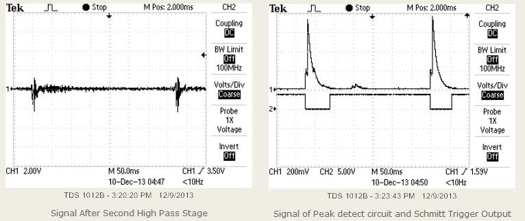
After the gain stage, the signal went through another high pass filter to remove the DC offset. This was followed by a peak detect circuit. This circuit would charge a capacitor when the voltage was high, and discharge through a resistor when the voltage was low. We found that tuning these capacitors and resistors was a challenge. The relationship between size of the capacitor and resistor was the key issue. If the capacitor was comparatively too small the peak detect circuit would discharge too quickly, and would not provide meaningful peaks. If the capacitor was comparatively too large, the peak detect circuit would not rise fast enough.
This rise time became a key issue in testing the Schmitt trigger. The inverting Schmitt trigger was set to trigger low at 100mV and back high at 10mV. In order for this value to be useful, the three circuits need to have extremely similar rise times. All of the timing calculations are based upon the moment that the Schmitt trigger goes low. Since the circuits have slight differences, signals with extremely fast rise times work much better than signals we slower rise times. Because of this behavior, the system responds well to the snapping of fingers, claps, and other sounds that produce impulse-like waveforms.
Issues with Voice Recognition
Our initial plan for this project was to have the device determine the location of a person based on the sound of his or her voice. This is why we began our circuit with a bandpass between 100 and 500Hz. However, as we tested, we discovered that our system responded much more accurately to snapping fingers, or claps, than a person’s voice. This is because the snapping of fingers produces an impulse of sound with an extremely high rise time. However, speech is much less perfect. When a person speaks, the waveform from the peak detect circuit will often produce a slow, smooth peak before a sharper peak. This is caused because of our speech patterns. Impulses in voices are more likely on words with hard first syllables, but even then, we typically ramp up our volume rather than immediately open with a sharp noise. These sounds are difficult to produce even when attempting to speak pointedly for the sake of testing. We ultimately determined that in order to produce voice recognition we would have to make major design changes to the way we process the sounds, and ultimately tuned the circuit to be more accurate for impulses.
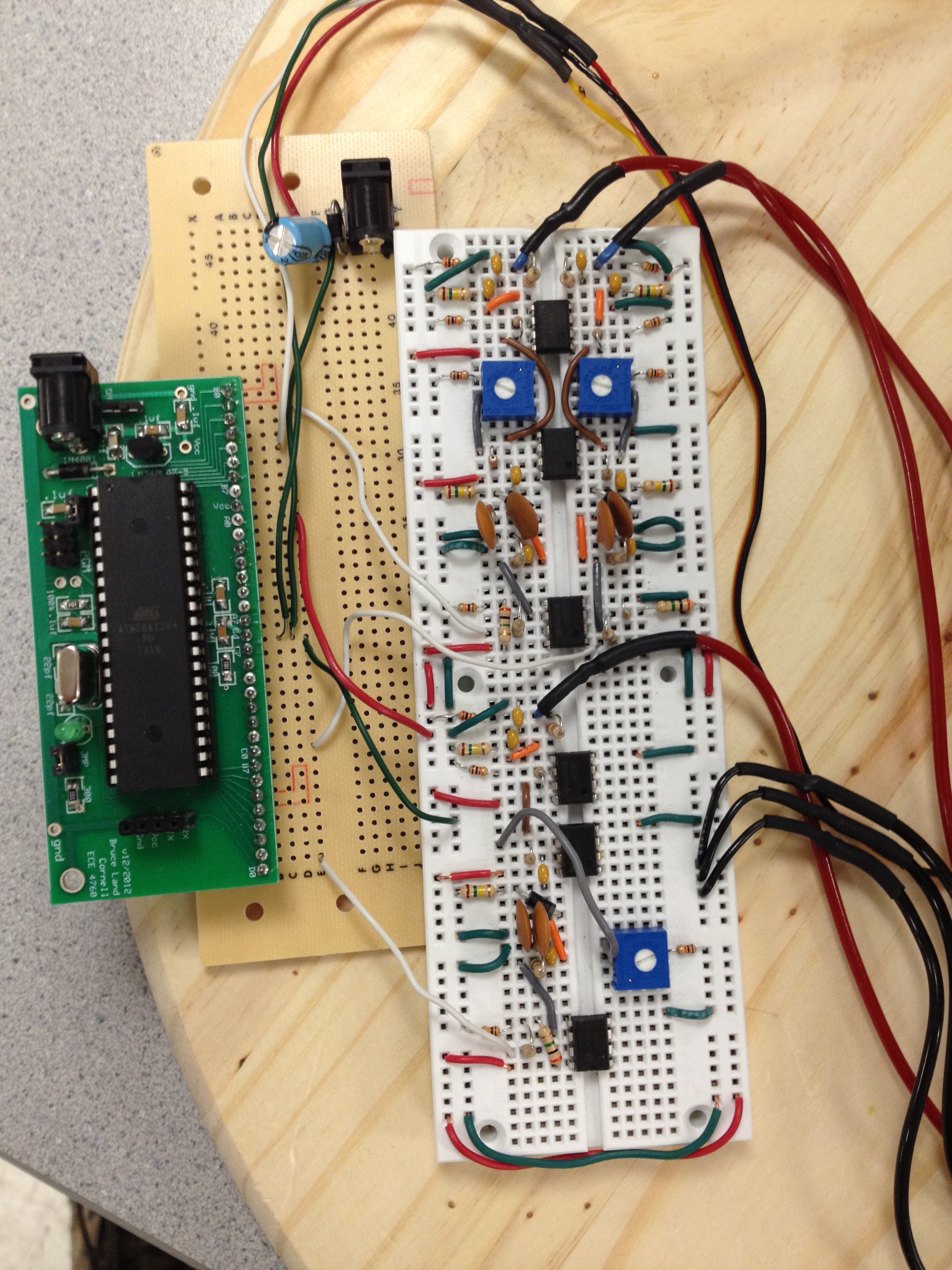
Circuit Placement
Software top
Our software was created using Tiny Real Time (TRT). This was done to make the software easily expandable. The angle calculation occurs entirely in the interrupt service routines and one task, and a second task can be used for any purpose that uses the data found. Our current code points a flag at any location where a noise is located. However, the second task can incorporate any functionality. For instance, our code contains a commented script which will average calculated angles to tune the device and also can discard faulty data. We hope that our code is able to be expanded for real world cases, and the TRT framework will allow us to do this without many edits. The only semaphore that is currently protected in our code is the calculated angle that the sound can be found at.
Servo Control
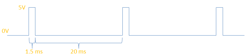
The specific servo we are using is controlled with a standard 5V pulse signal ranging from roughly 500us to 2500us, with roughly 20ms pauses between each pulse. The shortest pulse corresponds to a position of 0 degrees, while the longest pulse corresponds to a position of 180 degrees. The precise timing of the pulse is maintained using interrupts and Timer 0.
Timer 0 is enabled with a 256 clock divider, making the timer overflow every 4.096ms. This gives us enough precision to specify a pulse time between 500us and 2500us. The overflow and compare match interrupts are enabled on timer 0. We also enable pin B.3 to serve as the output of the servo control signal.
The compare match register OCR0A is set to a value between 0 and 255, which corresponds to the time that the pulse is held at 5V, and therefore also directly controls the absolute position of the servo. Pin B.3 is set high, and Timer 0 proceeds to count up until it reaches the value of the compare match register. It then enters the compare match interrupt ISR, where pin B.3 is pulled low again to precisely control the pulse time. In order to delay roughly 20ms before sending the precisely timed pulse again, pin B.3 is set high again only after timer 0 overflows exactly 4 times, resulting in an actual delay of about 16ms. The exact delay time in unimportant in the control of a servo.
Since every servo is slightly different in its mechanical properties, it must be calibrated in order to signal exact positions accurately. To do this, we slowly varied the pulse time and recorded the exact durations which corresponded to 0 degrees, 90 degrees, and 180 degrees. Our calibrations resulted in a range from 535us to 2425us. In order to accurately specify the value of the compare match register given a desired degree between 0 and 180, we use the function servo(degree). It takes the desired degree as an input, divides is by 180 to get a fraction, and multiplies that by the calibrated range of the servo in miliseconds: 2425-535. This value is added to the minimum pulse range (535) to correctly offset it, then multiplied by the timer clock rate (62500Hz), divided by 1000 to account for using the units of milliseconds. Finally a 1 is subtracted to shift the range from 1-256 to the correct range 0-155.
OCR0A= (int)(round( ( (float) (degree * (float) (servo_max - servo_min) / (float) 180.0) + servo_min) * 62.5) -1);
Note: Since our system uses a 360 degree range, the input degree is first divided by 2 to scale it to the 180 degree range of the servo. Our mechanical gear system multiples the servo’s angel by 2, giving us the actual desired 360 degree range.
Example Servo Control Signal
Servo Power
The servo is powered with an external 5V, 5 watt DC power supply in order to isolate it from the Vcc rail of our microcontroller. The servo still shares a common ground with the entire rest of the system. On the power line of the servo, we added a 33uF electrolytic capacitor and a flyback diode from the power line to the ground line. These components help to buffer the current spikes of the servo as it maintains its position. Servo motors generally move using rapid, sharp current spikes which can be taxing on a small DC power supply.
Microphone Interrupts
After going through all the analog circuitry, the output of each microphone circuit is designed to output a logic high signal when there is no sound, and a logic low when that microphone has been “triggered” by a sound. They operate using an active-low signal. The microcontroller has three external interrupts enabled on ports A, B and C using pin 0 of each of those ports. The interrupts are set to trigger on any logic level change. In this setup, we can maintain exactly which microphone has been triggered and simply check if it just changed to a logic low or high inside of each ISR. Timer 2 is used to measure the delay between microphones, and it is setup to run at 250,000Hz, giving an overflow time of 1024us and a precision of 4us. These values were chosen based on the longest possible delay for a sound pulse to travel across the separation distance of the microphones.
The microphone trigger logic is based on a state machine within the three external interrupt ISR’s. The system begins in state 0, indicated by the variable “mic_state”. When the first mic is triggered and changes to a logic low, the system enters state 1 and saves that microphone number as the first element of array mic_order to keep track of the order of triggers. Timer2 is reset to begin counting the time until the next microphone is triggered. When the second mic is triggered a few microseconds later, the system enters state 2 and saves that microphone number as the second element of mic_order. The value of Timer2 is also saved, to record the time delay between the first and second triggers. Finally when the third microphone is triggered, the system enters state 3 and repeats the actions above. The value of Timer2 is saved again, and the 3rd element of mic_order is updated. Now that all 3 microphones have triggered in succession, the vector_update_flag variable is set to 1 to indicate that the system should begin using all the stored values to calculate the exact angle at which the sound originated from.
There are many ways that the system can fail to acquire an ideal sound pulse that triggers all three microphones in succession. This could be due to ambient noise, sounds that are too smooth to trigger promptly, quiet sounds, etc. Therefore, is is important to reset the system back to state 0 any time the measurements are not idea. First, if Timer2 overflows after 1024us then the system resets to state 0. If any microphone reverts to a high state and therefore stops being triggered, the system resets back to state 0. This ensures that all three microphones must start un-triggered, they must all trigger within a 1024us, and they must not stop being triggered until state 3 is reached. Once the vector_update_flag is set to 1, the very first calculation is to check whether the microphone delays were less than the exact maximum value allowed, given the calibrated speed of sound and microphone distances used. If the delay was less than 1024us but greater than this exact maximum value, the angle calculation never begins and the sound pulse is ignored.
Vector Calculation
The vector calculation is based primarily on the velocity of sound in air, the microphone separation distance, the acoustic time delay between any 2 microphones, and a very key assumption that the sound originates from a distance of at least one order of magnitude greater than the microphone separation distance. By making this assumption, we can model the acoustic source at infinity, and assume that the mathematical lines connecting the sound source to each microphone are all parallel. This key assumption eliminates our ability to determine the exact distance to the acoustic source, but it allows us to determine the source vector with very high accuracy using only 2 microphones.
We found that the accuracy of any vector calculation was highly dependent on the proximity to 0 degrees between the 2 chosen microphones. This observed behavior can be justified because the time delay between the 2 microphones is passed through a cosine function. At angles of 0 or 180 degrees, a small change in time causes a large change in the angle calculated. However, at angles closer to 90 degrees, a larger change in time is necessary for a small change in the angle calculated to occur. This is because of the slope of cosine curve at 90 degrees. Because of this fact, we use a dynamic calculation which determines which 2 microphones would place the source closest to 90 degrees. Because of the triangular configuration of the microphones, after picking the optimal microphones, the angle being calculated will never be larger than 30 degrees.
After calculating an angle, we need to determine where the sound originated. We can do this by dividing the circle into 12 sections, each 30 degrees wide.
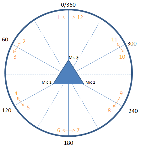
Angle Sections
We first differentiate these sections by checking which two microphones were used to calculate the angle. By knowing which microphones were used, we can narrow the number of possible sections down to the 4 sections which would be closest to 90 for those microphones. This includes two sections of each side of the circle. For instance, in the diagram above, if microphones 1 and 2 were used, we would know the sound came from sections 1, 6, 7, or 12.
We then check the order of the microphones. If the signal from the microphone not used for calculating the angle comes before the other two, we know that the sound came from the side closest to that microphone. If not, we know the sound came from the other side. In our example, if microphone 3 received a sound signal before microphones 1 and 2, we know the sound came from sections 1 or 12.
Finally, we look at the order that the sound reached the calculating microphones. This will indicate which side of the 90 degree line the sound originated. In our example, if microphone 1 received the sound before microphone 2, the sound originated in section 1. Once we know the section that the sound lies in, we add or subtract our calculated angle to the proper offset, and we have an exact angle.
By following these steps we are able to accurately locate a sound at any angle, with minimal calculations.
Additional Code Functionality
As mentioned above, this code is easily expandable because of TRT. Our code currently contains a task (which has been commented out for the prototype) which is capable of greatly increasing the accuracy of the readings. When the task receives a sound vector, it compares it to the current sound vector. If the two sounds were found within 20 degrees of one another, it assumes that the sounds have the same source, and averages the calculated values together to account for any errors in the readings. However, if the new sound is greater than 20 degrees away from the previous sound, the microcontroller saves the new value and waits for a third sound to trigger. If this sound matches the location of the second sound, the microcontroller will assume that the user has a new location and will turn the servo accordingly. However, if this sound does not match the second sound, the microcontroller can safely assume that it has received an incorrect reading, and will not turn the servo. This is useful in cases where it is important that the servo never turns to an incorrect location.
Results top
Speed of execution
Our system executes very accurately in real time. By performing all the state calculations and data acquisition in the ISR’s, we ensure that the critical time measurements and acquisition takes the highest priority in the system in order to ensure the highest accuracy in the software calculations. TRT allows us to perform all the time consuming mathematical analysis and vector calculations outside of the ISR’s when the system is not acquiring critical data, and we have found that these calculations still occur fast enough that there is absolutely no noticeable delay in between a sound impulse and the servo pointing to the source. We have noticed that the servo can incur some jitter while it is holding a set position, but our analysis has concluded that the source of the jitter is within the servo itself, and not from our control signal or power rail.
Accuracy
Our system is extremely accurate at marking sharp impulse sounds like a finger snap, click, or clap. We found that this system is not effective for detecting smoother sounds like human speech, music, or ambient noises. Because the detection is based on an analog impulse trigger, these smoother sounds do not trigger the microphones accurately enough to determine their source vector. The mathematical calculations we use to calculate angles has precision of 0.65 degrees, and the servo control code that we have implemented has precision of 3.0 degrees. Using these precision limitations while also testing our entire system for analog accuracy, we estimate that we can identify a sound impulse to within 5 degrees of accuracy. Finally, we also found that our system must have its ground connected to Earth Ground of the building in which it operates to function at all. Since the system is heavily analog based, it is very susceptible to ambient electrical noise and it must be properly grounded to function.
Safety
For our project, the main safety concern was the servo. If the servo is sent a signal driving it outside of its operating range it could draw excessive amounts of current, in excess of 1A. This could cause safety concerns for users due to short circuits. In order to prevent this, we added limit checking into our code which does not allow the servo to go beyond its safe bounds, even if a bad angle calculation were to somehow command it to. As an added measure of safety, the servo has its own isolated power supply, separate from the microcontroller, so that the microcontroller does not experience an excessive load and fail. All the wires on the system are neatly tied to the frame or glued down to the base to eliminate the possibility of snagging them on a user, or on the servo gears. Our analog hardware does not have any safety concerns because all of the signals are very low power.
Interference
Our project does not output any data expect a signal line controlling the servo, so we cannot interfere with any other projects. However, our project is easily interfered with. Not only can ambient noise in the room cause issues, but even electrical noise can cause our system to fail. It is because of this interference that our system must be grounded to earth ground at all times when operating or it will not be able to successful function.
Conclusion top
The most important and innovative part of our project is the design of our dynamic angle calculation algorithm. By assuming the sound pulse is at an infinite distance we are able to determine an angle using only two microphones, and by dynamically changing which microphones are used we are able to obtain an impressive amount of accuracy from a single sound pulse. The core use of interrupts allows us to run the system in real time for timing data acquisition, and the use of TRT allows us to run multiple virtual tasks whenever the microcontroller is not performing data acquisition. This allows for high precision, large computations to take place without interfering with any of the sound timing. We believe that these design choices represent the true innovation in this project, and they open up the possibility of using this system as part of a larger system which requires sound targeting.
Our Expectations
Our original goal for this project was to design a system that could detect human speech, and identify the source of the sound. We envisioned it being used to aim a camera during events such as multi-person web conferences. As our design evolved, we found it infeasible to detect voices using our peak detection circuit, and so we began focusing on sharp impulse sounds like a snap or clap. Once we saw the potential accuracy achievable with these sounds, our main goal shifted from a specific use in a conference room to a challenge of how accurately we could identify an impulse sound. We added our third microphone and discovered the benefits of dynamically calculating the sound angle, and ultimately achieved accuracy that exceeded our expectations.
Future Improvements
With greater resources, we believe that our system could be designed using signal pattern matching rather than simple binary peak detection. This would require the use of a very fast ADC, which would send the signal amplitude values to the microcontroller. The microcontroller would have to maintain arrays of signal amplitudes for each microphone, and match the signal peaks within those three arrays. When the signal peaks are matched, it would be possible to compute the delay between the peaks on all three microphones, and then use that delay data to compute the angle exactly as in our existing system. This major change would not target the computation for the sound angle, but rather the delay acquisition and we believe this is what would be required to identify the source of many sound types, including human speech, because it would not limit the system to detecting a single sound impulse.
Standards
We used UART serial communication protocol at 9600 baud rate in order to debug our system. By connecting the UART serial output of the microcontroller to a PC’s serial port, we were able to send debug statements to the PC. The UART communication was not used at all in our final system, because there was no need for any system communication once everything was working.
We used a standard servo control PWM signal to control the absolute positioning of the servo motor. Our servo motor accepted 5V pulses from roughly 500us to 2500us in duration, with pauses of roughly 20ms between each pulse. These values were calibrated exactly for the specific servo in our system.
Calibration
The following lists the exact calibration values used in our software.
Minimum Servo Pulse (0 Degrees) = 0.535 ms
Maximum Servo Pulse (180 Degrees) = 2.425 ms
Speed of Sound = 340.29 m/sec
Microphone Separation Distance = 14.0 cm
Intellectual property
Our software implementation was based on the “TinyRealTime” kernel written by Dan Henriksson and Anton Cervin in 2004. We used this kernel to implement concurrent processes on our ATmega1284 microcontroller. Their source files were used with permission given to Cornell University. All other code was written independently by us. The mechanical and electrical hardware setups were designed and integrated completely independently by us also.
We did not sign any non-disclosure forms, as all of our parts were acquired through our own purchasing or available laboratory parts. We did not use anyone else’s designs or published work to base our design on. All the ideas, design and development took place in our lab with the aid of our TA and Professor Land. However, once our project was completed, we did investigate patents in the realm of our acoustic localization design and just as we suspected, there were many patents in this area. Most of the patented designs and algorithms were far more advanced than our system, and there are two specific patents worth noting: (US4581758 A) In 1983 Cecil H. Coker and David R. Fischell of Bell Laboratories first invented a system very similar to our working project. They seem to have been the first ones to patent the process of identifying a sharp sound source direction by using a pair of microphones, and timing their pulse arrival times. Second, (US5778082 A) in 1996 Peter L. Chu and Hong Wang of Picturetel Corporation patented a method and apparatus which resembles the future work that we wanted to pursue with our project, which compares sample sequences from different microphones to determine the timing offset between two signals. This timing delay is then used to calculate the source direction as we did in our project. Because their system uses signal matching, it was designed specifically for speech detection and its applications were cited as videoconferencing.
Because of these established patents, there are currently very little patent opportunities for our project. However, we would still like to pursue publication opportunities with sources such as IEEE in order to share our work. We believe it could still be very useful as an integral part of future systems, considering it was designed and built with so little funding and development time when comparison to industry standards.
Legal Considerations
Our project has no known legal restrictions. It is a basic sound sensor that does not transmit any data or save any data about the user. Also, all components are consumer components, which were purchased online.
Code of Ethics
Our project strictly adheres to the IEEE Code of Ethics in all aspects. The two main points that directly relate to our project are point 3 (”to be honest and realistic in stating claims or estimates based on available data”) and point 7 (“to seek, accept, and offer honest criticism of technical work, to acknowledge and correct errors, and to credit properly the contributions of others”). First, we tested our system to the absolute best of our capabilities and reported our performance and accuracy honestly. We were realistic with our system’s capabilities and shortcomings, and honestly reported them in our documentation for potential users. Second, we proposed our project idea to the TA’s of this class and to Professor Bruce Land for full disclosure and criticism. We worked closely with Professor Land to develop our project further and to seek guidance, and we kept our TA up to date as our project evolved due to our testing and development. As our design process progressed we were able to identify mistakes in both our hardware and software with the help of the TA’s and Professor Land, and they were able to assist us in correcting those mistakes in the most efficient manner. Finally, we exhibited an earnest effort to give full credit to any ideas and designed that we referenced, as well as any code that we utilized in our project. The latter is extremely important in our project due to our use of the TRT kernel as the backbone of our software implementation.
Appendices top
A. Schematic
B. Parts List and Costs
| Component | Vendor | Part # | Unit Cost | Quantity | Net Cost |
|---|---|---|---|---|---|
| Solderless Bread Board | Lab Supply | n/a | $6.00 | 1 | $6.00 |
| Solder Board | Lab Supply | n/a | $2.50 | 1 | $2.50 |
| DC Power Supply | Lab Supply | n/a | $5.00 | 2 | $10.00 |
| Mega1284 | Lab Supply | n/a | $5.00 | 1 | $5.00 |
| Custom PCB Board | Lab Supply | n/a | $4.00 | 1 | $4.00 |
| Header Pins | Lab Supply | n/a | $0.05 | 48 | $2.40 |
| 1K resistor | Lab Supply | n/a | $ - |
6 | $ - |
| 2K resistor | Lab Supply | n/a | $ - |
3 | $ - |
| 5K resistor | Lab Supply | n/a | $ - |
3 | $ - |
| 10K resistor | Lab Supply | n/a | $ - |
3 | $ - |
| 30K resistor | Lab Supply | n/a | $ - |
3 | $ - |
| 100K resistor | Lab Supply | n/a | $ - |
3 | $ - |
| 150K resistor | Lab Supply | n/a | $ - |
6 | $ - |
| 300K resistor | Lab Supply | n/a | $ - |
3 | $ - |
| 560K resistor | Lab Supply | n/a | $ - |
3 | $ - |
| 3M resistor | Lab Supply | n/a | $ - |
3 | $ - |
| 1N4004 Diode | Lab Supply | n/a | $ - |
6 | $ - |
| 10nF capacitor | Lab Supply | n/a | $ - |
12 | $ - |
| 20nF capacitor | Lab Supply | n/a | $ - |
6 | $ - |
| 33uF capacitor | Lab Supply | n/a | $ - |
1 | $ - |
| 1K potentiometer | Lab Supply | n/a | $ - |
3 | $ - |
| LM358 Op Amp | Lab Supply | n/a | $ - |
6 | $ - |
| Wire | Lab Supply | n/a | $ - |
n/a | $ - |
| 1/4" Bearing Mount | ServoCity | 535110 | $5.99 | 2 | $11.98 |
| 1" Aluminum Standoffs | ServoCity | 534-3489 | $0.70 | 4 | $2.80 |
| 1/4" x 3" Shaft | ServoCity | 634162 | $1.19 | 1 | $1.19 |
| 64 Tooth Servo Gear | ServoCity | RSA32-2HS-64 | $6.84 | 1 | $6.84 |
| 32 Tooth Bore Gear | ServoCity | SPBD32-34-32 | $2.36 | 1 | $2.36 |
| Machine Screws | ServoCity | 90272A144 | $0.05 | 8 | $0.40 |
| FET Micorphones | DigiKey | 102-1728-ND | $1.83 | 3 | $5.49 |
| Hitec Servo | Sparkfun | HS-425BB | $12.95 | 1 | $12.95 |
| 1x2 Pine Board | Home Depot | n/a | $3.58 | 1 | $3.58 |
| L-Bracket 4-Pack | Home Depot | n/a | $2.27 | 1 | $2.27 |
| Zinc Wood Screws Pack | Home Depot | n/a | $1.18 | 1 | $1.18 |
| Round Pine Base | Home Depot | n/a | $4.88 | 1 | $4.88 |
| TOTAL: | $85.82 |
C. Source Code
main.c
trtkernel_1284.c
trtSettings.h
trtUart.c
trtUart.h
D. Division of Labor
During this project most of our work was done together, especially the design work, debugging and testing, and the interfacing of all the parts of our system.
More specifically, Adam led the implementation of the analog circuit construction and tuning, the adaptive microphone selection algorithm, the website design, and the example averaging algorithm.
Michael led the implementation of the physical structural design and wiring, the servo control and hardware linkages, the microphone interrupt state machine, and the algorithms for single angle calculations.
References top
Datasheets
References
Vendors
Acknowledgements top
We would like to thank Professor Bruce Land and the TA’s of ECE 4760, especially Cameron Glass, for all their help and dedication to making this project possible. Bruce Land has been a true mentor for us and gave us the chance to explore the full potential of our engineering knowledge. We would also like to thank Cameron Glass, Omeo Quddus, and Roland Krieger for their website template which we used to create this page.