Never get lost on a run again with a runners’ GPS!
Runners who have moved to a new city may get lost trying to remember the route they carefully planned at home. Instead of stopping the run to pull out a phone, wait for the map to load, find where you are, and determine where you need to go, why not carry something that will automatically tell you where to go without interfering with your run? The GPS Running Watch is a personal GPS guidance device to help runners follow unfamiliar routes using an LCD display and haptic feedback. It guides the user along a path between preselected latitude/longitude waypoints by vibrating a small motor to indicate whether the waypoint is straight ahead, to the left, or to the right. You can stop worrying about losing your way home, and get back to enjoying your run.
High Level Design top
Rationale
The idea for this project came from a brainstorm of different applications for GPS. GPS receivers are everywhere in the modern world, and are small and simple enough to use with a microcontroller to a reasonable degree of accuracy. There are many websites and smartphone apps that can help runners find and create routes but what they don't do is guide runners while running those routes. There is no feedback to indicate where the next turn is, or in which direction to turn. A smartphone app could interrupt music that may be playing to indicate when and how to turn, but that would remove the user from the general peace of the run and force the user to think about the next turn. All those interruptions could get very irritating. A better solution would be to indicate the next turn through haptic feedback. A vibration on a user's left arm would naturally indicate a turn to the left, and a vibration on the right arm would naturally indicate a turn to the right. We use this method of feedback to seamlessly guide the user along a route without interrupting the run.
GPS Running Watch
Logical Structure
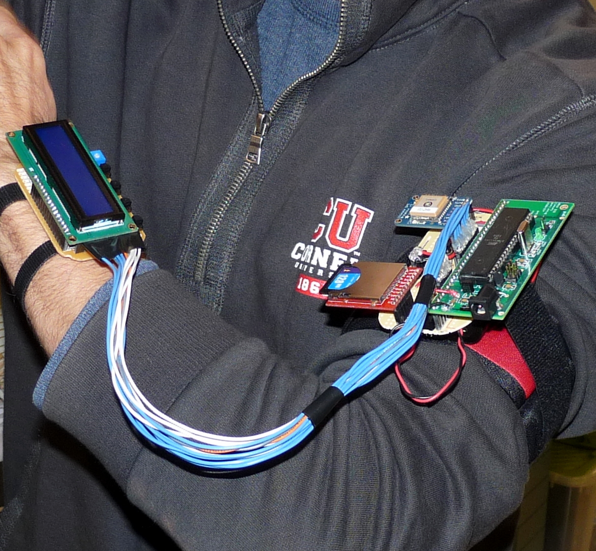
Our device provides basic route navigation guidance and waypoint logging using GPS. An ATMega1284 microcontroller unit (MCU) receives GPS data from a receiver module, and user selections from four pushbuttons. The pushbuttons allow the user to move through different menus, make selections, and return to previous menus or exit the current function. During route navigation, the MCU displays route information on an LCD display and gives turn indications through two vibration motors. The MCU retrieves waypoints from routes saved in text files on an SD card. For waypoint logging, the MCU only uses the LCD display and not the vibration motors. The MCU saves waypoints to a text file on the SD card.

High-level hardware block diagram
The GPS module sends NMEA strings containing certain GPS data over a serial communication line. The MCU can control the speed of the data connection, the update rate, and the type of information that the module provides. We chose a 9600 baud rate with a 1 Hz update rate for new information, which is fast enough for our application. The GPS module provides the GPGGA and GPRMC NMEA sentences to the MCU. These sentences give the receiver’s latitude, longitude, altitude, speed, and bearing, the current UTC time, and the state of the GPS satellite fix. We use all this information for the route navigation function, and all except the speed and bearing for the waypoint logging function.
The SD card stores routes as a list of comma-separated latitude/longitude waypoints in text files. The first line in these text files is a header with no useful information to the MCU. Each subsequent line contains a waypoint starting with a ‘T’ followed by a latitude, a longitude, a waypoint name (not necessary), and a description (also not necessary). As mentioned before, each of these five values are separated by commas to make it easy for the MCU to parse them. The MCU only extracts the latitude and longitude from each line and stores them in two arrays: one for latitudes, and one for longitudes. It moves through these arrays as the user runs the route. In the waypoint logging function, the MCU stores waypoints in the exact same format. We use this format because it is used by the website we use to convert between text files and Google Earth KML files (www.gpsvisualizer.com).
The GPS Visualizer website makes it much easier to use Google Earth to create and view routes. While a user could create a text file with our format by entering each latitude and longitude, a less tedious solution, which we recommend, is the following:
- Create a path in Google Earth
- Save the path as a KMZ file
- Upload the KMZ file to the GPS Visualizer website and output a comma-separated text file
- Copy the output to a text file and save this text file to the SD card
A user can view his saved waypoints from the waypoint logging function in a similar manner:
- Upload the text file to the GPS Visualizer website and output a KML file
- Use Google Earth to open the KML file
- The path should appear as a series of red lines as shown below

Example path (red) created by the waypoint logging function shown in Google Earth. Yellow pins show actual position for each point
The LCD displays certain information to the user depending on the current function. In route navigation, it displays the current waypoint number, the elapsed time since the start of the run, the distance in meters to the next waypoint, and the runner’s current speed in kilometers per hour. When the user completes the run, it displays the total completed distance of the run and the total time. During waypoint logging, the LCD displays the current local time, and the user’s latitude, longitude, and altitude. Outside of these two functions, it displays different menus.
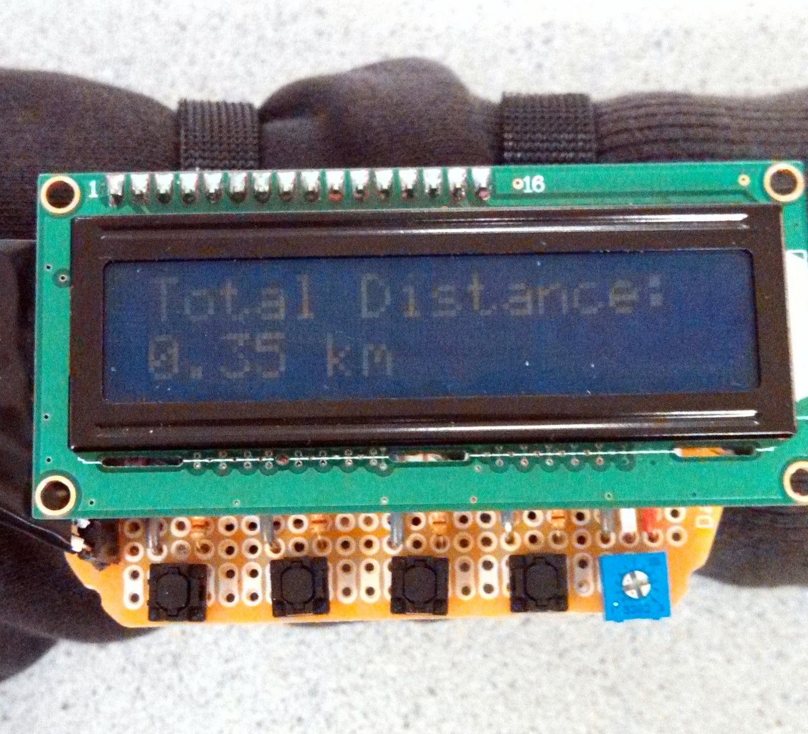
Figure 3. LCD displaying the accumulated distance statistic.
Hardware and Software Tradeoffs
Hardware
There were four major hardware tradeoffs in this project: wired vs. wireless communication, board size, battery size, and LCD type. Since our hardware is split into three groups situated on three different parts of the user's body, there has to be some way for all the hardware to communicate. The simplest solution is to run wires between the different groups. Wires and pin headers are cheap, relatively compact, and do not require additional software. On the other hand, wires can restrict the user's movement, which is not ideal for runners. Another solution is to use short-range wireless RF communication, such as Bluetooth. Bluetooth would not restrict the user's movement. However, it can be difficult to use with microcontrollers, requires more hardware and software to run, adds more weight than wires, and is significantly more expensive than wires. Considering our time and budget constraints, we chose to use wires even though wires impede the user experience to some degree.
The main board in our project is much bigger than it could be because we are using a PDIP-package ATMega1284. If we had designed our own printed circuit board (PCB) and used a TQFP-package ATMega1284, the main microcontroller board could be half its current size (just the size of the green PCB in the picture). A smaller board would be better for the user who has to wear it on his arm, and could better incorporate the battery pack. Although a PCB has benefits, it is also more expensive, more time-consuming in design work and fabrication, and harder to fix if we made an error in the design. Since time and budget are our two main constraints and we already had a microcontroller carrier board from the lab, we decided to use the carrier board and a protoboard to connect the other hardware.
Our choice to use 3 AA batteries to power the project was a little unintended. Since one of us already had a battery holder for 3 AA batteries, it was a quick and easy solution for powering the hardware for outside tests. The voltage from the AA batteries starts around 4.7V and drops to around 4.5V over time, which is still acceptable for 5V devices, and doesn't require a voltage regulator. The ATMega1284 will run at 16 MHz with at least 4.5V, so the AA batteries work. A better solution may have been to use a two-cell lithium battery with a small voltage regulator. A lithium battery would have been much smaller and lighter than the AA batteries, and could have been recharged with an on-board recharging circuit. Since the AA batteries worked just fine and were readily available, we forgot to consider lithium batteries any further. In retrospect, lithium batteries would have been better for weight and size, but they have more safety problems and require more on-board hardware for charging or an external charger. A compromise on size and weight may have been to use AAA batteries instead of AA batteries, but we did not consider this change worthwhile as we already had a AA battery holder.
The last hardware tradeoff was the LCD. The LCD is the main visual interface, and the only user interface during the waypoint-logging function. A larger character LCD would allow us to display more information to the user, but would also be bulkier and heavier. Since the LCD is sitting on the user's forearm, the size and weight should be as small as possible to reduce fatigue. A 16x2 character LCD, like the one we use, is a good tradeoff for these criteria. However, a graphic LCD might be able to display more information, albeit in a smaller font, with a smaller board size. We chose to not use this type of display because it is often more expensive, requires more software, and would display information in a smaller size, which would not be ideal for some users.
Software
The main software tradeoff was whether or not a real-time kernel would be used. A real-time kernel has the advantage of easy timing of multiple tasks that need to be run simultaneously. A custom scheduler on the other hand allows for more precise timing of time-sensitive tasks and the ability to ensure the MCU is never overloaded. Because the project does not require many simultaneous processes, a real-time kernel is not required. Additionally, two tasks, including the clock for the SD card, and the GPS update signal needed to be called at certain intervals. Therefore, a custom scheduler was used that was run off of TIMER0 with a 1ms time-base.
Background Math
One part of our design is to calculate the distance remaining between the user and the next waypoint, which involves finding the difference between two latitude/longitude points on a sphere. An exact calculation of this distance requires the haversine formula, which is shown in equation 1. $\varphi$ is latitude, and $\lambda$ is longitude, and all angles are in radians.
$a = \sin^2(\frac{\varphi_2-\varphi_1}{2})+\cos(\varphi_1)\cos(\varphi_2)\sin^2(\frac{\lambda_2-\lambda_1}{2})$ (1)
Equation 2 uses the haversine result above to find the distance on the Earth's surface. $R_E$ is the Earth's radius approximated to be a constant 6371000 meters.
$d = 2R_E*atan2(\sqrt{a},\sqrt{1-a})$ (2)
Computing these two equations on a computer is trivial, but it is not trivial on an 8-bit microcontroller such as the ATMega1284. It involves 7 trig functions, 2 square roots, and 6 multiplications of double-type variables (to be reasonably accurate). This amount of computation takes a long time. To decrease computation time, the distance can be approximated using en equirectangular projection. An equirectangular projection is a way to map the Earth onto a 2-D surface in which the lines of latitude and longitude are straight with equal spacing. This projection greatly deforms Earth's actual surface, but gives a reasonable approximation for the distance between two points as long as those points are closer than about 100 km and not near the poles. Since this project deals with waypoints that are no more than a couple kilometers apart, and there are very few, if any, people running near the poles, the equirectangular projection approximation works well. In our testing, it gave exactly the same integer answer as the haversine method, at least to a 200 meter distance. The formula is shown in equation 3.
$d = R_E\sqrt{(\lambda_2-\lambda_1)^2*\cos^2(\frac{\varphi_2+\varphi_1}{2})+(\varphi_2-\varphi_1)^2}$ (3)
This equation only requires one trig function, one square root, and three multiplications; a big increase in performance for no loss in accuracy (for our application).
The other major calculation in our project is the bearing from one latitude/longitude point to another. As with the haversine formula, it requires a lot of trig functions. Unlike the haversine formula, it is only applicable within a certain distance along the great circle path since the bearing changes. However, since our project only deals with the bearing between points that are at most a couple kilometers apart, the change in bearing over distance is not a concern. The formula for the bearing calculation in radians is shown in equation 4.
$b = atan2(\sin(\lambda_2-\lambda_1)\cos(\varphi_2), \cos(\varphi_1)\sin(\varphi_2)-\sin(\varphi_1)\cos(\varphi_2)\cos(\lambda_2-\lambda_1))$ (4)
This equation requires 8 trig functions and 4 multiplications, making it very slow. We tried an approximation but it did not give correct values. Hhowever, equation 4 was fast enough in testing, so we kept it.
Standards
Three commonly used standards were followed in this project. The first is the SD card interface. It uses a SPI connection, so the hardware and software needed to communicate with the card over this bus. Additionally, the SD card uses the FAT data format. SPI or Serial Peripheral Interface is a four pin connection. There is a clock pin which synchronizes the logic between the master and the slave, a master out slave in pin (MOSI), a master in slave out pin (MISO), and a chip select pin. Chip select is used to signal that a particular peripheral is being accessed via the master. Data can then flow across the MISO and MOSI pins simultaneously. Fortunately, communication with an SD card is fairly simple thanks to a library created by “ChaN”. His FatFs module was “ported” to the ATMega644P MCU, which is somewhat compatible with the ATMega1284, in several earlier 4760 projects, most recently the TrckrX Onboard-data-logger. The pins for SPI were simply defined in the FatFs library and the code takes care of the rest.
The second standard is the National Marine Electronics Association (NMEA) protocol for GPS serial communication. In this standard, data is sent over an ASCII serial connection such as UART at a constant rate chosen by the developer. Each cycle, a “sentence” is sent from the “talker” (the GPS module) to the “listener” (the MCU). The sentence always begins with a dollar sign “$” and is then followed by two characters to identify the broadcaster, three characters to determine the type of message, then a series of comma-delimited data. Following the data is the “*” character and a checksum followed by a carriage return and line feed. In the case of GPS data, the data section can contain information such as, latitude, longitude, heading, speed, and current time.
The final standard is the Hitachi HD4470 LCD controller interface. The HD4470 is commonly used to drive a variety of ASCII LCD displays. The interface simply consists of a command/data select pin, a read/write pin and 4 or 8 data pins. Again, the LCD library used in earlier projects was very useful in making the LCD interface easy to use.
Intellectual Property
We did not find any relevant copyrights or trademarks for products similar to ours. We did find research from the Intelligent Systems Lab at the University of Amsterdam for a vibrating belt for cyclists. This belt performs a similar navigation function to our project but strictly for cyclists. It also uses different hardware, such as an Android phone and Arduino Mega microcontroller to interface with the vibration motors. We did not find this research until after we had arrived at the idea for our project, so it did not provide inspiration or motivation for us.
We also found a patent for a haptic feedback navigation device for automobile steering wheels. This patent (U.S. 8,554,410) covers a steering wheel device that connects to a car-based GPS navigation unit and vibrates different parts of the steering wheel to indication directions to waypoints. It only covers using haptic feedback in a steering wheel with a connection to a car-based GPS navigation unit, so it does not apply to our project.
Hardware top
Hardware Overview
Most of the hardware for our device is "plug and play" with the ATMega1284 microcontroller. The GPS module and SD card connect directly to VCC (+4.5V), GND, and certain I/O ports. The pushbuttons and LCD also connect to various I/O ports in series with resistors to limit current flow and protect the MCU ports. Only the two vibration motors do not directly connect to I/O ports, since they can draw up to 100mA at 5V and the MCU only supports up to 20mA on a port pin. Instead, the MCU indirectly turns the motors on and off using a simple driving circuit.
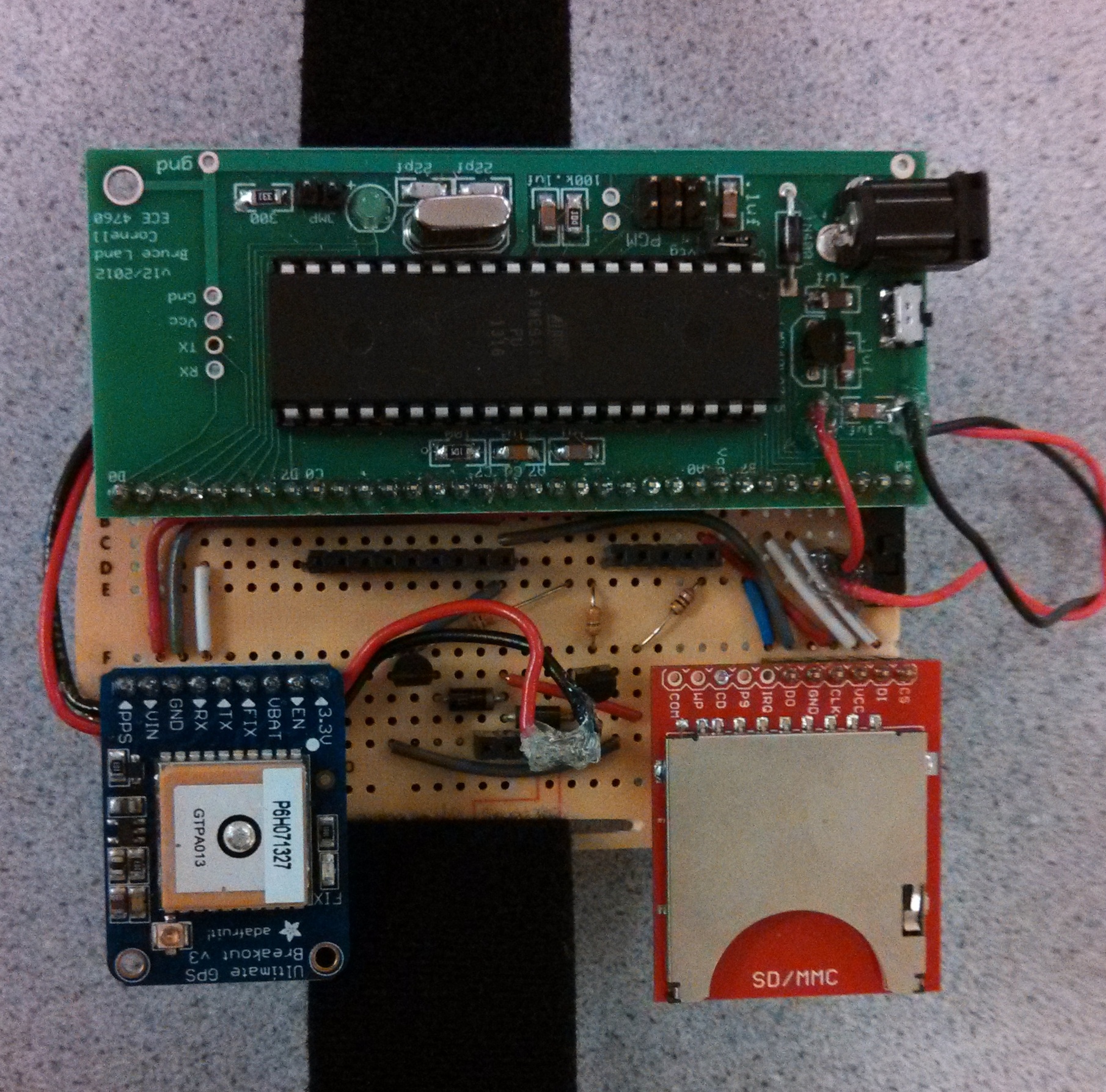
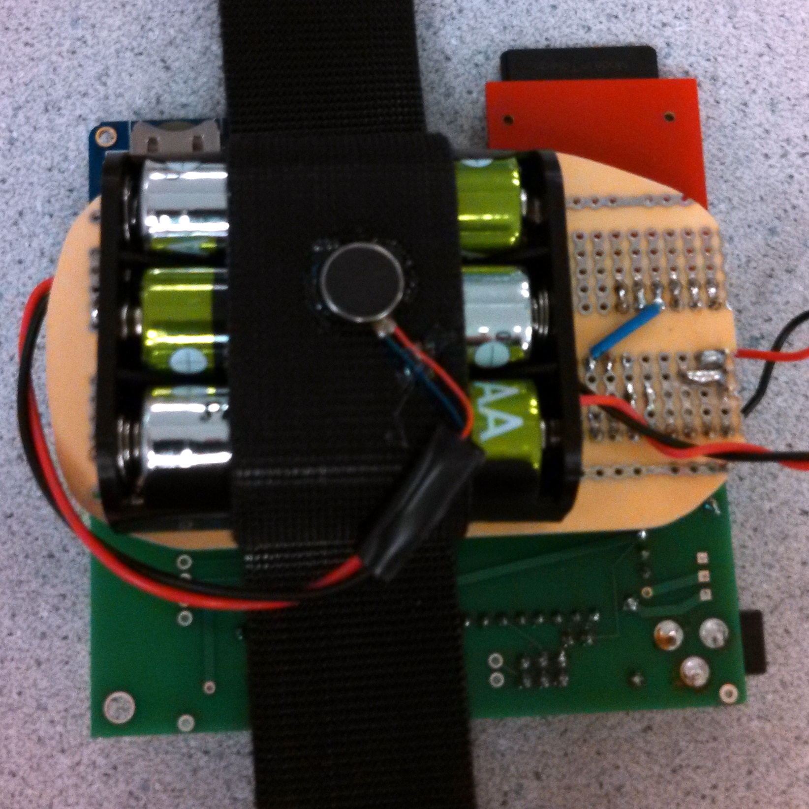
Main board with MCU, GPS, and SD card
We used the ATMega1284 MCU because it is the MCU that we used in the ECE4760 course, so we were familiar with it and its specific capabilities. The carrier board for the MCU has pin headers for all the port pins, a pin header for ISP, and a simple 5V voltage regulator. This board was designed for this course, and the designs can be found here. Although the board is big and bulky, especially for a wearable device, it saved us the cost, time, and possible frustration of designing and ordering a custom PCB. Since our project uses 3 AA batteries for power, we bypassed the voltage regulator and soldered the battery pack wires directly to holes for GND and VCC. However, this direct connection made turning the device on and off during testing a bit annoying because it meant pulling a battery out or putting it back in each time. To fix this, we added a small SPDT switch that connects VCC on the carrier board to the positive battery lead for on or leaves VCC floating for off.
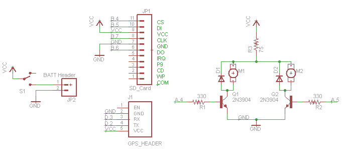
Schematic for the main board
The GPS module we use is the Adafruit Ultimate GPS Breakout v3. It can run on 5V with a 20mA current draw, and outputs NMEA 0183 standard data strings at 1, 5, or 10 Hz. Since it outputs serial data, we connected the receive (RX) and transmit (TX) lines to the UART1 transmit (D.3) and receive (D.2) lines on the MCU. It starts sending data to the MCU immediately after power-on, although the data is not meaningful until the receiver gets a position fix from the GPS satellites. In our tests, the cold-start (time until a position fix) was usually less than two minutes. If we had used the optional coin cell battery, which delivers minimal power to save ephemeris data (information about GPS satellites used in navigation), then the time to fix would have been around 30 seconds.
We scavenged our SD card and SD card holder from the 4760 lab. The SD card is a simple 128MB card with a FAT16 filesystem to store text files. A microSD card would have been better for this project since it's smaller. We originally intended to use a microSD card, but since the lab already had a free SD card and card holder, we chose to use those instead. The card holder is an earlier version of Sparkfun's SD card breakout board found here. The MCU communicates with the SD card over SPI, so we connected the data out, data in, clock, and chip select lines to the MCU's port B.6, B.5, B.7, and B.4 respectively. We tried to use the chip detect pin on the breakout board, but could not make it work reliably.
Our project uses two small vibration motors from Adafruit. To control these motors, we created two separate driver circuits from BJTs and diodes. The BJT (2N3904) acts as a switch to turn a motor on when the base connection receives a high input. The emitter is tied to GND, and the collector is tied to the negative terminal of the motor and the anode of a diode (1N4001). The positive terminal of the motor and the cathode of the diode connect to a 75-ohm resistor to VCC. The diode helps to remove harmful spikes from back-EMF voltages when the motor turns off, while the resistor limits the motor current to around 30mA. Since the motors run straight from the battery pack and not through the 100mA voltage regulator, the current-limiting resistor was not necessary, but it does lower the power consumption and increase battery life. Even at one-third the current, it is possible to feel the motor vibration through three layers of clothing. As with the LCD and pushbuttons, there is a 330-ohm current-limiting resistor between the base of the BJT and the MCU port pin. Port A.5 controls the right motor, and port A.4 controls the left motor.

Locations of left and right vibration motors
We created a carrier board to hold the MCU, GPS module, SD card, motor control circuits, and lots of pin headers. We used pin headers to attach the MCU, GPS module, and SD card so that we could easily remove them. There are also pin headers to attach the cable to the LCD carrier board, the two motors, and the VCC line from the MCU to the power switch. This perfboard has connections like a standard breadboard, which made the wiring and soldering a little simpler. It was orginally 6 inches long, but we trimmed it to be as small as possible, meaning the length of the MCU carrier board. To attach this board to the user's arm, we cut two slots for a strip of Velcro that runs underneath the board. This Velcro strip also holds the battery pack in place. The left vibration motor is epoxied to the bottom of the Velcro strip. The right motor is similarly epoxied to a separate strip of Velcro with the connecting wire strung behind the user's back.
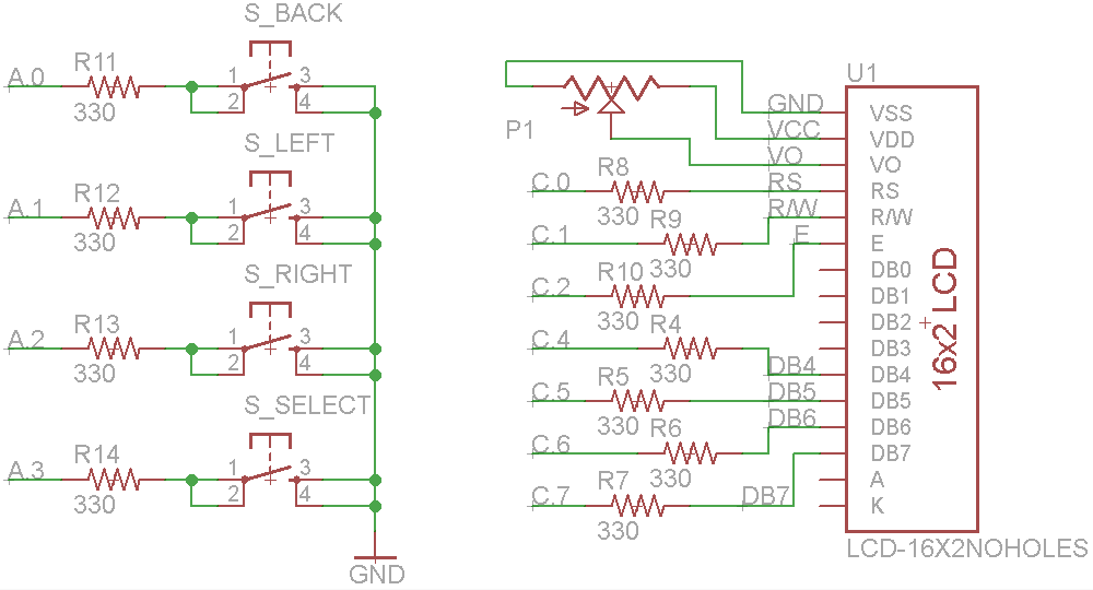
Schematic for the LCD and pushbutton carrier board
We created another carrier board to house an LCD, four pushbuttons, and a potentiometer. This board also contains 330-ohm resistors to limit current between the MCU port pins and each of the pushbuttons and the LCD data and command lines. A pin header on the end connects to the cable that runs from this carrier board to the main carrier board. This cable consists of 7 data/command wires for the LCD, 4 data wires for the pushbuttons, VCC, and GND. The LCD is a simple 16x2 character LCD, which we connected to the port C pins on the MCU as shown here. The potentiometer adjusts the contrast of the LCD. The four pushbuttons are connected between ground and port A.0, A.1, A.2, and A.3. These four port A pins are internally pulled high so pushing the button forces the input low. The carrier board attaches to the user's wrist with two thin Velcro strips that run through slots we cut in the perfboard.
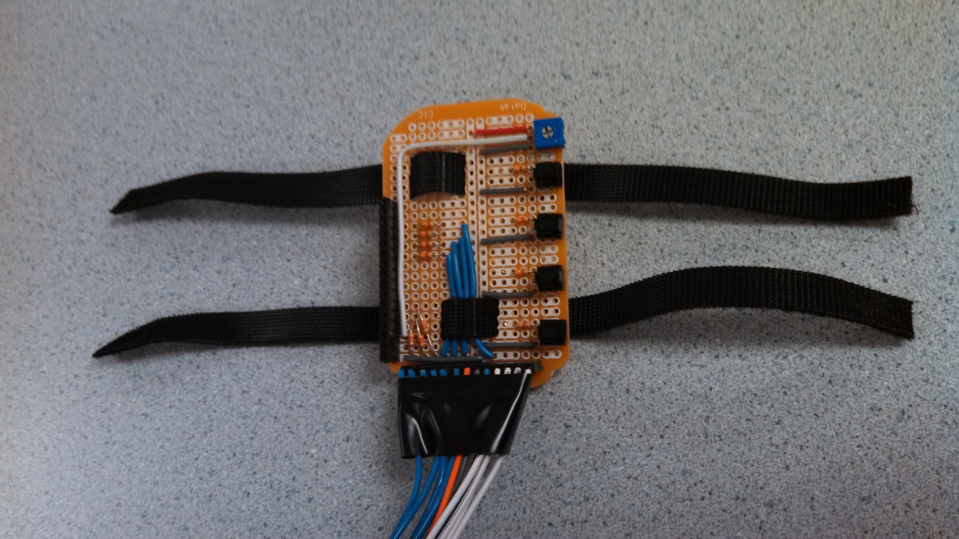
LCD and pushbutton carrier board
Software top
Overall Design
A key feature of the code designed for this project is its modularity. Each of the individual components work fairly independently and could potentially function on their own. Writing the code this way was one of of the main challenges in the software design process, but ultimately led to a quicker integration process of the separately coded modules. For example, the SD card code uses the FatFs library, which has several built-in functions for file-system manipulation. On top of the library, students in previous projects added some new functions at a slightly higher level than the library code itself. These higher level interfaces can be used in the application code to make tasks, such as creating a new file and writing to it or acquiring a directory, much simpler.
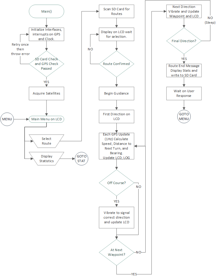
Navigation software block diagram
In the end, the software was divided up into nine individual modules. Four of these were pre-written libraries used for communication with the peripherals. These were FatFs, lcd_lib, uart and uart1. The other five modules are higher level code which utilize the functions within the four low-level libraries as well as the standard AVR and C libraries.
The “buttons” module is a generic state machine used to debounce single button presses on pins A.0-A.3. This module can be easily adapted to debounce any pins on the device by switching the port and/or pin numbers. Any code including buttons.h can then use the debounce() function and associated “butnum” and “button_flag” to debounce a single button press in the user’s desired order of priority. The “gps” module contains the NMEA sentence acquisition and processing code. This code can also function independently as a GPS data handler. As previously mentioned, the “sd” module contains higher level functions for easy use of the FatFs library. It provides several useful functions that can be used independent of the project, including file writing, directory listing, error reporting, and drive mounting. Additionally, the module contains a few functions to aid the project itself such as the waypoint loading function which loads the selected route into memory for use by the navigation code.
At the highest level is the main application code in GPS_watch.c and the scheduler. The application code contains the tasks run by the scheduler and support code. This includes the initialization code, the main menu, the statistics menu, the route select menu, the navigation function, and the waypoint logger funtion. The scheduler uses a state-machine to call the tasks at the appropriate times as well as call the time sensitive functions as necessary. First priority goes to the FatFs clock which must be updated every 10ms. Next is polling the GPS module every 1 second. While this is not a strict deadline, a 1 second update is necessary for the most recent GPS data. Everything else is third priority. Aside from the GPS updates and the FatFs clock, everything else is called every 30ms as these modules all depend on user input from the four hardware buttons, which must be debounced.
The software for the GPS module reads in data, parses the data, and supplies information for the navigation and waypoint logging functions. Since the GPS module sends ASCII serial data, we used UART1 to receive the data. When a received character appears in the UART receive buffer, an interrupt routine in "uart.c" sends the character byte to a function called "receive_gps_uart()" in "gps.c". This function stores each received character into an array, and sets a flag when all the data for a sentence has been collected.
To make the array of characters useful, it is necessary to call the function "get_gps()". This function separates the array of characters into smaller arrays which only contain characters related to a particular parameter, such as degrees latitude. Each parameter is delimited by a comma in the received GPS sentences, so separating the array is just a call to "strtok()" with a comma as the delimiter. The function "parse_chunk" parses each of the smaller arrays into numbers that can be used in distance and bearing calculations. Since the GPS sentences have a defined structure, the "parse_chunk" function keeps track of which part of the sentence it is parsing to determine how to parse and store the information. Most of the information is stored in a "Position" structure (defined in "main.h") variable called "raw" that is globally accessible.
The functions "navigation()" and "log_waypt()" use the information stored in "raw" to provide information to the user. The main task scheduler calls one of these functions once a second, depending on the mode in which the user is running the device. These functions then call "get_gps()" to update the information stored in "raw." The "get_gps()" function returns a status flag to indicate that the received data is valid, the received data is invalid, or that there isn't a fix on the GPS satellites. In the second two cases, the LCD prints a message to the user to indicate that the device is waiting for a GPS fix. If the data is valid, then the waypoint logging function formats and prints the user's latitude, longitude, and altitude, and the local time. The navigation function calculates the user's distance and bearing to the next waypoint to determine whether or not to vibrate one or both of the motors. It also performs some error checking on the data to make sure that it is reasonable. If the data is reasonable, it prints the elapsed run time, waypoint number, distance to waypoint, and current speed on the LCD, and saves the distance covered in the last second. When the user completes a run by arriving at the last waypoint, the device saves the total distance covered and the time of the run to the EEPROM and prints that information to the LCD. The user can exit navigation by hitting the "back" button.
Our device vibrates a motor for three cases. The first case is for indicating an upcoming turn. If the user is within a predetermined distance of the current waypoint (25 meters), then a motor will vibrate in the direction of the next waypoint: left for left, right for right, and both for straight ahead. The motor will stop vibrating when the user is closer to the current waypoint (20 meters). In the second case, the device will vibrate a motor if the user appears to be off-track. A user is off-track if he is moving in a direction that is at least 90 degrees to the left or right of the bearing from him to the current waypoint. The function "dir_to_waypt()" calculates the direction in which the user should turn to get back on course. The third case is when the user completes a run for which both motors vibrate for a short period.
Reference design/code
Our project idea was our own, with the inclusion of the vibrating motors suggested by Bruce Land earlier in the semester. The hardware configuration was entirely constructed from our own designs. Of course it's possible that similar designs have been created using similar hardware due to the limited number of ports on the MCU. In terms of software, we used several pre-written libraries. We used FatFs, written by ChaN, from the Onboard Diagnostics project by Pavel Vasilev. Additionally, some of the functions used in that project related to the SD card were modified and used. The LCD library, UART library, and FatFs libraries were all used under their respective licenses. In all three cases this simply meant leaving in the already written license message at the top of the library files. Finally, we used the GPS code from the “GPS Tracking Device for Cornell Engineering Quad” ECE4760 by Brian Toth. We added comments and cleaned up this code to make it easier for future students to use.
Results top
Speed of Execution
Since our device is constantly interacting with a user, it is important for it to be fast and responsive. The slowest part of our software is probably the GPS data parsing and navigation calculations. In testing, we tried printing out the raw GPS data and some other strings over UART to a computer so we could see what data was arriving. Printing characters over UART to a serial line takes a long time (about 1ms per character), so if we printed too much, the MCU would start printing the next set of data before the current set was finished. Therefore, we knew that it is very possible to exceed the 1-second interval we have for parsing and calculations between GPS data updates. To make sure that the software was fast enough, we made some design decisions:
- Use a 1Hz GPS update rate instead of 5Hz to give more time because 1 Hz was fast enough (an average runner will only move 3 meters in 1 second which is within the GPS position error, so 5Hz doesn't help our application)
- Approximate certain calculations, like the distance between two waypoints, to reduce the number of computationally-intense (for an AVR) math operations (trigonometric functions, square roots, multiplications)
- Replace the modulus operator with explicit multiplications, divisions, and subtractions (see here for an explanation)
- Use the smallest (in terms of memory) variable types possible for each variable
- Update the LCD only every second when not in a menu since there isn't any new data and the user is generally not looking at the LCD anyway
- Copy route information into the MCU's memory first to avoid time spent retrieving data from the SD card
As a result of these decisions, our device is fast enough to respond to user input and does not lag when updating the information on the LCD each second. Our debouncing routine on the pushbuttons registers a button push in about 30ms, which is faster than human response time. We also added some messages to the user when the MCU is waiting on a process. For instance, the LCD prints "Loading waypoints..." when the MCU loads the waypoints into arrays. This process takes a while because each latitude and longitude is of type double and they are all retrieved from the SD card. As another example, the LCD prints "Waiting for GPS..." at the beginning of the navigation or logging functions until the GPS module obtains a position fix with the GPS satellites. Even though the device operates fast enough for the user, the software could be optimized further, especially in the GPS data parsing function.
Accuracy
The accuracy of our project depends on the accuracy of the GPS receiver we use. Most GPS receivers are accurate to within 10 meters most of the time. In our testing, we found that our receiver was usually well within this level of accuracy. As shown in the picture in the High Level Design section, the logging function creates waypoints very close to the correct points on the ground, the resulting paths (in red) overlay the physical pathways on the Engineering Quad.
While navigating during a run, the accuracy of the device in switching between waypoints depends on how accurately the waypoints were placed. When determining waypoints by drawing paths in Google Earth, it is necessary to advance to the next waypoint when the user is within 20 meters of the current waypoint because the exact coordinate may be a little off. However, this distance works well when a user is running because at 20 meters, the next turn is clearly visible and the user will reach it in about 6 seconds if running at the average human running pace of 3-4 meters per second. We found in testing that our device is more accurate in advancing waypoints when the route was previously logged using our device. In this case, the waypoint could probably be advanced at around 10 meters although we did not test this case. Even though advancing the waypoint closer to the exact location of the current waypoint would be more accurate, it would give less time for our device to notify the user of the next turn. If our device gives a late notification, the user may run past the turn and have to turn around, which is not ideal.
In addition to the real-time navigation and waypoint logging, our device stores the accumulated distances and run times during which a runner used the device to complete a run. We found the distance to be accurate to 100 meters, which is the precision that it displays. We verified this accuracy by calculating the test distances in Google Earth. The time was accurate to one second, as it should be, since our device stores time in seconds.
Safety
The main safety risk with this project is electric shock since the user is wearing it on his body. All of the hardware runs on less than 5V at low current powered by AA batteries. These power levels will not harm a user, even if he touched the exposed solder joints. Even so, the main electronics board is physically separated from the user by the battery pack and a padded armband. The LCD carrier board is slightly elevated from the user’s arm by the Velcro straps, but the exposed solder joints on the bottom do not pose any harm as long as the user is not wearing anything else metallic underneath the board. We ran the LCD attached to our bare arms and found no problems. Since the electronics are exposed, our device should not be used in the rain or other precipitation as the water could short components.
Another safety consideration during use is user distraction. If the LCD was our main source of navigational information, the user could become distracted by looking at the LCD and lose awareness of his surroundings. As our project uses vibration motors to provide navigational guidance, it should not distract the user.
RF and Noise Interference
Since our design is self-contained and does not emit any RF signals, it does not interfere with other designs. It does rely on GPS, but we only receive signals. Our project uses haptic feedback and not audible feedback, so it does not contribute to noise pollution or interfere with music that a runner may be listening to.
Usability
This device should be fairly straight-forward for most people to use. The user interface consists of four buttons, an LCD, and two vibration motors. Navigating the interface is simple and self-explanatory. The only case in which a user would not be able to fully use this device is if they do not have a sense of touch. This condition is so rare that there have been less than 100 reported cases ever. In these cases, a device with audible feedback would be necessary, but they are so rare that we did not consider them in our design.
Conclusions top
Summary
Based on our experimentation with the device, we found that most of our expectations were met. The GPS unit performed as well if not better than the listed accuracy. This allowed the navigation algorithm to work on relatively small scales. For example, turns at any pathway on the Cornell Engineering Quad were accurate. In terms of the features available on the device, everything we proposed to include in the final design was included. One exception was a settings menu which turned out to be unnecessary as there was nothing that would be useful for the user to set.
In terms of the hardware, the product was well built. As a prototype, the device was fairly compact and clean. The individual parts were easy to connect and wear. Additionally, the vibration motors used were strong enough to be felt through most clothing including sweatshirts. If the device became an actual product some things would need to be smaller. For example, instead of an armband containing the LCD and buttons separate from the armband containing the MCU, GPS and SD card, the two would be combined using a smaller MCU package, GPS module, and LCD along with a micro SD card slot.
Standards
Our design relied on the three previously stated standards: NMEA 0183 for GPS, SPI for SD card access, and Hitachi HD4470 for the LCD. It was a requirement of the project to follow these standards within the code and hardware or the final product would not function.
Ethical Considerations
As with any project, one of our goals was to strive by the Code of Ethics written by the IEEE. Because this was an independent project one of the main considerations was the safety of the device. Since this device is strapped to a runner it was important to keep the electronics well insulated. Fortunately, none of the components are high power, so the risk of shock is very low. Additionally, this device is used as a navigation assistant, therefore it is important that any user is aware of their surroundings. The use of the vibration motors eliminates the need to look at the LCD when the user approaches a turn. Our project was completed and documented honestly. The data we have taken on our project is all accurate to the best of our knowledge. As also stated in the Code of Ethics, we made sure to credit all of the work previously done by other projects and other individuals outside of the course. Similarly, violations of academic integrity were avoided this way. Finally, another goal of the software development was to assist colleagues in their future work by making the code easy to reuse and understand. We added comments to some of the code we used from other ECE4760 projects, such as the “GPS Tracking Device for Cornell Engineering Quad,” to help future students more easily understand the software. Overall, the project was done in a highly ethical manner with no ethical concerns from others.
Legal Considerations and the FCC
Since our project used no RF components there are no legal FCC concerns with our device. Additionally, our GPS device cannot be used for tracking other people; therefore, this is not a concern either.
Appendices top
A. Parts List
| Item | Vendor | Part Number | Unit Cost | Quantity | Total Cost |
|---|---|---|---|---|---|
| Adafruit Ultimate GPS V3 | Adafruit | 746 | 39.95 | 1 | 39.95 |
| Vibration Motor | Adafruit | 1201 | 1.95 | 2 | 3.90 |
| AA Battery | Wegmans | - | 0.66 | 3 | 2.00 |
| Velcro Strips | Lowes | 319808 | 19.97 (30ft) | 3 ft | 2.00 |
| SD Card Holder | Cornell Lab | - | 0.00 | 1 | 0.00 |
| 128MB SD Card | Cornell Lab | - | 0.00 | 1 | 0.00 |
| 16x2 Character LCD | Student | - | 8.00 | 1 | 8.00 |
| Pushbutton | Cornell Lab | - | 0.00 | 4 | 0.00 |
| 2" Solder Board | Cornell Lab | - | 1.00 | 1 | 1.00 |
| 6" Solder Board | Cornell Lab | - | 2.50 | 1 | 2.50 |
| ATMega1284 | Cornell Lab | - | 5.00 | 1 | 5.00 |
| Custom PC Board | Cornell Lab | - | 4.00 | 1 | 4.00 |
| 2N3904 Transistor | Cornell Lab | - | 0.00 | 2 | 0.00 |
| 1N4001 Diode | Cornell Lab | - | 0.00 | 2 | 0.00 |
| Potentiometer | Cornell Lab | - | 0.00 | 1 | 0.00 |
| Various Resistors | Cornell Lab | - | 0.00 | 14 | 0.00 |
| Switch | Cornell Lab | - | 0.00 | 1 | 0.00 |
| Header Socket | Cornell Lab | - | 0.05/pin | 98 | 4.90 |
| Header Pin | Cornell Lab | - | 0.05/pin | 19 | 0.95 |
| Battery Holder | Student | - | 0.00 | 1 | 0.00 |
| Total | 74.20 |
Created with help from HTML Table Generator
B. Source Code
All of our source code can be found here.
C. Division of Labor
| Both | Joel | Kyle |
|---|---|---|
| Waypoint Logging Software | GPS Navigation Software | SD Card Software |
| Code Comments | Hardware | User Interface Software |
| Website Creation | Hardware Tests | Software Task Scheduler |
| Navigation Tests | Software Testing |
Created with help from HTML Table Generator
References top
This section provides links to external reference documents, code, and websites used throughout the project.
Datasheets
References
Acknowledgements top
We would like to thank Professor Bruce Land for teaching this incredible course, and the lab TAs, especially Aadeetya Shreedhar, for all their help this semester.