ECE
4760 – FINAL PROJECT
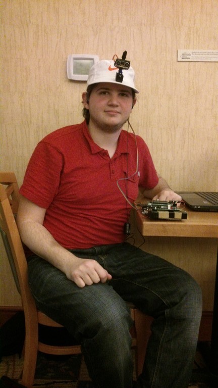
Ultrasonic Pathfinder
Introduction:
Our final project for
the ECE 4760 course consists of a wearable device to provide aid for
the visually impaired. An ultrasonic distance sensor located on a hat
collects data of the surrounding environment scanning the area ahead of
the user, and uses this data to give an audio feedback through stereo
headphones. Using the principles of human sound localization this
feedback provides information on the location and distance of the
obstacles around the user by changing the angle and intensity of the
sound produced. The goal of this project was to create a device that
would help visually impaired people to move around with more ease,
helping them place walls, doorways and obstacles sooner than they would
if they were using only a walking stick.

High
Level Design
Rationale
and sources of
the project idea
This idea came from the
will of designing a simple yet useful device that could be used on a
daily basis and would help people improve their quality of life. After
some thinking and several other ideas, we thought that this was the one
that better fit our goals and would be a very nice project to work on.
Background
math
The physics and math of our project are based heavily on the way sound
waves travel through air and the way our hearing system locates the
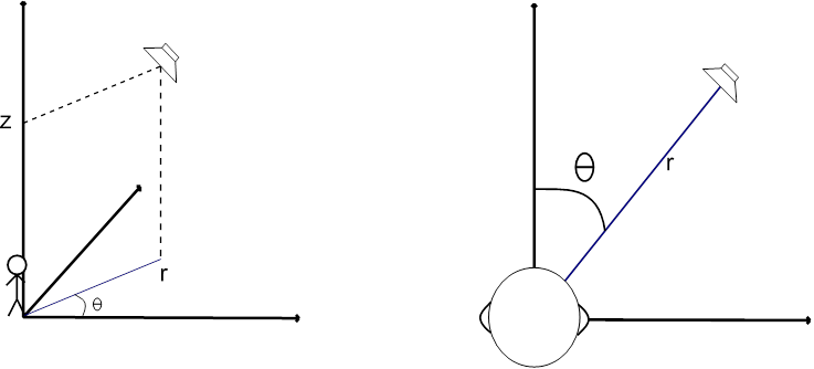
source of a sound. If we imagine ourselves sitting at the origin of a
cylindrical coordinates system, what we are trying to do is to simulate
sound coming from a sound source located at several (r, θ, z)
coordinates. However, we are not worrying about the coordinate z
(height of the sound source) since our sensor will only scan on a two
dimensional manner. Thus, we can simplify this by getting rid of the z
coordinate and assuming our head is located at the origin of a 2
dimensional, polar coordinates system.
Figure
1: Three coordinate and two coordinate systems
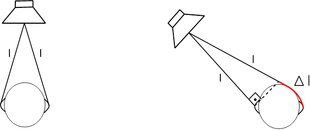
To simulate this, we
must first understand how our brain locates the source of a sound when
we hear it. Basically, it uses two things to do that: Difference in the
time of arrival and difference of sound intensity from one ear to the
other. Imagine a sound source located at coordinates (r, 0), right in
front of the head. The distance between the source and each of the ears
is exactly the same, so a sound wave generated by this source would
reach both of them at the exact same time and with the same intensity.
However, if we change our sound source to a coordinate (r, 45o), for
instance, the length from the source to the left ear is smaller than to
the right, so the sound wave would reach the right ear with a slight
delay in time and also with some attenuation.
Figure
2: Difference between frontal and not frontal sound
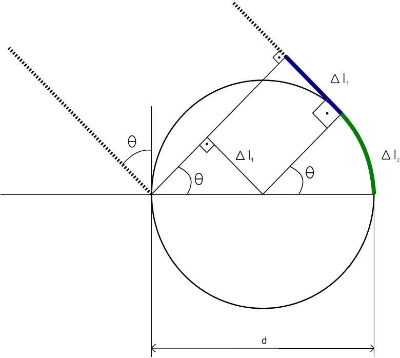
We must then find this distance difference between both paths to find
out how much time passes between when the wave reaches the left ear and
when it reaches the right one for a given angle 900 > θ >
0o. This can be easily done with simple geometry if we make two
simplifications. We must consider the sound source at a distance r = ∞
from the head, so that the paths from the source to each ear can be
considered parallel, and we must consider the head as being a circle of
diameter d, d being the length between ears. The results can then be
duplicated for angles between 0o and -90o.
For these values of θ the path to the
left ear is always shorter, as it is a straight path. For the right
ear, though, the sound will travel straight until it collides with the
head, when it will then by diffraction circle around it until it
reaches the right ear.
Figure
3: Geometry of the head and sound paths
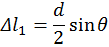
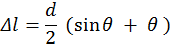
First, we calculate the extra
length Δl1 that the right wave
travels between when the left wave hits the left ear and the right wave
hits the head. According to the figure, we can see that this distance
is given by:
And the distance Δl2 that the
wave travels when circling the
head is given by:
So, the length difference
between both paths, in meters, is:
With d
given in meters and θ radians.
After that, finding the time difference
is pretty trivial, knowing that the speed of sound is 343 m/s.
Logical
Structure
Our project is divided
in two main parts, one being the sound generation and the other being
the sensing and data acquisition. We used two separate MCUs, one
responsible for each of those parts. The sound generation MCU is
responsible for simulating a sound source at different coordinates,
creating two separate sound signals with different intensities,
different start and end times, and exact same frequency. These signals
are then output to an earphone. The sensing MCU is responsible for
rotating an ultrasonic sensor using a servo motor to sweep the area
ahead of the user, and also for collecting and analyzing the data from
the sensor. The two boards communicate to each other via the serial
pins. Information about the angle being measured and the distance of
the obstacle found by the sensor is sent from the sensing MCU to the
sound generation one, which uses it to create the correct time delay
and volume difference between channels. The notion of distance is given
by changing the overall volume of the sound coming from both channels.
An obstacle that is close to the user would make the device generate a
louder sound, while a farther one would result in a lower one.
For the sound
generation, the Direct Digital Synthesis (DDS) technique, introduced to
us in the ECE 4760 Laboratory 4 (Fall 2013), was used. Using the Fast
PWM mode on Timer 0, two outputs are generated on ports B3 and B4
corresponding to the left and right stereo channels respectively. The
two PWM outputs are then low-pass filtered via hardware, what results
in a nice sinusoidal wave to connect to the earphones. These two
channels can be controlled separately, being possible to activate one
and after the correct delay activate the second one. It is also
possible to change the intensity of each one separately, as well as
together. The first is useful to create the volume difference between
channels, while the latter is for the overall volume control.
The audio feedback comes
in the form of a series of beeps that will change in intensity and
location according to the information sent by the sensing MCU. The
location actually reflects the position currently being scanned by the
sensor. So, if the device is gathering information about your far left
side, the user would hear a sound coming from that spot. All the
temporization of this routine is made by Timer 2. It controls the
length of the beeping sound that is sent to the earphones, the interval
between each beep and the delay between the channels. Also, it is this
routine that dictates when the necessary changes in frequency, delay
and volume will occur: Only during the intervals between each beep,
otherwise the user might get confused. The Timer 2 Interrupt routine
consists of a 4 state state-machine that controls the outputs of the
Timer 0 PWM. Every time this ISR is called, the Top value of the timer
is updated to reflect the next time interval that must be counted
(length of the beep, interval between beeps or time delay between
channels), the pertinent channel is turned on or off, and the machine
moves to the next state.
Hardware/Software
Tradeoffs
We opted to use an extra
MCU, and all the hardware that comes with it, to have more processing
power for all the tasks that must be done. The DDS uses a lot of it
since the PWM is always running and its ISR is called very frequently.
Also, since two completely independent sine waves have to be generated,
the ISR takes a long time to complete, leaving not much time between
one routine and the next to perform the rest of the program. Since the
other timing procedures such as the delay time, the motor control and
the distance sensing require some accuracy, putting them all together
on the same MCU might cause some ISR to not be attended, or take too
much time to attend others, which could cause the whole system to
misbehave.
Another tradeoff was to
choose a cheaper and simpler ultrasonic sensor, which required software
distance calculation, instead of a better, more expensive one with an
integrated circuit that would give us the distance already calculated
and ready to use. We came to the conclusion that the few dollars saved
were not worth the trouble of designing and debugging the sensing
program, which showed to be the cause of a lot of issues.
Program/Hardware
Design
PROGRAM
DETAILS
This project was
conceived since the begining to use 2 separate MCUs, in this section we
will talk separately about each MCU software design
SOUND
GENERATION MCU:
In the Sound Generation
MCU routine, the Timer 0 is configured to run at full speed in Fast PWM
mode. Every time the ISR for this timer is called and the outputs are
enabled OCR0A and/or OCR0B values are updated according to a sine table
generated in the initialization of the program. For the intensity
variations a multiplication for a floating point value would be needed.
This would cause the ISR to be so long that a lot of routines would be
lost, resulting in a much lower frequency output due to lack of OCR0A/B
updates. To solve this, other sine tables are created during
initialization, each one multiplied by a gain value corresponding to a
previously defined set of possible angles to simulate. This same method
was used to create predefined values of time delay, audio intensity and
DDS increments, thus saving a lot of processing time on the ISRs. The
tables are indexed at runtime by variables that define the angle of the
sound source location, the volume of the audio, the distance of the
obstacle, etc.
Timer 2 was set to run
with a 256 prescaler, because it was thought that a timing of the order
of hundreds of microseconds was needed for the duration of the beeps.
After some testing it was decided that shorter beeps provided a better
results, but the prescaler was not changed. We had then a precision of
16 microseconds and a range of approximately 1 second. This turned out
to be more than enough time for this application and gave us a
satisfactory precision on time delay timing.
During main, a loop
continuously reads the serial port, waiting for a sequence that
consists of:
- $: A start character;
- alphaL: index of time delay and intensity for the left
channel;
- alphaR: index of time delay and intensity for the right
channel;
- v: index of the overall intensity to be used on both
channels;
Once this sequence is
received, these values are stored in temporary
variables. These
variables are then used by Timer 2 ISR to update the real ones on the
intervals between beeps. Below are the details of Timer 2 ISR State
Machine
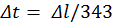
Figure 4: Timer 2 ISR
State Machine
What triggers a change
of state on this state machine is the call of the Timer 2 ISR. Every
the timer finishes counting something the machine will change states.
What the timer will actually be counting and what tasks the ISR is
going to perform depends on the state itself.
State
OFFTIME:
This
is the state the machine is on when no beep is playing. It’s the
interval between beeps. When the Timer 2 finishes counting this
interval the ISR is called and the first thing it does is update the
index variables, getting the values from the temporary ones and moving
to the ones that will be used by the DDS and the other states of this
machine. That being done, the ISR will check for the angle that has to
be generated by the sound. If the angle is zero it turns on both audio
channels at the same time and then updates the Top value of the timer
with the one corresponding to the duration of the beep and the state
changes to ONTIME. If the angle is not zero it will instead turn only
one of the audio channels and set the Top value of the counter with the
necessary delay for the desired angle, and will change the state to
DELAYON
State
DELAYON:
When
the timer finishes counting the time delay the ISR will turn on the
other audio channel, update the Top value with the duration of the beep
and change the state to ONTIME.
State
ONTIME:
Once
the duration is met, it is time to turn the audio off. The ISR will
first check if the angle is zero. If it is, both channels will be
turned off and the Top value will be updated with the interval between
beeps. The state is then changed to OFFTIME. If the angle is not zero
only one channel will be turned off, and the Top value will be updated
with the delay between channels instead. The state will in this case
change to DELAYOFF.
State
DELAYOFF:
When
the timer finishes counting the time delay the ISR will turn off the
other audio channel, update the Top value with the duration of the
interval and change the state to OFFTIME.
The serial communication
was by far the most difficult part. While the DDS, state machine and
timing were pretty straightforward since we had already had some
experience with it, serial communication between two MCUs turned out to
be not that simple. We had a lot of issues especially on the receive
side, which would not recognize the characters sent by the sensing MCU.
It took us hours to realize that it wasn’t working because the getchar
implementation of the uart.c program we were using (the one available
at the ECE 4760 webpage) was focused on communication with a computer,
expecting a line feed to finish reading the buffer. We were not sending
this linefeed, so the program would never stop reading it. We started
sending a linefeed then, and it worked for a while, but after some time
it gave us more problems and we couldn’t figure out what was wrong. So,
we decided to use a different implementation of getchar, and it worked
at first try.
SENSING
MCU
As stated before the sensing MCU was divided into 2 modules other than
the main execution, which are servo_controller and
ultrasound_controller.
Main_loop:
The
main loop initializes the other modules and works by looping through an
array of angles. In each loop it sets the servo to position, measures
the distance, sends output to the sound generating mcu for each angle
in ascending order, then each angle in descending order (not repeating
the extremities). The expected behavior of this should be that the
measuring and servo rotation should take the same amount of time for
each angle, and use a delay between readings to regulate the time spent
in each angle.
servo_controller:
The
servo controller produces a PWM to control a servo motor. The PWM has a
total period of TOTAL_PERIOD (20000ms), and a high-level period between
MIN_ANGLE(600ms) and MAX_ANGLE(2600ms). The duty-cycle value translates
into the servo in angle, having a linear behavior between 0 (MIN_ANGLE)
and 180 (MAX_ANGLE) degrees. Due to its very small variation in
duty-cycle we cannot obtain this PWM directly from any peripheral in
the MCU used, we had then to resort to generating the PWM by changing
the output of SERVO_PIN(pin C1) based on a software counter and a 20us
base interruption with timer0.
servo_controller
provides only 2 routine calls, servo_initialize() which initializes the
necessary registers and servo_set_angle(int angle) which changes the
PWM high-level therefore changing the servo angle.
ultrasound_controller:
The
ultrasound controller uses timer 2 to create the time base for using
the ultrasonic sensor. To read the ultrasonic sensor we need to send a
pulse of 10us on ULTRASOUND_TRIGGER_PIN(pin B1), after that the sensor
will set its ECHO pin (pin B0) while the reading is active and clear it
when finished, the time of this pulse will be the time of the
measuring. To capture this time we enable Pin Change Interrupt on pin
B0, once the bit is set the interrupt service starts a counter, when
cleared it stops the timer and saves the result. To provide a reliable
timing the function that executes these actions and uses the result
uses an enforced reading timer, if the reading finishes before the
timer it will wait for the timer to end, else the timer will act as a
timeout forcing the reading to end and using the timer value as result;
ultrasound_controller provides only 2 routine calls,
ultrasound_initialize() which initializes the necessary registers and
ultrasound ultrasound_read(uint16_t period_in_us) which executes a
measurement taking period_in_us us and return the measurement result in
us.
The complete code can be
found in Appendix A.
HARDWARE
DETAILS
Both MCUs are connected
on the board which design is available at the course website. These
boards, in their turn, are plugged on a perforated board, where extra
hardware is soldered.
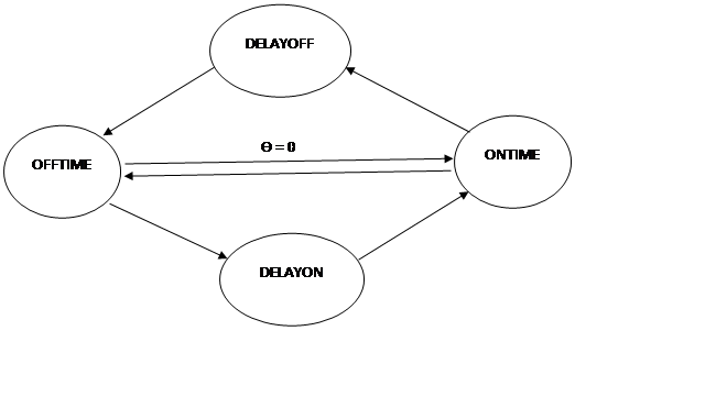
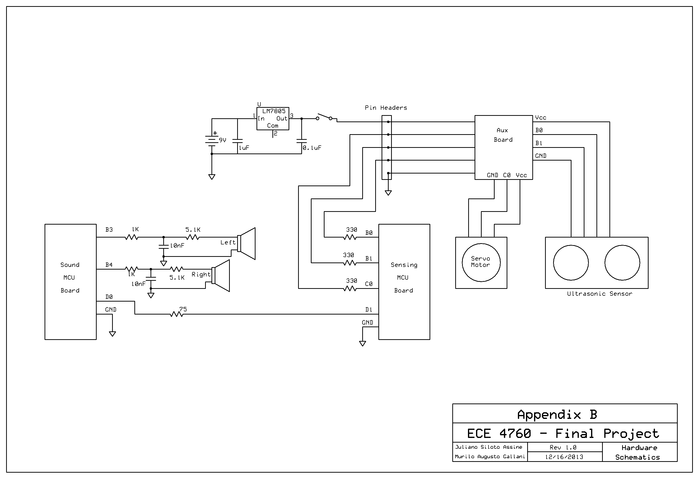
Pins B3 and B4 of the
sound generation board are each connected to a low pass filter
consisting of a 1kΩ resistor and a 10 nF ceramic capacitor. Following
this filter is a 5.1kΩ resistor and the 3.5mm audio jack. This last
resistor is for attenuation and debugging, since it allows us to
measure the filtered output with the oscilloscope and listen to it at
the same time. Pins D0 and D1, the serial pins, are connected to pin
headers. They can be connected with jumpers to the serial pins of the
sensing board. In addition to that, we included 75Ω resistors on the
serial connection to avoid unexpected damage due faulty behavior.
A separate power input
was soldered on the board to provide power to the servo motor and
sensor. The power input goes through a LM7805 voltage regulator, with
capacitors connected across both input and output, just like the ones
on the MCU board. The 5V output goes then through a switch, and from
there to one of a 5 pin header set. The other four pins are
connected to the shared ground and pins C0, B0 and B1 of the sensing
MCU board, the last three through 330Ω resistors. This 5 pin set is
connected through a flat cable to a tiny perforated board that divides
them into 7 others: Vcc, Ground and C0 to a 3 pin header set, and Vcc,
Ground, B0 and B1 to a 4 pin header set. The 3 pin set is connected to
the servo motor through another flat cable and the 4 pin set is sent to
the sensor in the same manner.
Each of the MCU boards
and the Motor/Sensor are powered by individual batteries, a total of
three. They all share the same ground.
Our first try had been
to power both boards with the same battery through the same LM340LAZ-5
regulator, and the motor and sensor through a second one. This failed
and we realized that the current output of 100mA of the regulator was
not enough for either case.
The complete Schematics
can be found in Appendix B.
EXTERNAL
HARDWARE AND
TIMING CONSIDERATIONS:
The main components used
in our design other than the MCUs were a servo motor (SG90 by TowerPro)
and an ultrasonic distance sensor (HC-SR04 by SainSmart), here we will
discuss some of the technical details and practical considerations we
had to take into account with these components, all data mentioned here
can be found in the related provided documentation.
TowerPro
SG90:
This
servo was chosen because of its
price and angle span (180°), basically any other mini or bigger servo
would be enough for this application as long as it has at least 180°
span.
This servo is controlled via PWM with 20ms total cycle. No reliable
documentation was found for control operation but we were able to
determine empirically that the controlling range would be pulses of
approximately 600-2600us with angle increasing with width.
The operation speed is of 0.12s/60° at 5V with no load, as we used a
150° span this would account for a theoretical minimum period of 0.6
seconds
SainSmart
HC-SR04:
This
sensor was chosen because it had the best value in range of work (up to
4m).
This sensor works by sending a 10us pulse to the trigger pin, it will
then start measuring and set the echo pin to 1 while the measure is
taking place. The result in meters is directly proportional to the time
the echo pin is 1.
Assuming the speed of sound is 340m/s it would take 10ms to make a
measurement of 1.7m (10ms for the sound to go to and come back from the
object). To prevent making a reading for too long it has its own time
out after 38ms
Scan
time:
To
ensure an even reading time we enforced the timing of each reading to
be constant(ULTRASOUND_READ_TIMEOUT). We used for our application the
angles between 15° and 165° in the following order(90° being the
center): [15 30 45 60 75 90 105 120 135 150 175 150 135 120 105 90 75
60 45 30], n_angles = 20.
Our expected scan time (time for the sensor to scan forth and back)
with ULTRASOUND_READ_TIMEOUT=30ms is:
scan_time =
ULTRASOUND_READ_TIMEOUT*n_angles + 0.6s
scan_time = 30*20 + 600 = 1200ms = 1.2ms
Results
Our design had satisfactory
results in terms of the basic goals, it is possible for a person to
walk in a room with large objects and smooth surfaces with closed eyes,
but a real life application of the device would need much refinement.
Due to the nature of the progress we don’t have any simple way to
measure our success but the whole project is built around being able to
measure correctly the angle and distance of objects in front of the
user and provide this information to the user with the use of sound
alone, and that is what we will try to analyze.
We were able to
successfully set the servo at a given angle and measure the distance
with the sonar, after that we moved on to trying to scan the frontal
area by setting the angles back and forth. In our first iterations we
didn’t use any way to control the time spent measuring each angle, that
way the measuring time would be proportional to the distance read,
although that would speed the process we found that inconsistency in
read times would leave the user more confused with the audio feedback,
so we moved to enforce a constant reading time by blocking the main
process until a timeout no matter the reading result, in a way that
made the feedback easier to the user to comprehend but was a problem
because it slowed down the reading to the maximum time possible, or
else we would start to lose all readings after the timeout.
Other apparent problem was
due to the servo moving mechanism, readings made when the servo was
moving had much higher loss rates than those made when the servo was
still, so we had to introduce an delay between the servo function call
and the distance measurement, and that plus the starting and stopping
in the servo engine slowed furthermore our scanning time.
Most of the timing settings
can be set in compile time and tweaked, in our demonstration settings
our device was able to scan an area of 150 degrees in front (clockwise
and counterclockwise) of the user in about 2 seconds, with a 15 degree
resolution. The audio feedback consisted of beeps of 30ms with 30ms of
interval between each beep. This value came after several different
tests to find out what kind of beeping would be the best for this
application. At first we tried long beeps of about 100ms with 100ms
intervals, but this turned out to be a little confusing since between
two adjacent beeps the sensor would have traveled a longer distance
than intended. After trying different values of duration and interval
we decided that a series of very fast beeps would be better, since the
sound would feel more continuous and easier to follow. But we found a
lower boundary for that duration. At 20ms the frequencies would be
distorted and the quality of the sound would decay, so we settled for
30ms beeps.
A different approach that
we followed at first for this project was to give the distance feedback
by changing the pitch of the sound instead of the intensity. After a
lot of different pitch configurations the results were still not good.
We found that creating a relation between distance and pitch was very
difficult for people. So, we decided to vary the volume instead and the
results were much better. After some thought we realized that
associating louder and quieter sounds with proximity was much easier
since this is how it happens in real life. We naturally assume that
louder sounds are coming from sources located closer to our ears. So we
stuck with this design and were happy with the results.
Professor Bruce tried our
device, wearing it and trying to move around the corridor with his eyes
closed. He managed to do that without hitting any walls, identified a
door and was able to locate a corner when he reached an open space by
the end of the hall with a nice precision, what made us very confident
of our design.
Conclusion
In the end we feel that
our project met our expectations. Powered by batteries, and with the
sensor attached to a hat, it is something that people can wear and not
worry about the availability of a nearby power source. Also, we think
that the feedback was satisfactory and, after some training and
learning, it would be possible to use this device to find obstacles
with ease. Our goal of creating a device to help the visually impaired
therefore was reached.
However, it still has
room for improvement. Switching the sensor and servo motor by a set of
several smaller sensors would have given us better battery life and
made de device more wearable and discreet. An overall smaller device
would have given us the option of placing everything on the hat, making
it way more portable and convenient, also, a larger number of sensors
would parallelize the readings relaxing the timing constraints that so
far are too slow to be of practical use.
As far as safety is
concerned, we took measures to avoid any electrical shock or short
circuit on the board. The batteries are all connected to the
boards trough reliable connectors and there are switches to easily turn
the power on and off without the need of unplugging wires. The motor
and sensor are well attached do the hat and do no harm to the user.
However, this is just a prototype there is no guarantee that the user
will not get hurt if relying only on this device when moving around,
specially the visually impaired. So, even though the device itself is
safe, it cannot and should not be open to the public without further
testing and improvement.
Intellectual
property
considerations.
In this course we reused and modified code from across the semester, be
it code written for previous projects or code provided by the course
webpage, but almost all functionality in the project is original. As a
special mention the only codes used covered by some specific license
are the uart codes used for each board:
uart.c and uart.h used for the sensing board project was written by
Joerg Wunsch under the BEER-WARE LICENSE that was provided in
the course webpage
uart.c and uart.h used for the sound generation project was written by
Mika Tuupola under the MIT license
Note: We used 2 different usart implementations because the one
provided by the webpage had excessive functionality that was
dificulting the implementation so we looked for a simpler
implementation.
Ethical
considerations.
During the course of this project, from the first design stages to the
writing of this report, we attained to the IEEE Code of Ethics. We
assure that our tests were done in a safe and controlled environment,
and with safe practices that by any means put in danger our colleagues,
the lab staff, ourselves or any other person that happened to be around
us at the time of the tests. We guarantee that this report contains
only true data, and the work here related was done by ourselves or
otherwise credited and noted. We are aware of the projects problems and
do not try to hide it, we know that our project may be dangerous to the
user if defective and throughout the development we prioritized
accuracy over practicality to increase the overall quality instead of
being able to deliver something fast. During the course of the project
mistakes were made, since de basic ideas of the project until the
development of hardware and software, but, like the IEEE Code of Ethics
suggests, we accepted those mistakes and gave our best to change what
we could to improve the design, taking into consideration the ideas and
criticism of our friends, TA’s and Professors.
Legal
considerations
Until the moment of this writing we were not aware of breaking any laws
and our project doesn’t interfere with the working of any other device.
APPENDIX
A - Source Codes
Sensing
MCU software:
Sound
Generation MCU
software
APPENDIX
B - Schematic
APPENDIX C - Parts Cost
| Part |
Vendor |
Unit
Price |
Quantity |
Price |
| TowerPro SG90 |
Amazon |
$
3.00 |
1 |
$
3.00 |
| SainSmart HC-SR04 |
Amazon |
$
5.00 |
1 |
$
5.00 |
| 9V Battery Connector |
Amazon |
$
1.56 |
3 |
$
4.68 |
| 3.5mm Connector |
Digikey |
$
0.68 |
1 |
$
0.68 |
| 6’’ Solder Board |
ECE 4760 Lab |
$
2.50 |
1 |
$
2.50 |
| 9V Battery |
ECE 4760 Lab |
$
2.00 |
3 |
$
6.00 |
| Custom PC Board |
ECE 4760 Lab |
$
4.00 |
2 |
$
8.00 |
| Mega1284 |
ECE 4760 Lab |
$
5.00 |
2 |
$
10.00 |
| Header/Plug |
ECE 4760 Lab |
$
0.05 |
107 |
$
5.35 |
| 330Ω Resistor |
ECE 4760 Lab |
$
- |
3 |
$
- |
| 1KΩ Resistor |
ECE 4760 Lab |
$
- |
2 |
$
- |
| 5.1KΩ Resistor |
ECE 4760 Lab |
$
- |
2 |
$
- |
| 75Ω Resistor |
ECE 4760 Lab |
$
- |
1 |
$
- |
| 1uF Capacitor |
ECE 4760 Lab |
$
- |
1 |
$
- |
| 0.1uF Capacitor |
ECE 4760 Lab |
$
- |
1 |
$
- |
| 10nF Capacitor |
ECE 4760 Lab |
$
- |
2 |
$
- |
| Power Plug |
ECE 4760 Lab |
$
- |
1 |
$
- |
| Flat Cable |
LASSP Stock Room |
$
1.80 |
1 |
$
1.80 |
| Earphones |
Pre-owned |
$
5.00 |
1 |
$
5.00 |
| LM7805 |
RadioShack |
$
2.00 |
1 |
$
2.00 |
| Hat |
TJMax |
$
7.00 |
1 |
$
7.00 |
| Total |
|
|
|
$ 61.01 |
APPENDIX D - Work Division
During this project both of us worked together during the whole
process, but, naturally for a project with two very distinct parts, one
was more heavily involved with the sound generation part while the
other worked more on the sensing side of the project.
Juliano Siloto Assine:
-
Design and implementation of the servo motor controller software
-
Design and implementation of the ultrasonic sensor interface
-
Soldering of the Sensing MCU Board
-
Mechanical assembly of the device
Murilo Augusto Gallani:
-
Design and implementation of the sound generation code
-
Soldering of the sound generation MCU
-
Design and soldering of the general hardware board
Any other action not
listed, such as report writing and device testing had a large
contribution from both.
APPENDIX E - Datasheets