"A pointing device controlled by webcam object detection and tracking"
For our ECE 4760 final project, we designed and built a pointing device with webcam-color-tracking based movement control. Our implementation allows the user to wear a set of finger-sleeves complete with buttons for clicking and scrolling and a red LED for color-tracking cursor control to interface with a computer as a normal mouse would. Users have the freedom to control their computer’s cursor movements and functions simply by moving a hand in the air without the need for a desk.
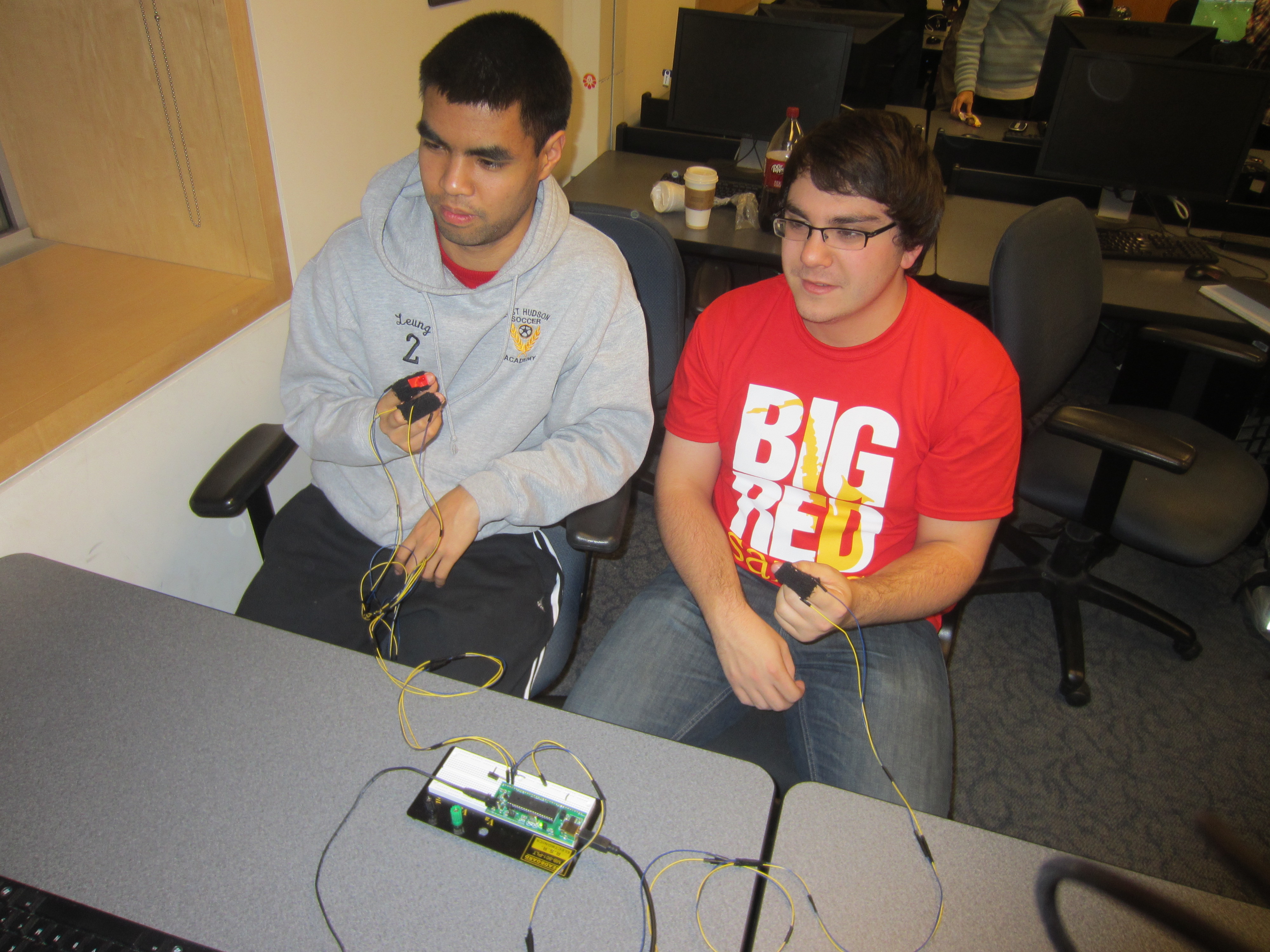
Students Miles Pedrone and Alex Leung
Video demonstration
High Level Design
Rationale and Project Conception
For our final project, we wanted to do something that we thought would be interesting and could have practical functionality in day-to-day life. After some brainstorming and browsing of projects from previous years, we decided to do our own take on a pointing device that would track a user’s movements and act as a replacement to the mouse on a computer. Past groups have shown that hands-free mouse control can be achieved through the use of accelerometers to coordinate mouse movement. As such, we hoped to explore some other means of mouse position generation that haven’t been acted upon in previous years.
Initially, we explored two different ways to control cursor movement. The first was to use an array of infrared LEDs and infrared receivers to track intensity and transfer these relative changes to changes in mouse position. The second was to use a webcam and color-tracking to detect an object and track its movements. After discussing the tradeoffs of each design and some experimenting, we decided to move forward with the webcam design. Ultimately, our intent for this project was design a hand-motion based mouse that would be built around a different design than ones that are available in the market and ones that have been done in the past by other groups.
Another design choice was to use finger sleeves instead of gloves to house the buttons and red tape for color tracking. The finger sleeves allowed for a more natural typing experience since the finger tips were left exposed whereas the gloves felt weird and unnatural.
Logical Structure
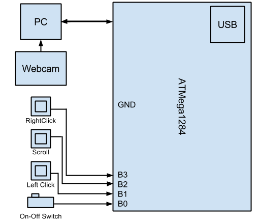
At a high level, our project consists of five main components: a webcam, three finger sleeves, a microcontroller, an on-off switch, and a Matlab interface. Each finger sleeve is fixed with a button and one of these sleeves is fitted with red tape for color tracking. The buttons provide left click, right click, and scrolling functionality and are wired to the microcontroller. Operation of the device begins with the finger sleeves and the webcam. The webcam is mounted in a convenient location and is connected to one’s computer. A user wearing the finger sleeves moves the finger with the red tape in the field of the webcam. The webcam tracks the centroid coordinates (x- and y-) of the red tape as it moves in its field of view through a Matlab interface and sends these coordinates to the microcontroller via serial communication. Upon receipt of this data, the microcontroller scales the coordinates to the resolution of the computer screen and encapsulates these with the button presses into a packet sent back serially to Matlab. Finally, Matlab unpacks the packet and interfaces with the computer with cursor movement, button clicks, and scrolling as one would expect of normal mouse. The on-off switch is for turning cursor movement off if the user wants to type on the keyboard without the annoyance of a moving cursor. All button functionality is still on even if the switch is turned off.
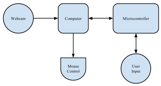
High-level block diagram of the system
Hardware/Software Tradeoffs
We found the use of the finger sleeves fitted with the push buttons to be refreshingly natural to use for both mouse control and typing compared the use of gloves fitted with the push buttons, which was our initial idea. The finger sleeves leave the finger tips exposed, allowing for a more natural-feeling when typing while the covered finger tips when using the gloves made typing awkward and uncomfortable. Additionally, the finger sleeves can easily be moved to different fingers to allow for a more personalized experience that better fits your needs and preferences in terms of button functionality.
From project conception, we knew that there were a couple of routes that we could take when it came to interfacing our webcam mouse with a computer. Simply put, one way involved the use of additional hardware in the form of a USB HID-compatible microcontroller and the second way involved a software interface using Java libraries in Matlab. After some discussion, we ultimately decided to take the software-based approach for mouse control and control cursor movements and clicks through Matlab. Intuitively this made sense to us, since Matlab would already be used for image acquisition from the webcam. Additionally, taking this approach allowed us to avoid the complexities of incorporating an additional microcontroller and incurring the costs associated with its implementation. The software approach proved to be a good decision.
When discussing the approach we wanted to take in controlling the mouse, we quickly realized that we could do so with either hardware or software. In using hardware, we would have to track the user’s movements and communicate this to the PC with an additional microcontroller. More importantly, after researching this implementation we chose not to do so due to complexity of implementation. Because we were interested in a webcam-based interface, we chose instead to utilize a software implementation to track the user which doesn’t require that communication. This would make calculation of the coordinates much easier, but also makes the image processing mandated by the webcam realizable. Given the small processing power and memory on the microcontroller, we didn’t believe it would be feasible to try to do all of these calculations onboard. Instead, we used the microcontroller’s ability to register user inputs on the order of microseconds to record the button presses.
Initially, when discussing webcam object tracking, we were posed with the design choice of tracking an object based via color or infrared. The former option would be easier to implement but be prone to tracking errors while the latter option would provide more robust object tracking at the expense of complexity. Given our time constraints for the project and the sufficiency of color tracking, we made the decision to go with color tracking over infrared tracking. Due to benefits of IR tracking, we discuss this at a later time in our conclusions as a possible extension.
Standards
Since our device would have to be recognized by a computer as a human interface device, we initially planned to use the USB HID protocol and thus would have to abide by the USB HID protocol specifications. However, we realized that interfacing the microcontroller with the computer would be made simpler if we used serial communication to send and receive data. By choosing serial communication, we were able to define our own packet structure and implement mouse control through the help of the Robot object in the Java library. The Matlab image hardware acquisition (imaqhwinfo) Toolbox was used for image acquisition from the webcam, which adheres to all standards for video communication and processing. We also adhere to the UART protocol by using prescribed 9600 baud rate as detailed on the microcontroller specification sheet. We use the UART code provided by the ECE 4760 course website linked in the Appendix.
Copyrights and Acknowledgements
Although we consulted past projects when initially trying to decide which project to do, we did not consult any of the projects for any portion of our own design. That being said, we did find and consult a very helpful open source Matlab project by A. Bhargav Anand on Matlab’s MatlabCentral File Exchange regarding red-colored-object tracking and a real-time processing in Matlab example by a man named Jerome Lecoq on Matlabtips.com. We were able to build off of these two code examples for our image acquisition and processing. Links to these two resources are provided in the Appendix.
In developing our C code, we used the Tiny Real Time kernel developed by Anton Cervin. To build our website, we adapted a Cornell template used by Adam Papamarcos and Kerran Flanagan, another project team that that developed “Human Tetris” in Spring 2010. Links to these references are provided in the Appendix. Further discussions of intellectual property and copyright laws are discussed in our conclusion.
Hardware Design and Implementation
Hardware Overview
As noted above, the physical design of our project has four main hardware components: a webcam, three finger sleeves with buttons, a microcontroller, and an on-off switch. The webcam tracks red-colored object movement of the finger sleeves and communicates centroid coordinates to the microcontroller via Matlab. The microcontroller encapsulates scaled coordinates and button presses from the finger sleeves into a packet and sends the data back to Matlab for mouse functionality. The on-off switch toggles cursor movement on and off.
Webcam
The Webcam
The webcam we used for our project is a used Microsoft VX-3000 Lifecam with a 640 x 480 pixel resolution. It captures images at a rate of 30 frames per second and is connected to the computer via USB. The webcam, interfaced with Matlab, is used to track red objects and their movements in its field of view.
Finger Sleeves
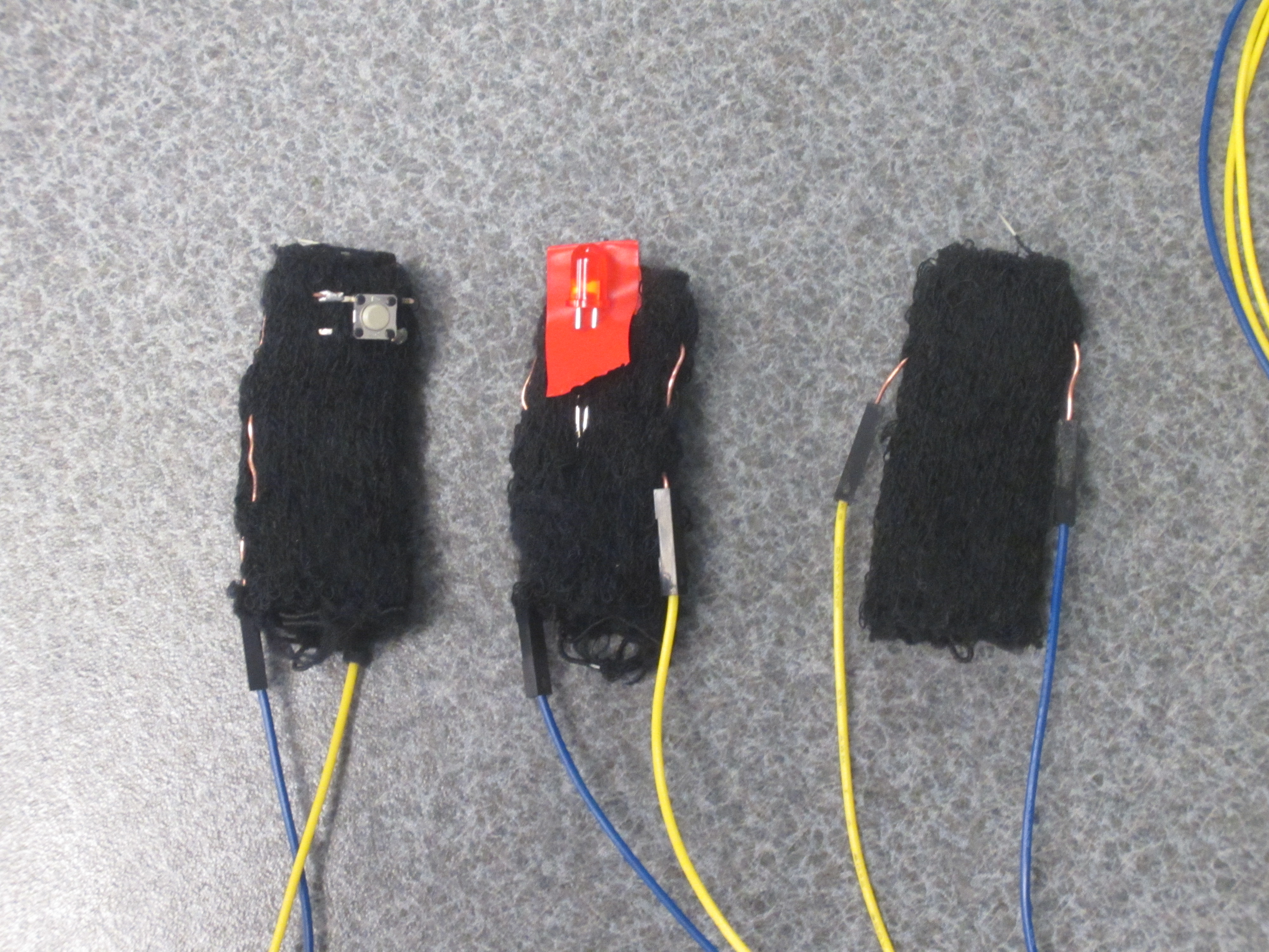
Finger Sleeves
The three finger sleeves we use are just typical black knitted elastic finger sleeves. On each finger sleeve, we fit a push button for mouse click functionality. The sleeve on the right pointer finger has a push button that functions as a left click. The sleeve on the left pointer finger has a push button that functions as a right click, and the sleeve on the right middle finger has a push button that functions as a scroll. The right pointer finger sleeve is also fitted with a piece of red tape to be picked tracked by the webcam.
To connect the finger sleeve push buttons with the microcontroller, we use an active-low Pin B.1, B.2, and B.3 on the microcontroller. The left click button is connected to Pin B.1, the scroll button is connected to Pin B.2, and the right click button is connected to Pin B.3, all with header-pin wires. The diagonal lead of the buttons are connected to ground for the active-low ports.
Buttons
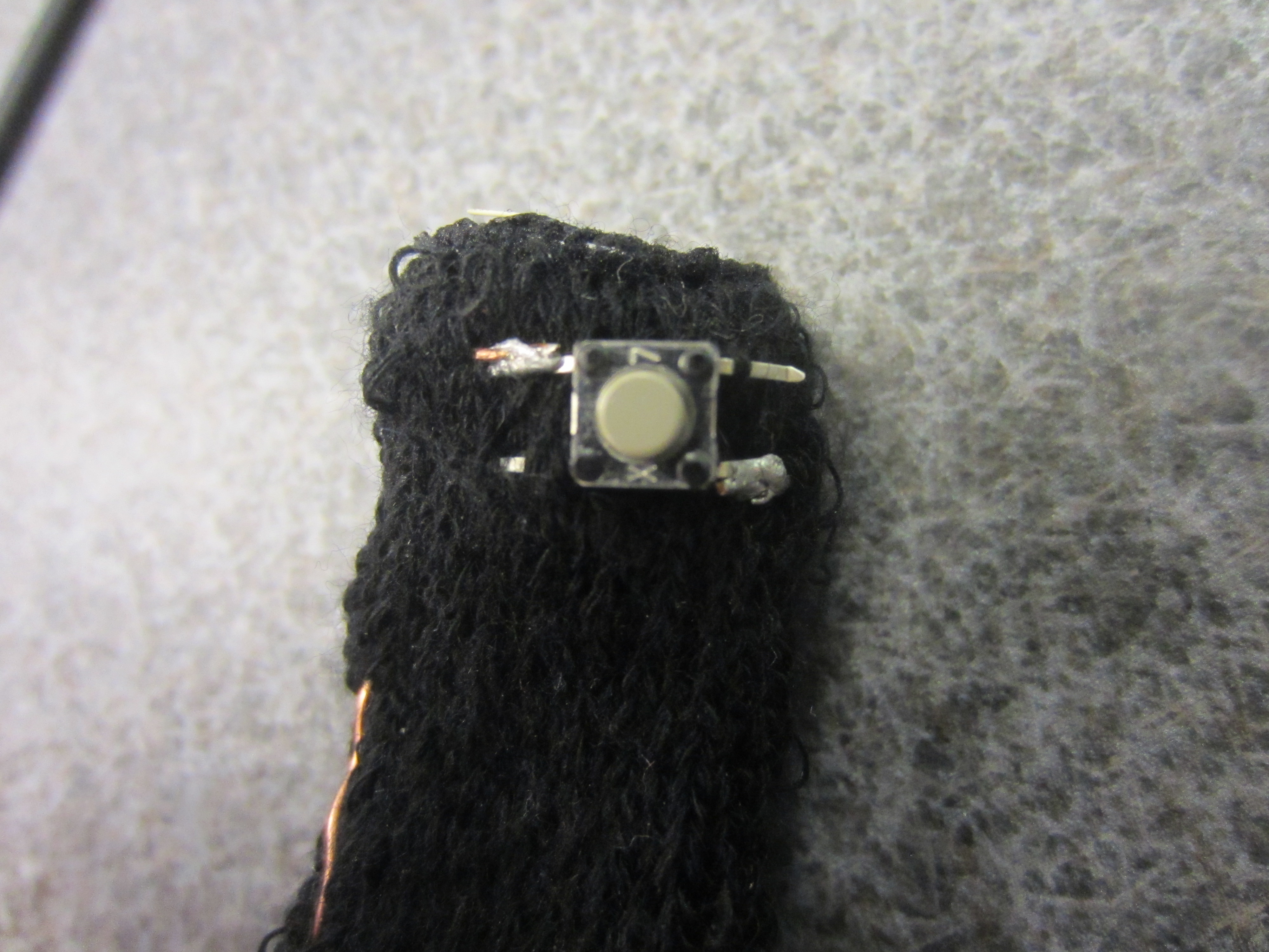
The Buttons
We chose to use typical four-lead push buttons in order to detect our mouse button commands. When the push button is pressed, the leads that are diagonal from each other are shorted together. The buttons are connected to the microcontroller via one lead to the microcontroller pin and the diagonal lead to ground.
After some experimentation and oscilloscope tracing, we determined that our buttons did not require debouncing since they were resistive enough to short the leads only when completely pressed without any jumps.
Microcontroller
The microcontroller that we use is an Atmega1284 mounted on a custom prototype board with serial communication. A link to the hardware setup is located in the Appendix.
On-Off Switch
The on-off switch is connected to Pin B.0 and ground. Its purpose is to toggle the cursor movement on the screen of the computer on and off. This is most useful for when the user wants to type on the keyboard without the webcam tracking the movement of the finger sleeve and thus annoyingly moving the mouse cursor. The push buttons on the finger sleeves are still fully functional and still allow the user to click and scroll even if the switch is off.
Trials and Testing
The main hardware testing that we did was for the push buttons. Since the push buttons had four leads instead of two, we wanted to ensure that they were being used correctly. To ensure this, we tested all combinations of leads using an oscilloscope to show the output. Through our testing, we finally deduced that leads opposite each other were shorted together when the button was pressed. Also with the oscilloscope, we noticed that the buttons did not have to be debounced since the output signal was very clean.
The rest of the hardware was plug-and-play, working as initially expected and not needing additional tests.
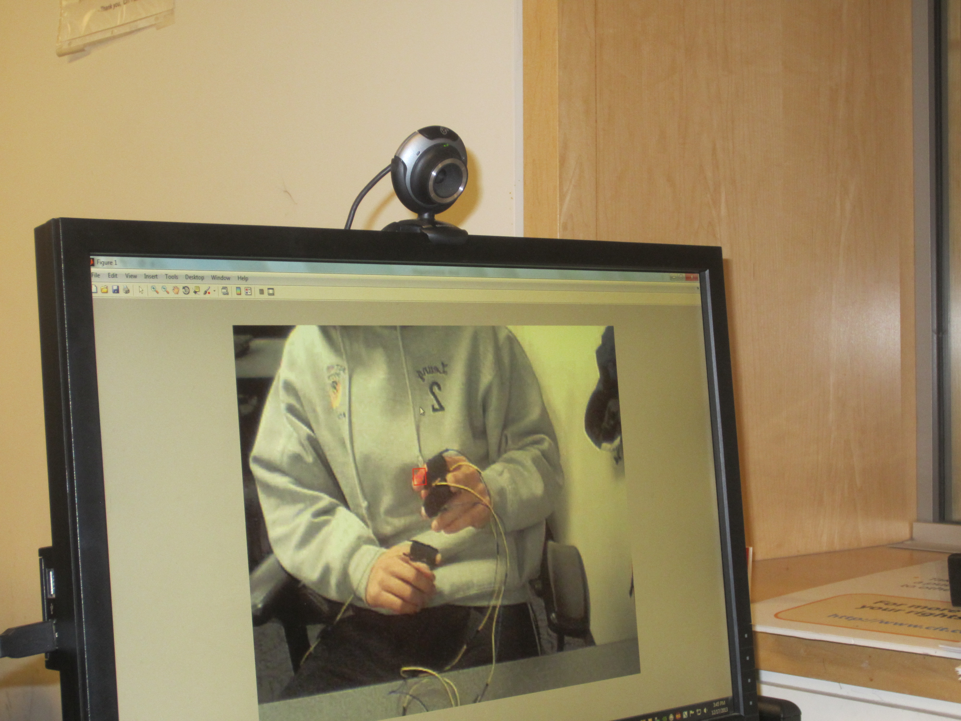
![]()
The mouse in action
Software Design and Implementation
Matlab Code
As briefly discussed in our high-level design section, our Matlab code takes care of the pre- and post-processing of the mouse control. To communicate with the webcam, we utilize the Image Hardware Acquisition Toolbox (imaqhwinfo) and create a videoinput object. This allows us to trigger a function call at a fixed interval faster than the frame rate ensuring we never miss a new frame to be analyzed. We referenced previous work by MathWorks’ FileExchange for red object detection and Jerome Lecoq for real-time analysis (referenced in the Appendix) in developing the image processing and real time tracking code explained below.
Object Tracking and Centroid Extraction
In the call to the triggered MouseControl() function, we complete all of our image processing and then communicate with the microcontroller. After flipping the image so it acts like a mirror, we begin by extracting all data that isn’t red with the following built-in Matlab function:
   data = flipdim(getsnapshot(vid), 2)
   diff_im  imsubtract(data(:, :, 1), rgb2gray(data))
Data holds the snapshot (the current frame) for all x, y, and z data. Here, we keep all x and y data and only extract the first z value for each which corresponds to the red information in the red/green/blue (RGB) format. It then converts this to grayscale (binary) data, essentially mapping the specific color to a number. After this step, we then apply a median filter to the data in a 5 x 5 pixel area which removes noise. After experimenting with different areas, we found that 5 x 5 was a sweet spot for this specific webcam.
With this accomplished, we can begin finding the objects within the frame. This involves converting the image to a binary image by setting a threshold for 0’s and 1’s:
   diff_im = im2bw(diff_im, 0.20)
   diff_im = bwareaopen(diff_im, 16)
   bw = bwlabel(diff_im, 8)
This threshold (0.20) was also heavily experimented with. If this is too low, parts of the frame with very little red content are grouped together. If it’s too high, it aggressively removes part of the image which we want to keep. The bwareaopen() command analyzes the binary data and finds connected components of red, i.e. distinguishes significant red objects. This is why the threshold of 0.20 is so important as it allows us to find the correct amount of discretion when analyzing the data. Finally, we label the connected components with the bwlabel command.
At the end of all of this image processing, we have found all significant red objects on the screen. The list in bw ranks them by their size and picks between objects of equal size by its proximity to the top-left of the screen. Using the regionprops function, we can extract the centroid of each object and send the corresponding x and y positions to the microcontroller.
stats = regionprops(bw, 'BoundingBox', 'Centroid')
For debugging and development, we displayed each frame and its centroid with bounding box in order to find the correct parameters for our image processing. In our final code, we do not display the video and only extract the centroid to avoid the bounding box calculation.
Serial Communication
With the absolute position information extracted, the function then uses the serial object below to send the position packet to the microcontroller:
   s = serial('COM8', 'Parity', 'none', 'FlowControl', 'none', 'BaudRate', 9600)
   fprintf(s, '%d %d\n\r', [round(bc(1)) round(bc(2))])
The serial object created is the most crucial connection of our project as it allows the microcontroller and Matlab to communicate. The settings above allow us to use the fscanf() and fprintf() functions to send packets and receive them with a 9600 baud rate. We experimented with other rates, but 9600 proved to be the most reliable. The arguments bc(1) and bc(2) are the x- and y-positions of the tracked object and are the entirety of the packet we send to the microcontroller. This was a design choice because we wanted the microcontroller to calculate all of the mouse controls. After sending the position packet, Matlab waits on processing done by the microcontroller and return data with a fscanf() function call. We chose to have the function timeout after 2 seconds if it hasn’t received a packet which made debugging easier. After it has received the packet from the microcontroller, it unpacks it with the following command:
in = fscanf(s,'%d %d %d %d %d %d')
From left to right, the packet above holds the following information: x-position, y-position, left click, right click, on-off control, and the scroll command. The on-off value comes from the switch on board the breadboard. If it is low, then Matlab can’t control the mouse. This lets the user keep the mouse stationary while typing or simply lets them turn it off for extended periods of time.
Mouse Control
We used the fact that Matlab can natively run Java to create a Robot object which directly manipulates the computer’s mouse. If the scroll command is positive 1, Matlab knows that to scroll one scroll unit up on the screen. If it is negative one, it scrolls one scroll unit down. If it is zero, the user has either not selected the scroll option or has not moved more than 10 pixels up or down. If the mouse is on, the code will send clicks and scrolls to the Java Robot object along with an absolute position which controls it in real time. After timing this operation with tic and toc, we found that these commands execute very quickly as we expected. The code finally updates the state and exits the function call. It does nothing until the next time-triggered event.
Testing & Debugging
Our first bug involved Matlab crashing due to its memory allocation filling up. Without the timing object to trigger the function call, all of the frames that are analyzed sit in the computer’s RAM and fill it up very quickly. The function call and timer object prompt Matlab to garbage collect these frames, freeing up memory usage. When scanning in the packet from the microcontroller, we spent over two full work days trying to understand why it wouldn’t work only to realize that we needed the \n\r terminator. Without this terminator, the microcontroller’s fscanf() function will never detect an end on the input stream and as a result will wait indefinitely. Another interesting Matlab bug involved the Matlab’s packets to the microcontroller staying in the buffer even after they have been read by the microcontroller. More specifically, the x and y integers need to be read by Matlab before we can extract the microcontroller’s response. This is a confirmed bug that other groups have encountered this year which was solved by simply making two fscanf calls on the data.
Microcontroller Code
TRT Kernel
The microcontroller is running the Tiny Real Time (TRT) kernel which schedules two real-time tasks: one for serial communication with Matlab and a second which listens for button inputs from the user. Although the two pieces of information are acquired separately and must be protected via semaphore, the frequency of their execution is on the order of single milliseconds which allows seamless combination of the information in the Matlab communication task. In this communication task, the microcontroller calculates the scaled position in number of x and y pixels to control the mouse. It then accesses the user input variables to detect a right, left, or scroll request from the user along with an on-off switch selection.
Both tasks execute in a few milliseconds and have a small amount of local variables, which minimizes the overhead of the context switch. Although we could achieve the same functionality by writing solely C code and using ISRs, the TRT tasks both run quickly enough to be executed by the time the next frame is received (33ms). We also found TRT easier to use when developing and debugging the project.
Initialization
Before running the two TRT tasks, the microcontroller must setup its ports and serial communication. We utilized Port B as an input port with pull-up resistors. These allow the pins to return quickly to a value of logic high after discharging to zero volts upon a button press. We utilize trtUart.c, trtUart.h and trtSettings.h provided by Bruce Land (written by Dan Hennriksson and Anton Cervin) for our previous labs to communicate with the PC. We then create and start the TRT tasks with an enough stack space to call fprintf() and fscanf(). We ensured that the pccomm() task had enough space to do floating-point calculations as well.
PC Communication and Screen Position Calculation
After initialization, our first task, pccomm() executes every millisecond according to our TRT release and deadline times. The pccomm task first reads in the x and y position data that Matlab has sent over UART which is setup in initialization as follows:
fscanf(stdin, " %d %d", &x, &y)
Because we have hardcoded the screen resolution of the lab computers, the microcontroller code can use the x- and y-pixel coordinates extracted from the packet to calculate the new absolute mouse position. The accuracy of our device is very high as we have 640 points of precision in the x direction and 480 points in the y direction from the webcam. This means that for a typical monitor display, the mouse can be positioned with 2 pixel precision using floating point arithmetic. This is more than enough to accurately point anywhere on the screen. Before the microcontroller can send its return packet to Matlab, it must encapsulate any user input received.
Because we use a semaphore to protect the user input, the pccomm() task must wait at most a millisecond (plus context switching) to access these data. The buttons used to not need debouncing, so we can directly access the value of PINB to check the bit value of the on-off switch, left click, right click, or scroll. For example, if the user has clicked the left-click button, Pin B’s bits will equal 00000010 indicating that the Pin B.1 is at zero voltage. The essentially sees if the value of Pin B.X is low and if so, either a button has been pushed or the on-off switch it connected to ground. The microcontroller then completes the scroll calculation before sending its packet to Matlab.
Scrolling Calculation
In order to implement touchscreen type scrolling, the microcontroller tracks the most recent y-pixel position. If the change between function calls is at least 10 pixels and the scroll button is held, the microcontroller stores a scroll up (1) or scroll down (-1) value to send to Matlab. This way, the user must move their hand while holding the scroll button to scroll up or down. If they stop moving, it will stop scrolling just like any touchscreen. After this calculation, the microcontroller combines all of this information and sends a packet back to Matlab with the data needed to entirely control the mouse as shown in the format below:
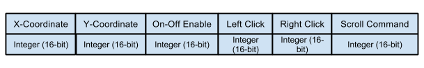
Microcontroller to Matlab Packet
Button Communication
The buttoncomm() task is very short and thus very fast. It has a single state variable which tracks which button has been pressed. We decided to only allow one button be recognized with priority given to left click, then scrolling, then right click. This was after careful consideration of the possible use cases. Very rarely with a traditional mouse does one left and right-click at the same time, or click and scroll at the same time. This made our task faster and the state machine very simple. From state 0 (idle), the initial state, we first check for left clicks, then scrolling clicks, and lastly right clicks in a similar fashion as the left click. We invert Pin B because the buttons are active low. After observing the voltage characteristics of the buttons with an oscilloscope, we decided not to debounce them because they are very robust. For each of the three clicks, we transition to a unique state representing that it had been clicked. In each of these three states, we check to see if the button is no longer pressed. If so, we return back to state 0. This state machine is running constantly and is only interrupted upon context switches to pccomm().
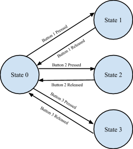
Button State Machine
Results
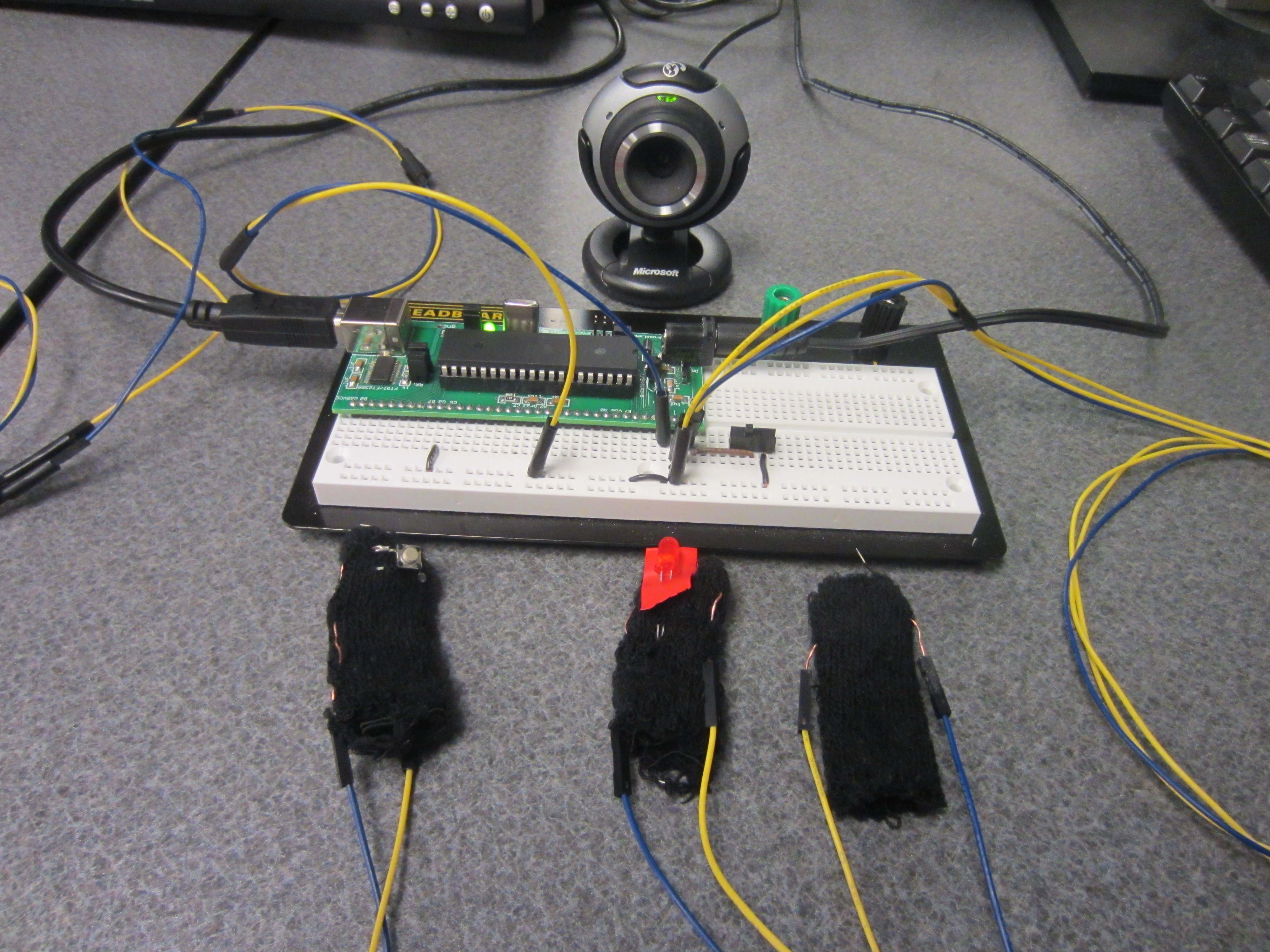
Webcam, finger sleeves, and microcontroller.
Speed of Execution and Usability
We have found our final design to be very responsive with its appreciably small input lag. Because the webcam must identify an object clearly in its field of view, occasional variation in the image of the LED will cause jumps if it can’t be identified. However, because we implemented absolute-value position control, when the mouse next updates it is still where it would have been had the mouse pointer image moved continuously. We have also found that our decision to use finger sleeves makes it much easier to type with the device. In the end, our most significant problems with input lag were due to the TRT timing deadlines. Assuming that the webcam has a solid lock on the image, we can do all image processing in under 20 milliseconds and command the entire frame processing can be accomplished in around 120 milliseconds. Combined with the delay incurred from the button task in TRT and the serial communication delay, latency makes for a very fluid and responsive user experience. The device itself is usable for almost anyone as the user only needs to wear three finger sleeves. They can decide which fingers to put where and they can be worn to position the buttons to their choosing.
One flaw that we found in the usability of our red-object-color-tracking webcam mouse arises when additional red objects other than the red tape on the finger sleeve are present in the field of view of the webcam. When tracking red objects, the code prioritizes by their location in the field of view. Objects with lower coordinate values are given higher priority and, as a result, the webcam mouse would prioritize this object over the red tape object on the finger sleeve. The cursor would instead follow this object instead of your finger, greatly affecting usability. One way to remedy this is ensure that there are no other red colored objects in view of the webcam and make sure to not wear red!
Accuracy
The accuracy of our device is very high as we have 640 points of precision in the x direction and 480 points in the y direction. This means that for a typical monitor display, the mouse can be positioned with 2 pixel precision. This is more than enough to accurately point anywhere on the screen. We initially tried a snap-to-edge feature if the mouse was going to be some minimum number of pixels from the edge, but this didn’t allow for accurate selection of the minimize/maximize/close buttons for a window. After playing around with the scrolling behavior, we have chosen 10 pixels to be a robust threshold for change in position. With this value, the jitter involved with a typical user’s hand will not scroll when the user wants to. This value also works very well for one single scroll unit associated with a mouse as it does not scroll too quickly or slowly for the user. The result is a smooth scroll that behaves the same as typical mouse. Our buttons do not need to be debounced and the TRT task which scans the port pins executes quickly enough that we do not miss any user input.
Safety
Our project is very safe. Because the voltage and current ratings are very low, no harm would come to the user if they were to touch an open wire. The only interaction the user has with hardware is with the buttons which are enmeshed in the finger sleeves. These do not touch the user’s skin and connect to the wires away from the user’s fingers to minimize this chance. The wires we used are long enough to prevent restriction of the user’s motion even if tangled and will simply disconnect if pulled too hard.
Conclusions
Accomplishments and Further Improvements
In conclusion, we would have to say that we accomplished all that we initially set out to accomplish with this project. We were able to design and build a device that is practical in day-to-day life and had fun during the whole process. With every design, however, there is always room for improvement and I will lay out some ideas that we had for extensions.
The big improvement that we would like to make to our webcam mouse is wireless transmission. The current design is overridden with wires that are clumsy, annoying, and frustratingly limiting. In the future, we hope to wire all the buttons to a separate microcontroller connected to a RF wireless transmitter. A RF wireless receiver would be connected to the original microcontroller and then the two microcontrollers could communicate wirelessly between each other. This would eliminate the long wires between the finger sleeves and the microcontroller and allow for mouse control from greater distances.
Instead of using the color red to track an object, an infrared LED and a webcam equipped to receive infrared input data would have made for a more robust design as it would work in a wider variety of environments. The limitations of ensuring that the only red object in the webcam’s field of view is the red tape is a big annoyance and one that is very off-putting to users. The use of an infrared LED and webcam, however, would mitigate this limitation and prove to be a much better design.
The design that could truly be the biggest improvement and prove to be highly functional would be to eliminate the need for the microcontroller and instead interface all the clicks and scrolls through pattern or color recognition with the webcam. Detecting clicks and scrolls through the webcam could possibly be carried out by flashing certain colors or patterns in the view of the webcam and utilizing the object-tracking formula that we are already using. Since the resolution scaling can also be done in Matlab, there would be no need for the microcontroller, allowing for a purely wireless webcam mouse design. This design is the most interesting to us out of the ones proposed and we hope to continue researching and experimenting with this in the future.
Overall, this project was an awesome and satisfying experience.
Intellectual Property Considerations
As discussed in the standards section of our high-level design discussion, we have made use of parts of provided code from Matlab’s MathWorks and Matlabtips.com to implement our image processing and real-time analysis. We also utilize the Java Robot class. As such, we cannot claim to own the intellectual property of our project. Additionally, in designing this website we adapted a template for the website from the Spring 2010 project, Human Tetris, by Adam Papamarcos and Kerran Flanagan.
Ethical Considerations
Throughout all four weeks of this project, we strictly adhered to the IEEE Code of Ethics. We made sure to discuss our project ideas with our TA and Dr. Land early in the project planning phase. Once we began creation of our hardware, we were constantly evaluating the safety of our project for ourselves and any other user. As per Governance 7.8 in the IEEE Code of Ethics, an engineer is required “to accept responsibility in making decisions consistent with the safety, health, and welfare of the public, and to disclose promptly factors that might endanger the public or the environment.” We ensured that all wires were entwined in the outer layer of the finger sleeves away from the user’s skin to prevent injury. With so many other groups also working around us, we also made it a point to have a clean and safe workspace to avoid accidents. When soldering our components, we followed lab procedure and wore proper eye protection. All of our referenced work is appropriately acknowledged and credited on this website. Lastly, we did our best in making realistic design choices and honestly stated the successes and failures of our project in our design and results sections.
Legal Considerations
We do not believe that there are any legal considerations to consider for our project. As previously addressed, all design material we referenced is available to us to use, provided we have the proper citations. Our project does not emit any excessive EMF or produce sound so these issues do not need to be addressed. We do not believe that any of our ideas are uniquely ours in terms of code or configuration as other such mice have been created and thus we do not believe we have patentable content. All of our code provided on this website is free for all to use. References to our work are provided below in the appendix.
Appendix
A. Code Listing
B. Schematic
C. Parts List and Costs
| Part | Unit Cost | Vendor | Quantity | Total Cost |
| Atmega 1284 | $5 | Lab Stock | 1 | $5.00 |
| Finger Sleeves | $6 | Amazon | 3 | $1.80 |
| White Board | $6 | Lab Stock | 1 | $6.00 |
| Header Pins | $0.05 | Lab Stock | 24 | $1.20 |
| Push Buttons | $0 | Lab Stock | 3 | $0.00 |
| Header-Pin Wires | $0.05 | Lab Stock | 27 | $1.35 |
| Wires and Switch | $0 | Lab Stock | 3 | $0.00 |
| Total Cost | $15.35 |
References
Below are links to external documents, code, and websites referenced and used throughout the duration of this project.