
"An eye-tracking and head gesture system"
project soundbyte
Our final project moves and clicks a mouse cursor on a computer screen by tracking where the user's eye-movements using infrared eye-tracking technology and a gyroscope.
The motivation for this project came from thinking about applications of infrared technology. We narrowed our ideas down to eye-tracking because of its potential benefit to the disabled and the lack of accurate, inexpensive eye-tracking devices out there.
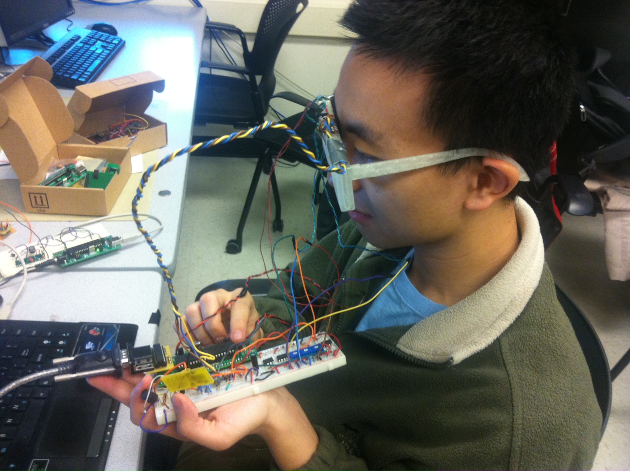
John using the Eye Mouse
High Level Design
Rationale:
After researching many eye-tracking devices, we realized that there was a lack of inexpensive and uninhibiting eye-tracking devices.
1. Cost - Most of the eye-trackers we researched used an infrared camera and signal processing software to track the reflection out of the pupil. These systems typically cost hundreds of dollars. Therefore, we decided to go with an infrared LEDs and phototransistors instead of a camera. This method is also much less intensive on our microcontroller than processing video.
2. Range of Motion - The eye-trackers we researched that did not use a camera were all used for medical applications, and as such, had the user lying down or putting their head into a mount. We wanted to make an eye tracker that did not resistrict motion of the head or neck. Consequently, we decided to mount our LEDs on a pair of glasses. This guarantees that the eye is always relative to the head.
3. Vision - Another consideration was how well the user could see using our device. This meant that we would most likely use a transparent lens. To further improve visibility, we would try to use as small components as possible (ideally, surface mount LEDs and phototransistors).
Logical Structure:
We have a pair of 3-D printed glasses with plastic lenses. These lenses have holes drilled into them to mount thru-hole infrared LEDs and phototransistors. The emitter is positioned above the eye and emits IR light, which is reflected off of the eye into the phototransistors below the eye. We also have a small gyroscope breakout board in the center of our glasses above the bridge, which will detect head movements in three axes of rotation. All of these glasses-mounted components are connected to a microcontroller, which parses the LED and gyroscope data into USART packets and transmits it wirelessly. The packets are read by a wireless receiver on a separate ATMega1284P board, which moves the mouse cursor using a Java program based on the information received. The block diagram below better describes our system:
System Block Diagram
Background Math:
The primary safety concern is with the radiation from the infrared LED damaging the user's eye tissue. We researched this very carefully and made sure to purchase IR LEDs with a low intensity and wide profile. Our chosen LED have a maximum radiant intensity of 2.1 mW/sr at 50 mA.
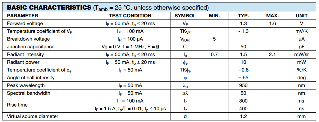
CQY36N Radiant Intensity
We are supplying these LEDs with 5.0 V/330 Ohms = 15.15 mA of current, which corresponds to a radiant intensity of roughly 0.4 mW/sr, as calculated from the plot below.
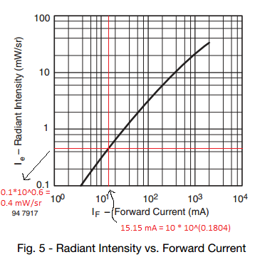
CQY36N Radiant Intensity vs Forward Current
According to the IR reflection hazards paper,
"In the case of full IR-A spectral band (700-1400 nm), the standard suggests that irradiance at or below 0.96 mW/cm^2 is safe for continuous exposure of a duration slightly greater than 8 hours. Through an analysis of this standard the authors will argue that the frequency cited corneal irradiance of 1 mW/cm^2 should continue to be recognized as a safe level of chronic ocular exposure to IR-A"
Seeing as how the maximum radiant incidence of the LTE4206 is 1.02 mW/cm^2, and the radiant intensity of our LEDs is much lower than the LTE4206 (0.4 mW/sr vs. 7.67 mW/sr), we can conclude that the radiant incidence of the CQY36N is also much lower than 1.02 mW/cm^2. Therefore, the CQY36N is safe.
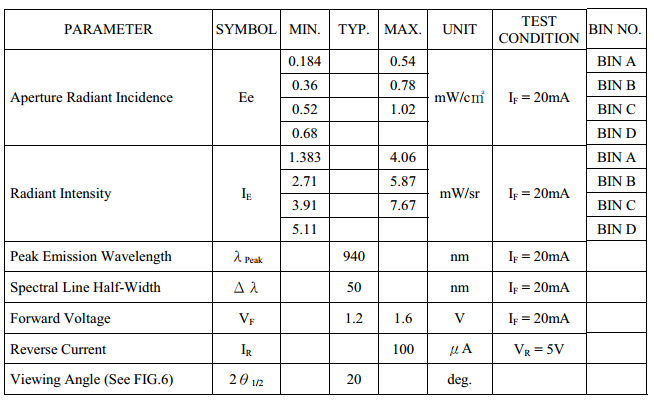
LTE4206 Radiant Intensity and Incidence
Hardware/Software Tradeoffs:
Unfiltered vs. Filtered Data
All of our data input came almost directly from the hardware sensors. After attempting to filter the eye signal, and after attempting to use a Schmitt trigger with hysteresis as an external ADC similar to lab 4, we decided the best method would instead to simply use raw data from the phototransistors. While we realized that we may need to go back and develop a better filter/amplification circuit, we chose to focus this project on the software/microcontroller design aspect rather than the pure hardware signals. Because we wanted to use wireless communication and a gyroscope in our project, we knew that debugging these communication channels and providing an interface with the microcontroller for collaboration between these separate inputs would still be a hefty technical challenge.
3-D Print vs. Safety Glasses
We chose to design and 3-D print our glasses in order to build a product. While we could have borrowed someone else’s glasses design or simply used a pair of safety glasses, we wanted the majority of the project to be design based, so we chose to build a pair of glasses using Solidworks.
Soldering onto PCB vs. Using a Protoboard
§ We chose to cut a PCB and solder a copy of our protoboard circuit onto it rather than simply use the protoboard. Having a final product as a goal, we wanted to make it easy for our future test subjects to wear the microcontroller on their head with the glasses.
Eyetracking Array vs. 2 phototransistors vs. 4 phototransistors
Our original plan was to use an array of phototransistors and LEDs to determine the eye location, but due to the difficulty with which this was to wire and test with, we decided to run tests using simply two phototransistors at first rather than to run tests with so much clutter. We attempted to use an array of phototransistors and LEDs before printing the glasses, and we realized that wiring and layout design would be a major difficulty in testing this sort of system. As such, we designed the hardware and software around 2 phototransistors hoping to improve on this design decision if time allowed. While we were testing our array design, we actually implemented a time based schedule for blinking each LED in the array.
Standards:
Please refer to the Safety section for our standards.
Existing Patents:
For intellectualy property considerations, we researched eye-tracking on Google Scholar and discovered a lot of work has been dedicated to this area. Particularly, a lot of the patents cite concerns for the integration of these systems to current applications. There are some hardware systems currently in development such as the “openEyes” project from Iowa State university , or the Real-Time eye detection project in the 2002 symposium on eye-tracking (Sources in appendix). We will be researching these projects in more detail to get ideas and to make sure that there will not be any additional legal issues with our design.
Hardware
1. Lens
The main purpose of our lens is to hold the infrared LEDs and phototransistors in front of the user's eye. To determine We first determined where our eyes were in relation to our glasses by securing a piece of acrylic we found in the lab to some cheap plastic frames we already had. Luckily, the plastic already holes in it for our LEDs, so we built a quick prototype and verified with a scope that the phototransistors operated as we expected it to.
The next step was obtaining acrylic and drilling some holes in it to fit our LEDs and phototransistors. We went to Lowes to get cheap acrylic and used a mill in the Emerson machine shop to drill an array of holes corresponding to the user's eye position.
2. Glasses
We designed our frames in Solidworks and 3-D printed them using a friend's Makerbot 2. This was a major portion of our mechanical design. Our major design considerations were the internal slots to hold the lenses, small troughs at the top to hold the wires from the infrared diodes, phototransistors, and gyroscope, and a slot in the center to hold the gyroscope.
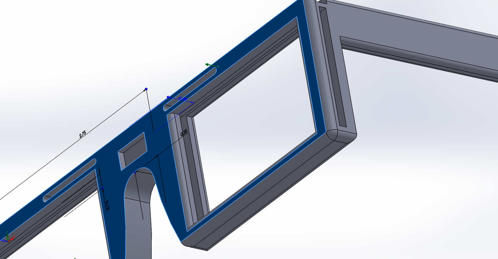
First Design
We printed the frame and the hinges separately because the hinges were too long for the Makerbot printer. After we printed the frame out, we realized that we needed to make all the slots wider; we severly underestimated the width of our plastic lens. Below is the second and final design for our glasses.
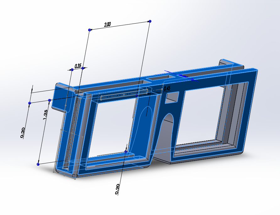
Final Design
In our second design, we made the glasses thicker (0.5 inches), made all the slots wider, and added hollowed extrusions on the sides for the hinges.
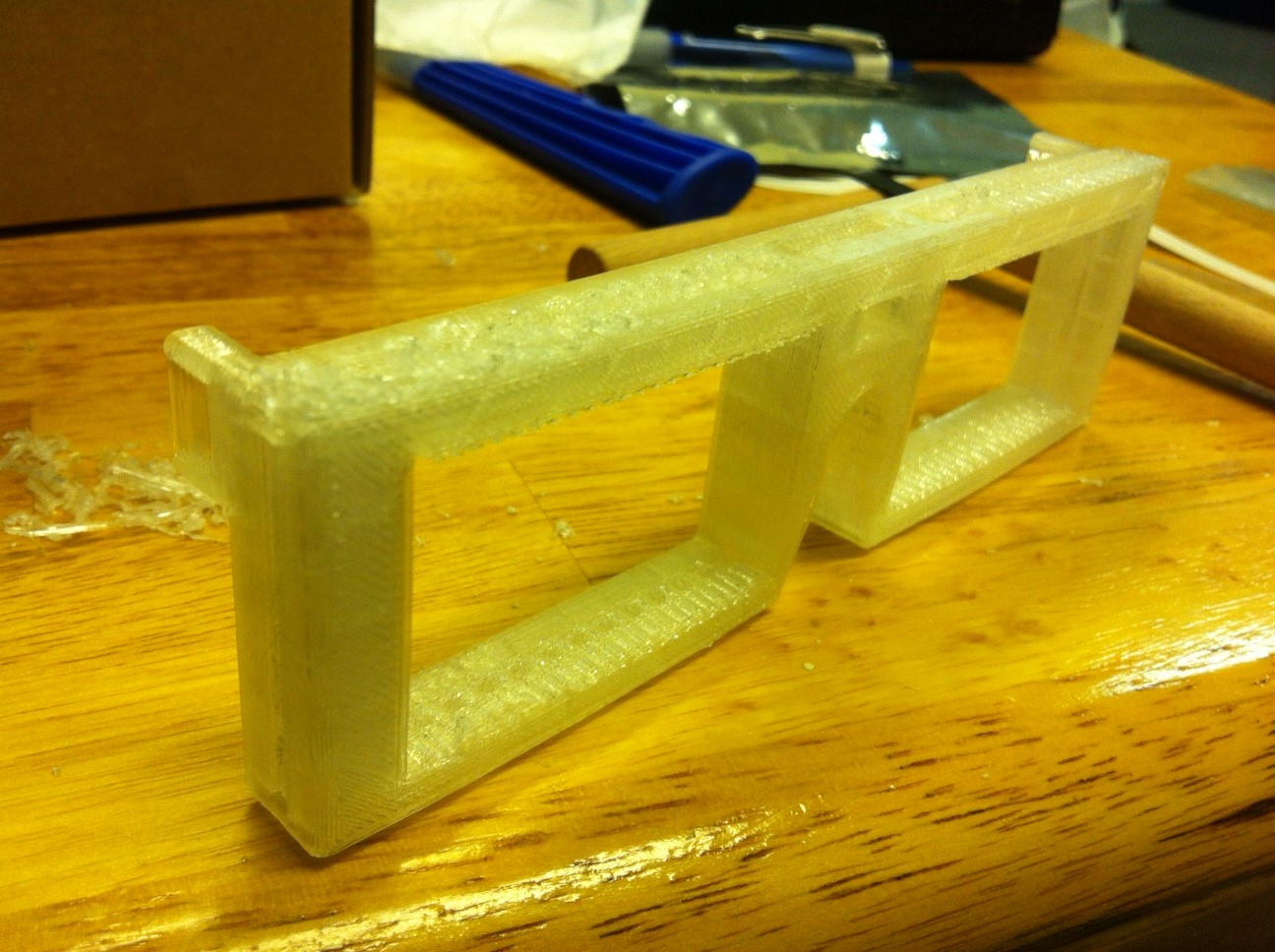
Physical Glasses
After we printed them, there was a lot of support material we had to remove from the various slots before we could insert our lenses.
3. Eye-tracking LEDs and Phototransistors
There are typically two configurations used when tracking eye position with infrared reflection. One configuration uses pairs of LEDs and phototransistors (Figure 3a)
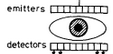
Figure 3a) Emitter-Detector Pairs
while the other configuration features a single LED to illuminate the eye and multiple phototransistors to receive the reflected signals.
Multiple Phototransistors
We used the configuration shown in Figure 3b) because the other configuration relies on the LEDs having a narrow beam profile to ensure that the light from one LED does not interfere with multiple phototransistors. The only LEDs we could find that had a narrow enough beam profile were the 5 mm LTE4206 LEDs in lab, which are too large for our design to have multiple fit across the span of our eye. We attempted to find 3 or 1.8 mm sized lensed LEDs with narrow beam profiles, but we could not find suitable ones. Therefore, we decided to purchase small, wide-angle LEDs for illuminating the entire eye. We ended up going with the CQY36N because of its almost spherical beam profile and small size (1.8mm).
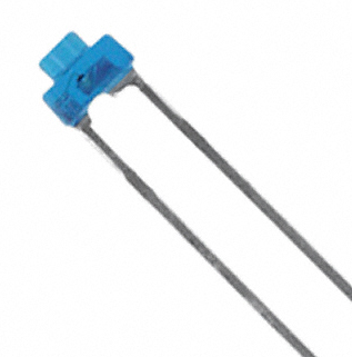
CQY36N Infrared LEDs
For our design, the phototransistors also had to have a sharp beam profile for good directional detection. Fortunately, the phototransistors available in lab, the LTR4208, are both small enough and have a narrow enough detection profile for our design.
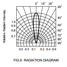
LTR4208 Radiation Pattern
4. Gyroscope
We used the ITG3200 gyroscope breakout board from Sparkfun Electronics. We decided to purchase this board because of its small size, 3-axis output, and ease of connection. The gyroscope uses the I2C interface to the microcontroller.
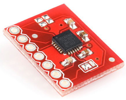
ITG Breakout Board
The hardware portion of the gyroscope was relatively simple. According to the Sparkfun hookup guide, we needed two pullup resistors for the SDA and SCL lines, a jumper connection between the CLK pin and the internal clock, and a 5-3.3 V regulator to power the gyroscope. Below are the schematics for this part.
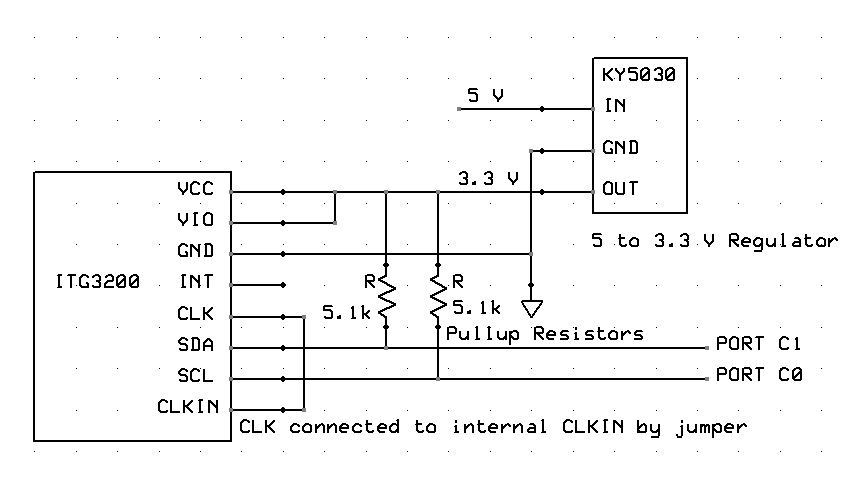
ITG Breakout Board
5. Wireless Transmitter and Receiver Circuits
Taking inspiration from previous groups, we used the Radiotronix RCT-433-AS transmitter and the Radiotronix RCR-433-RP receiver. We used Meghan Desai's transmitter and receiver libraries. We also took inspiration from the USB Wireless Tilt Mouse + Minesweeper project from Spring 2010 for the capacitor and inductor values used in these circuits.
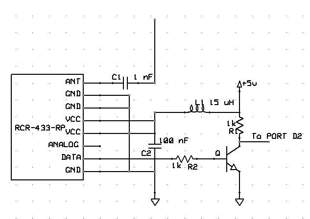
Receiver on the base station. Circuit taken from USB Wireless Tilt Mouse + Minesweeper Project
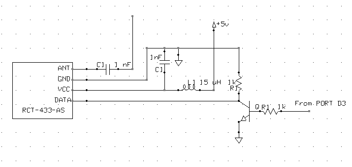
Transmitter. Circuit taken from USB Wireless Tilt Mouse + Minesweeper Project
The inductor-capacitor network is effectively a low-pass filter which smooths out voltage ripples from the power supply. The inductor in series with the 5 V supply attenuate high frequency voltage noise, while the capacitor bypasses this noise to ground. We could not find 10 uF inductors, so we used 15 uF inductors instead. The larger the inductor, the lower the cutoff frequency of this filter, so the 15 uH inductor should do better than the 10 uH inductor at smoothing.
The ANT pins are the transmitting and receiving antennas. We connected a long piece of wire to both, but the receiver picked up clean signals regardless of the presence of the transmitting antenna.
6. Custom PCBs
In an attempt to make our eye-tracking system more portable, we copied the transmitter circuit onto a copper PCB. However, while we could power this PCB, the transmitter was not working. There was a minor short from VCC to GND (using a multimeter, we measured a resistance of 2.9 kOhms), causing us to re-solder the VCC connections. After resoldering, we got a resistance of 3 MOhm, and the connection between VCC and GND no longer beeped, which meant the short was taken care of. However,the problem still persisted. We suspect it may have been a bad solder connection on a pin, but at that point, we decided to focus on the software and go with the breadboard setup because we knew that it had no hardware issues.
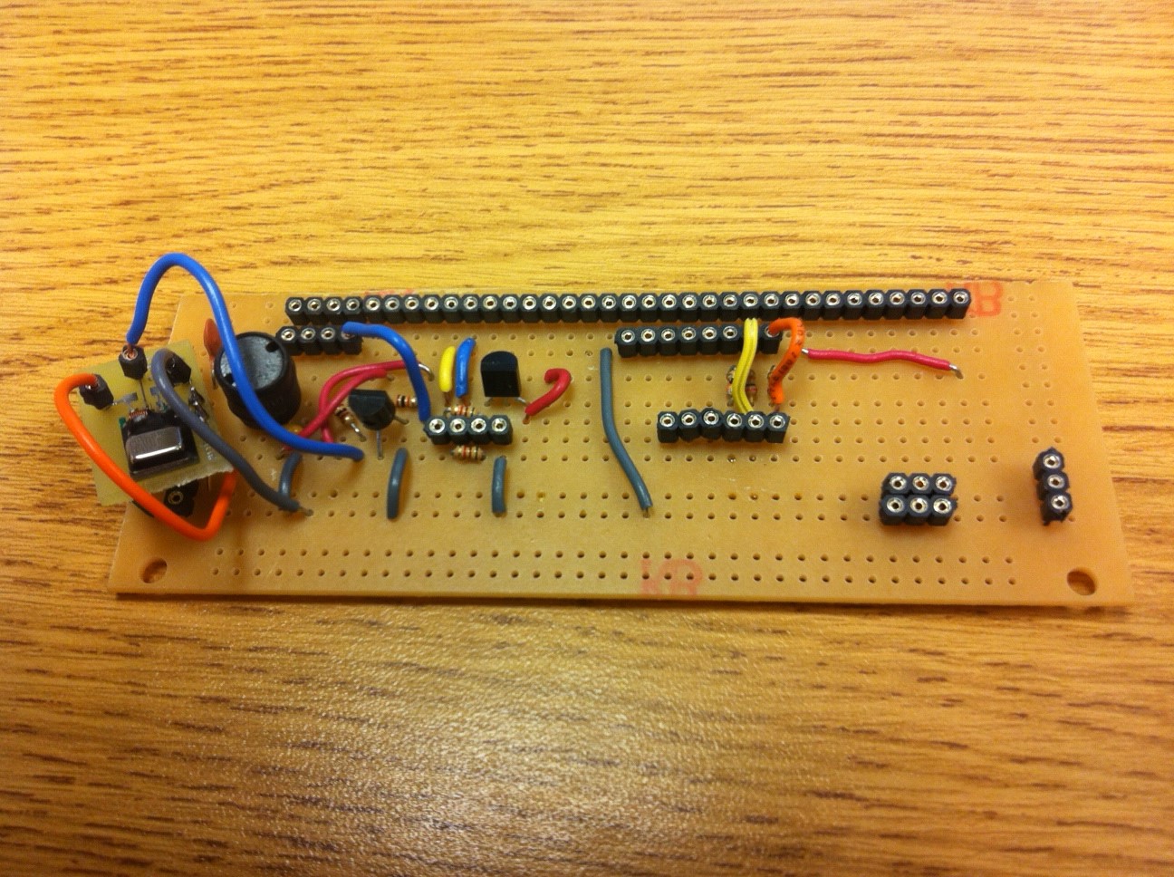
Transmitter PCB with Transmitter (on left)
We also soldered our own ATMega1284P microcontroller and serial communication module to use as a transmitter. However, the RS232 serial communication module did not work well when we tried to print to the screen. If we moved our heads too fast, the gyroscope would rapidly send data, causing the host computer to crash (BSoD). Fortunately, all of our code was saved in the Sublime Text 2 buffer, so we did not lose hours of work. Although this may seem unlikely, the BSoD happened 4 times before we stopped using the RS232 and switched back to serial output, at which point we did not encounter further BSoDs.
Another problem we encountered was burning the on-board regulator of the ATMega1284P. With Aadeetya and Roland's help, we desoldered the regulator by a combination of applying new soldering, using copper wicks, melting old solder using an iron and hot-air gun, and removing solder with the solder sucker. Thank you so much, Aadeetya and Roland. We could not have done it without their help.
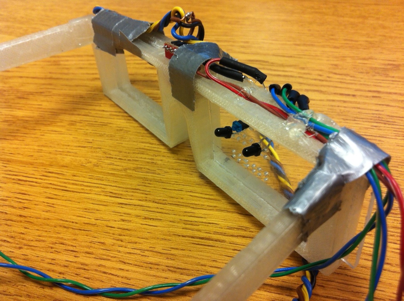
Final Hardware Setup
Software
A. Program Details:
We divided our software into three large components: our head-mounted transmitter code, the base station wireless receiver code, and the Java interface for Mouse control. We used Meghan Desai's code for the receiving and transmitting circuits.
Transmitter
The transmitter was the main station for extracting data from our phototransistors and our gyroscope. By interfacing between these distinct components, and wirelessly transmitting control signals to the base station, the transmitter code did the majority of the analytics and Master/Slave communication, to determine mouse movements for eye motion and/or gyro motion. These realized values were then transferred through the wireless communication channel.
We split the transmitter code into two sections: gyro and eye tracking. These two tasks were separated using TRT to manage the hardware. We actually implemented our own I2C transmission protocol (based upon what was supported by the Atmega1284p chip). This involved monitoring TWI registers and outputting the final data values from the slave gyro to the gyro task.
The eye tracking code was actually quite straightforward. We implemented the two ADC channels in software and used the ISR to context switch between reading values from each. This data was then averaged for every 10 samples to reduce noise. The averaged ADC readings were then combined with gyro data into a single packet and transmitted wirelessessly to the base station.
Receiver:
The receiver code focused upon data formatting and output through serial communication to a port on the computer. Using USART, we reformatted the wirelessly transmitted array of characters into proper values and printed them to the standard output.
Mouse Control:
The java code on the computer end took care of everything related to mouse movements. We used RXTX as our serial infrastructure to connect to the port from the receiver. Then, once these values were read in through an input stream, we made function calls to wrappers around Java’s Robot AWT class. This allowed us to interface with the mouse cleanly. We wrote functions to take care of mouse movement (up/down/left/right) taken from gyro control signals and eye tracking control signals. Similarly, we attempted to maintain a state machine for head gesture controls. This involved additional work on the back end to maintain a calibration state, a “Nodding” state, and a “Shaking” state for head gestures such as nodding, shaking, and tilting. We eventually scrapped this basic mechanism in favor of more direct input from the eyetracker. Our eyetracking system fed into the X-axis direction of the Mouse. In order to make the two phototransistor signals independent of distance to the eye, we used the positive or negative derivative of the signal to decide the direction in which the mouse should move. This speed that the mouse moved was a constant value based upon each packet received indicating a direction to move. A mouse click was mapped to tilting the head at the very end of the project.
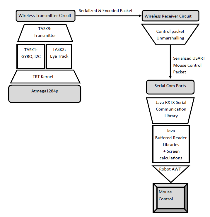
Software Flow Diagram
B. User interface
The gyro was used as the control for the y-axis, and the eye tracking was used as our x-axis control. We decided on this policy due to the intuitive ease with which a user could lift or lower his head and change the mouse. After testing the gyroscope, we were able to get very intuitive y-axis resolution with head nodding. Since we decided on a pair of phototransistors, we believed that eye tracking would at best used for x-axis resolution.
C. Abstraction layers
One of the difficulties with this project was having to decide the lines of abstraction within our software. Where did we want to have networking layer code? How did we want to interface between this layer and the application layer? In what step of the data transfer would we actually want to interpret these values and convert them into some sort of useful control signal for the mouse? At what step in the software abstraction would we even be able to have all of the pieces for correct mouse movement? These questions were quite ambiguous, and each decision we made along the way helped influence the next decision. We started by deciding to place most of our data interpretation at the data gathering/transceiver side of things. This let us build the network layer packet with simply the two interpreted phototransistor values and the gyro x, y, and z values. From here, the receiver then unpacked this data, and simply repackaged it for serial output to the STDOUT of our COM port which Java would read. Java could then cover the application level code by translating the control signals into a mouse movement for a particular screen resolution.
D. Mouse control speed
One of our goals was to implement the mouse such that the head motions could increase the speed with which the mouse moved in a particular direction. We felt that this would allow the user to have a more intuitive feel for our product. Because we were unable to implement this successfully due to the limitations of eye tracking with only two phototransistors (refer to commented out code in our appendix), we decided to use an acceleration based mouse movement.
E. Java vs. Matlab
We chose to use Java for our mouse control because it would allow us to control the mouse with a simple interface (Robot AWT). We found a simple serial communication interface (RXTX), and we were eventually able to transfer packets smoothly into Java.
Results
Usability
A user could wear our glasses, look at various positions on a computer screen, and the mouse cursor would move left or right based on the coordinates at the center of the screen which are used as a reference (as described in the Software section). In addition, the user could tilt his or her head up and down, and the cursor would also follow the motion of the head depending on the speed at which the user moved his or her head. However, we could not get both features working simultaneously; when we had the LED eye-tracking output accurate, our gyroscope tracking was not usable, and when we had the gyroscope working, the results from our eye-tracking were skewed to the left.
We could have also increased the user's comfort by refining the mechanical design of our frames. The bridge was too small, so the edges cut into the nose during operation. In addition, the straight hinges were sometimes uncomfortable because the head would get in the way while putting the glasses on. Finally, the frames were thick and therefore heavy. A future design would make the glasses thinner while still maintaining enough room for the lenses to fit, enlarge the bridge, and refine the shape of the hinges to be more curved to take into account the shape of the user's head.
Accuracy
The system was moderately accurate with regards to LED x-axis sensing and head tilt detection, and further improvements could be made. We could implement an algorithm that tells the cursor to stop moving if the user's eye stops moving, split up the screen into more sections and sample with greater frequency to get smoother cursor movement, and make clicking more functional.
Safety
As described in the Background Math section, we have adhered to the safety standards described in the ANSI Z136.1 standards. There are many factors we need to consider. Some safety considerations relating to human usage include the radiation injected into the head using the infrared LEDs, the durability of the glasses that hold the eye-tracking device. and the reflection of the focusing lens back into the eye. In addition, we want to consider the usability, human factors, and the human interface. We need to make the system comfortable and safe. We will also need the system to be able to detect where the person is looking and output on a separate screen which the person will be able to look at. Most likely, someone else will need to read the output and reference it with where the other person is actually looking during testing/calibration. In terms of people with special needs, such as blind people will not be able to use our system, but hopefully, deaf people would be able to use our system to better communicate what they’re looking at with others.
Optical Radiation Safety Guidelines and Standards
The most prominent organizations that have recommendations with regards to optical radiation exposure limits for the eye and skin are the ACGIH (American Conference and Governmental Industrial Hygienists) and the ICNIRP (International Commission for Non-Ionizing Radiation Protection). The guidelines recommend a maximal daily corneal exposure of 10mW/cm^2 total irradiance for IR wavelengths for all-day exposure (t > 1000s). In fact, the “infrared radiation hazard limit” set by ANSI/IESNA and CIE/IEC for lamp safety was 1.0mW/cm^2. We note that higher irradiances are permitted for exposure durations less than the 1000s. For example, a single 800 microsecond pulse can be up to 210W/cm^2. In terms of retinal injury thresholds, most eyetrackers do not even come close to reaching the maximum pemissible exposure limits.
Difficulties
One of our major problems was integrating the many different systems and components together. Without this integration, we had limited ability to test out “Eyetracking”. In particular, without a frame, we could not build a systematic way to test our two phototransistor system. Additional hardware problems included incorrectly soldered boards leading to BSODs and shorts (burned regulators). Software problems involved stabilizing the eyetracking signals to be distance independent, dealing with many different codebases on many different computers and microcontrollers.
Conclusions
Final Design Analysis
Our overall project met our most basic expectations. We were able to get some mouse sensitivity (on the x-axis) based upon our eye movements. At one point, we could shift our eyes, and the mouse would simply follow along on the screen. Similarly, any head movement (up or down) would lead to the mouse following in that direction as well. While in our demo, we were unable to show the full impact of our eye movements causing the mouse to move, this was meeting our expectations at an earlier point in time. Our most basic expectations were to get the eyetracking circuit sensitive to our eyes, and to get a wireless system working such that a 3-D pair of glasses with LEDs on it could be worn by a user. We felt that this was highly successful.
There are many things we would like to differently for next time. In particular, we would want to iterate on our LED/phototransistor design more such that we could get a more accurate sensor reading. Similarly, now that we have had more soldering experience, we would probably not have as many of the hardware errors as we had beforehand. Thus, we want to resolder some of the hardware PCBs that we built. In terms of actual eyetracking, we would love to do some testing on a variety of different people because this will allow us to take better data and understand what kind of eyetracking system (UI) people would actually use. From the tradeoffs section, we listed some further improvements we would like to do if we had time, and luckily, Bruce is willing to do an Independent study with us which we believe will help us bring this project to the fully completed state.
Applicable Standards
We adbide by the ANSI C Language standards and the 1666-2011 IEEE Standard System Language.
Intellectual Property
The entire hardware design of this project was done without referencing any other designs or the intellectual property of others. The software we wrote is also mostly of our own design, although we did utilize ideas learned from Bruce Land's example code from the previous labs, we did not explicitly copy any of those programs. We did use the UART.c and UART.h files, which are under the "Beer-Ware License" and were written by JoergWunsch.The patents listed previously are only related to our project and we did not directly use any of the ideas claimed within them. We did not reverse-engineer a design, so there should be no patent or trademark issues.
Ethical Considerations
We have complied with the IEEE Code of Ethics throughout this project. During the design and construction of our project, we were careful to make decisions consistent with the safety, health, and welfare of the public. For instance, when drilling holes through our plastic lenses with a power drill, we made sure to use clamps to secure the lenses and scrap wood to stop the drill bit, ensuring our own safety and the safety of others around us. We also wrapped heat shrink around the exposed wires coming out of our LEDs and phototransistors to minimize the risk of ESD damaging our board.
We also assisted our colleagues and co-workers in their professional development by giving help whenever they requested. For instance, we suggested soldering tips when fellow groups were having trouble soldering the ATMega1284P breakout board, since we both have experience doing so.
One of the major ethical considerations we considered was what would happen if someone were to lose their vision if they used our system for too long. That is why throughout our project, we have been trying to reduce the radiation on our eyes. We looked into lower voltage and lower radiation LEDs as well as timer based arrays of LEDs that would help reduce overall intensity. We believe that the system at this point is as safe as possible with an IR Led design. This means that in terms of designer ethics, we believe we have covered our basis. We will obviously want to warn users of the radiation towards their eyes before any further testing or selling of this product.
Legal Considerations
As far as we know there are no legal restrictions on our project. The project hardware did not include any transmitter and as far as we know does not interfere with the operation of other electrical equipment.
Appendices
A. Commented Code Listings
B. Schematics
C. Budget Considerations
| Parts | Quantity | Unit Cost | Total Cost | Source |
| ITG3200 Gyroscope Breakout Board | 1 | $19.95 | $19.95 | Sparkfun |
| ATMega1284P Breakout Boards | 2 | $5 | $10.00 | Lab |
| Power Supply | 1 | $5 | $5.00 | Lab |
| 9V Battery | 1 | $2.00 | $2.00 | 7/11 |
| RCR-433-RP Receiver | 1 | $4.00 | $4.00 | Lab |
| RCT-433-AS Transmitter | 1 | $4.00 | $4.00 | Lab |
| Glasses | 1 | Free | Free | Makerbot |
| CQY36N Infrared LEDs | 10 | $0.52 | $5.52 | Digikey |
| Wires, Resistors, Caps, Inductors, phototransistors, PCB components, connector cables, etc. | Many | Free | Free | Lab |
Total Cost: $50.47
D. Task Division
Michael |
Both |
John |
Gyroscope code |
Testing/Debugging |
Mechanical measurements |
Mouse Code |
Circuit Design |
Glasses design and printing |
Transmitter/Receiver Code |
Research |
Soldering test PCB, RS232 chip, and extra ATMega1284P breakout |
Project concept |
||
Web Site |
References
A. Vendor Sites
B. Code/Designs Borrowed from Others
We used Meghan Desai's Wireless Transmit and Receive Project, including the receiver and transmitter he suggested. We also used the receiver and transmitter circuits from the USB Wireless Tilt Mouse + Minesweeper project (however, we created new schematics from their circuits). Finally, we took inspiration from the Optical Eye Tracking project with regard to the main application we were doing.
C. Background sites/Papers
Safety
IR reflection hazards paper
Intersil Application Note
Hardware
Research Papers
A Two Dimensional Fiber Optic Eye Position Sensor For Tracking and Point-Of-Gaze Measurements
D.C. Johnson, D.M. Drouin, and A.D. Drake. 1988.
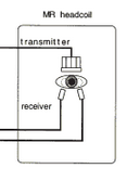
MR-Eyetracker: A New Method for Eye Movement Recording in Functional Magnetic Resonance Imaging.
H. Kimmig, M.W. Greenlee, F. Huethe, T. Mergner. 1999.
Precise recording of Eye Movement: the IRIS Technique, Part 1.
J.P.H Reulen, J.T. Marcus, D.Koops, F.R. de Vries, G. Teisings, K. Boshuizen, J.E. Bos. 1988.
Precise recording of Eye Movement: the IRIS Technique, Part 2.
J.P.H Reulen, J.T. Marcus, D.Koops, F.R. de Vries, G. Teisings, K. Boshuizen, J.E. Bos. 1988.
Inspiration
USB Wireless Tilt Mouse + Minesweeper
Wireless Transmit and Receive Project
Optical Eye Tracking
Image Scan using Phototransistor Array
Easy Input
Acknowledgements
We would like to thank:
- Bruce, Roland, Aadeetya, and all the TAs for all their time spent helping us with our project.
- John Chong for letting us sample the KX022, Kionix's most recent accelerometer.
- Professor Drake for his willingness to help us understand the eye-tracking project he worked on and J.E. Bos for granting us access to his research paper on eye-tracking.
- The guys at the Emerson lab for helping us with the construction of the plastic lenses.
- Meghan Desai for writing the wireless receiver and transmitter protocol.