Disclaimer: This device is a prototype/student project. It is not guaranteed to prevent any dangerous fires.
Introduction top
We have created an autonomous, servo-controlled fire extinguisher that is capable of aiming photo sensors and a water nozzle along two axes to detect and extinguish candle fires a short distance (about 1 ft.) away using a small burst of water.
Our inspiration originally came from thinking about an automated toy sentry turret that could fire at intruders (like a NERF® gun), but given ECE 4760’s ban on weapons and projectiles we thought that project was unsuitable. Additionally, we wanted to create something that might actually be useful. So, considering that current indoor fire prevention systems (such as ceiling sprinklers) can cause excessive damage by spraying everything in the room upon a whiff of smoke, we took the NERF® turret idea and turned it into a smarter fire mitigation system that sprays water only at fires. Of course, since our potential users (eg., home owners) would most likely not be around when our fire-extinguishing sentry’s vigilance would be most helpful, our system had to be autonomous. We thought that driving an autonomous system like this one would be a good application of the microcontrollers topics we learned in ECE 4760.
Although what we have actually built serves only as a proof-of-concept, we think that a device operating on similar principles could be useful both indoors and outdoors as a smart, home fire prevention system or a forest fire mitigation system, respectively.
High-Level Design top
The system has three major actuators: a water pump that sends a burst of water from a nozzle up to a few feet away, a servo motor that controls the horizontal position (angle) of the water nozzle, and a servo motor that controls the vertical position (angle) of the water nozzle. We use an ATmega1284p microcontroller (MCU) to manage both the “on” signal sent to the water pump and the positioning signals sent to the servos.
In order to detect fires, our system employs three major sensors: a central sensor that sees directly in front of the device approximately where the water nozzle is aiming, a sensor that sees diagonally upward from the approximate location of the water nozzle, and a sensor that sees diagonally downward from the approximate location of the water nozzle. We adjust for defects in the mechanical positioning of our sensors via software offsets. The upper and lower sensors are sensitive to visible light, and consequently they detect more than just fires. The center sensor, which is sensitive to infrared (IR) light, is activated more specifically by fires; consequently, it has the final say in whether a threat picked up by any of the sensors should be extinguished. The sensors all have their horizontal field of views (FOV) restricted so that we can think of our sensor array as analyzing a single patch of vertical space at a fixed horizontal position. The center sensor also has its vertical field of view restricted. The idea is that by sweeping the sensors along a horizontal axis, the center sensor will see only the point where the water nozzle is directed, while the upper and lower sensors can alert it to any other points that the system might want to check out with the center sensor. While scanning, if our system detects something via its center sensor, it immediately considers it a fire and activates a brief spraying routine to extinguish it. If it instead detects something via its upper or lower sensors, it pauses its horizontal scanning routine and begins sweeping the water nozzle (and the collinear center sensor) vertically in the direction of the activated sensor(s), giving priority to the upper sensor. By passing the center sensor over the source, our system can determine whether it is actually a threat and initiate an appropriate response (spray the source with water or ignore it). When the vertical scanning routine is done, the system resumes its horizontal scanning routine and the process repeats. Figure 1 (below) illustrates the basic operation of our system:
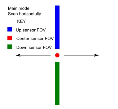
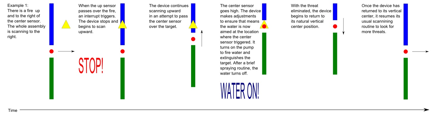
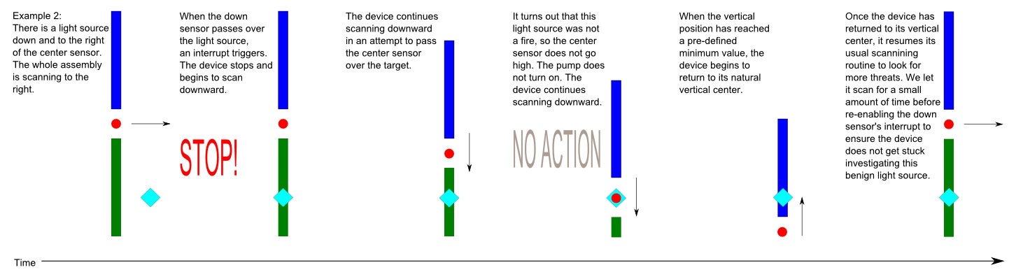
Figure 1: The above figure depicts our high-level approach for detecting and extinguishing fires.
Although the cases depicted above are not exhaustive, they readily extend to cover many analogous scenarios. Even though we only show the upper sensor detecting a real threat and the lower sensor detecting a false alarm, both sensors possess the same capabilities for processing threats (in fact, the sensors are identical except for their positioning). Furthermore, our system behaves in much the same way scanning left horizontally as it does when scanning right horizontally (as shown in Figure 1). Note that if the center sensor triggers during a horizontal scan at the resting vertical position, the system can and will respond to the threat immediately without initiating the vertical scanning routines described in Figure 1.
Hardware Design top
Our system is composed of the following major hardware components: the system itself, which is composed of wood, aluminum, and an old bottle serving as a water reservoir; two Futaba S3004 servos that aim the water nozzle and its accompanying sensors; a pump salvaged from a windshield washer; and two 12 V power supplies, one of which is rated for 1 A (to drive the MCU board, most of our circuitry, and our servos), and another rated for 5 A, which drives the pump. Refer to Figures 2 & 3 below for a close-up of our system and its circuitry.
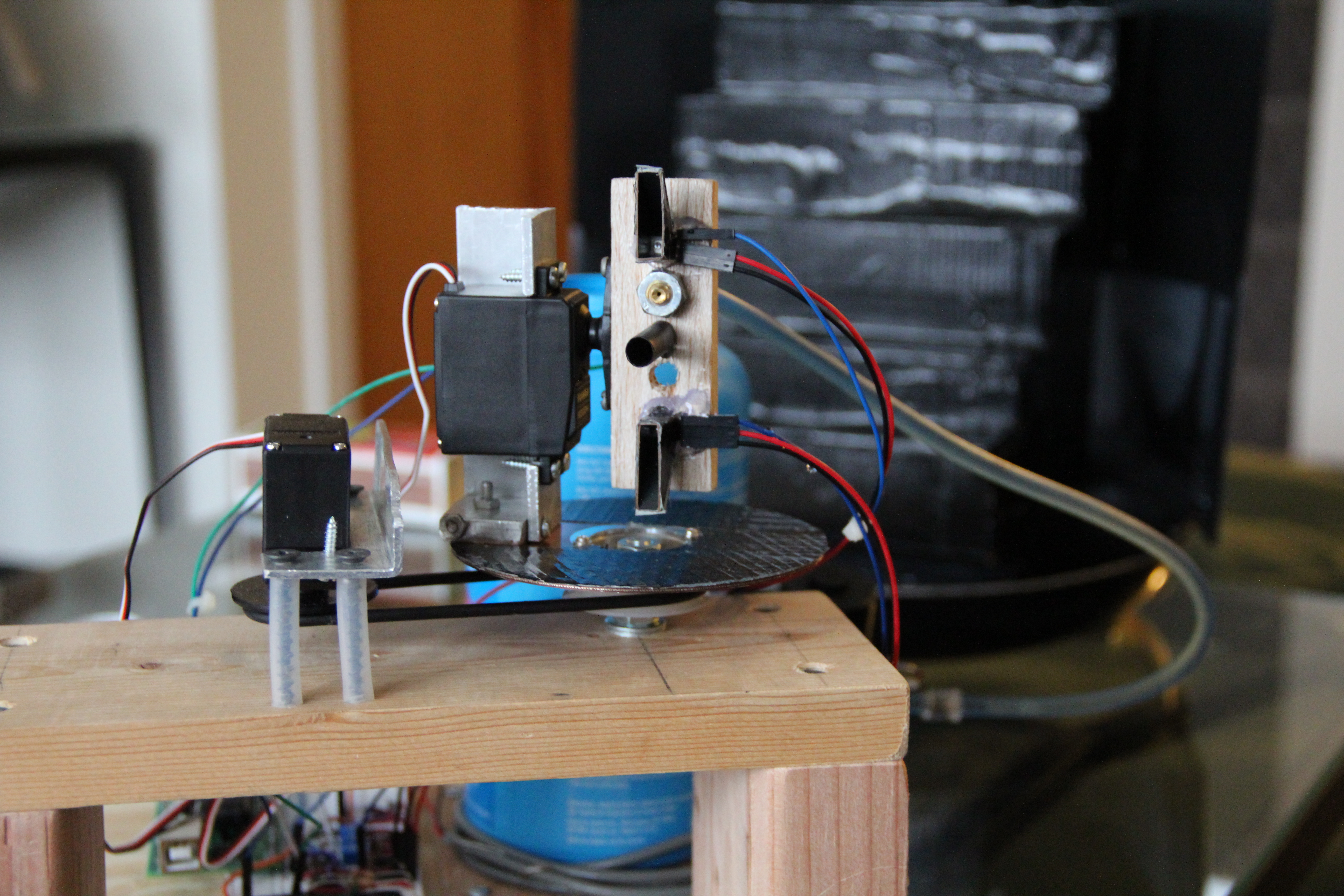
Figure 2: Above is a close-up of our automated fire extinguisher. The rotating assembly is elevated above the level of the pump and water reservoir to prevent water leakage in the idle state. From top to bottom, we see the up sensor, the water nozzle, the central sensor, a hole drilled in preparation for a Melexis MLX90614 IR thermometer (which we did not end up using), and the down sensor.
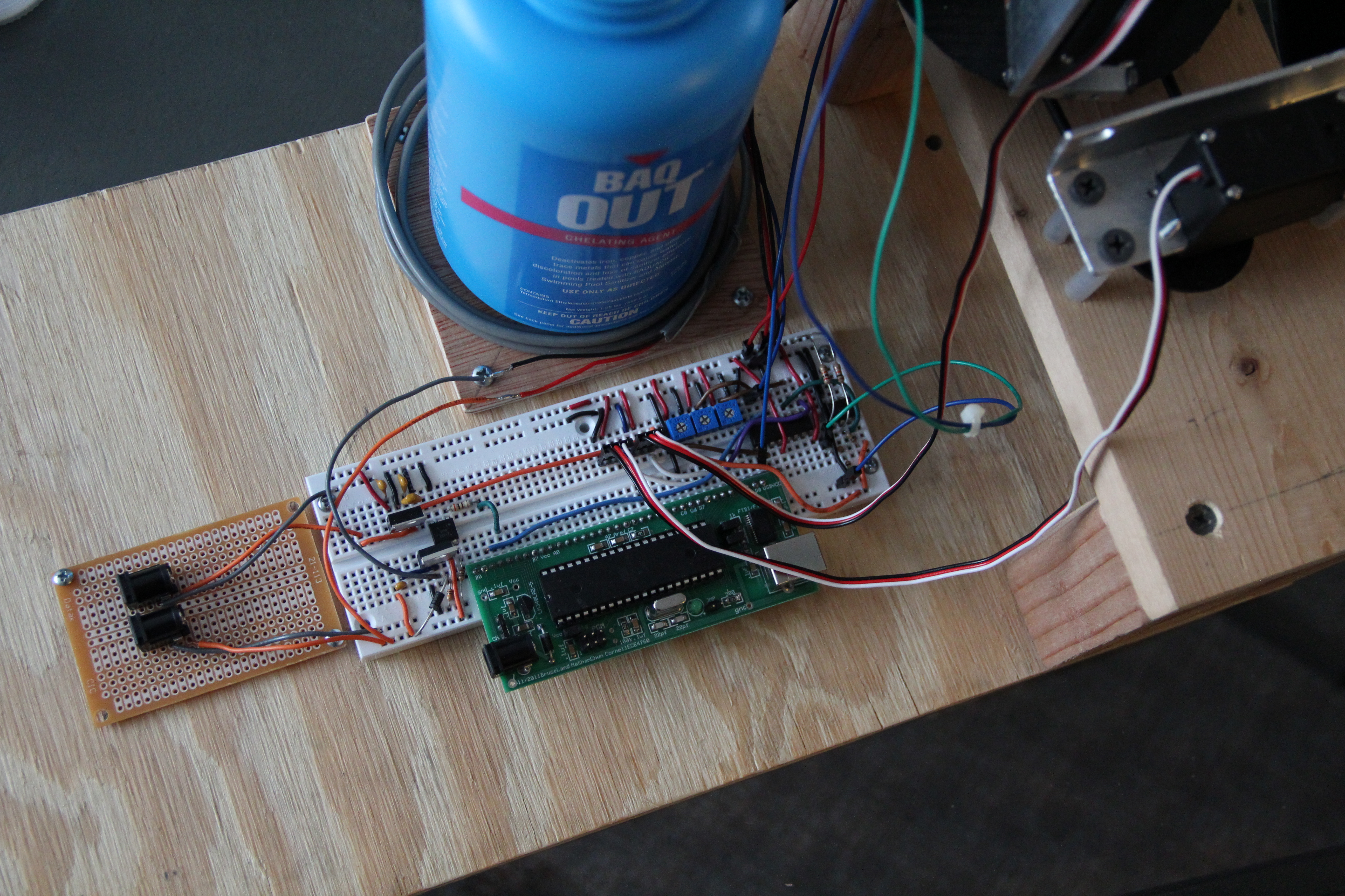
Figure 3: Above is a close-up shot of our system’s circuitry. The USART on the microcontroller is used only for debugging.
Our system’s circuitry consists of four major subsystems: the servo subsystem, which consists of direct connections to two of the microcontroller’s PWM output pins; the sensor subsystem, which consists of three op-amp collections that convert readings from three separate phototransistors into digital inputs to our microcontroller’s interrupt ports; a power system, which allows us to have both 12 V and 5 V rails; and our pump control circuit, which consists of an opto-isolator and a separate 12 V supply. In the sections that follow, we will take a detailed look at each of these subsystems.
Servo Subsystem1
Each of our servo motors has three connections: one for ground, one for power (5-6 V), and one for a control signal. In our system, both of the servos run at 5 V.
Servos expect their control signals to arrive in a pulse-width-modulated (PWM) form. Most servos, including those upon which our system relies, respond best to PWM control signals produced at 50 Hz. Although at 50 Hz, new control pulses should arrive every 20 ms, the uptime of a typical servo control signal is very small (on the order of 1 ms) compared to the period of the entire signal. In other words, servo control signals have a low duty cycle. Still, it is by varying the duty cycle of a servo’s control signal that one commands it to change its position. Internally, a servo uses a potentiometer to determine its position. The command for neutral typically involves setting the control signal for the servo in question to have an uptime of around 1.5 ms every 20 ms. This control signal corresponds to the point where the servo’s internal potentiometer is exactly balanced with respect to its clockwise and counter-clockwise potentials. Typical control signals for sending a servo to its farthest counter-clockwise position have an uptime of around 1 ms, and typical control signals for sending a servo to its farthest clockwise position have an uptime of around 2 ms.
For our purposes, it wasn’t necessary that either of our servos rotate to the poles of the full 180° spans they support. Nevertheless, we calibrated each of our servos so that they could sweep suitable areas in front of our device (approximately 150° of horizontal rotation and 70° of vertical rotation). We determined the following pulse widths for our particular servos:
Table 1: Below are the pulse widths for the command signals we empirically determined in order to send our system’s servos to the listed positions.
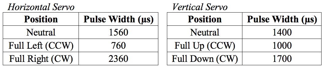
As you can see, the necessary pulse widths for driving our particular servos were close to the values typically listed, but some degree of empirical calibration was required. In order to produce two consistent PWM pulses without wasting CPU time, we made use of the ATmega1284p’s onboard 16-bit hardware timer (Timer 1), and operated it in fast-PWM mode. In this mode, Timer 1 can be used to generate two separate PWM signals on the microcontroller’s output pins D.4 and D.5, with PWM duty cycles governed by the 16-bit output compare registers OCR1A and OCR1B, respectively. We drove our system’s horizontal servo off pin D.4 and our system’s vertical servo off pin D.5.
Servo motors are a cost-effective means of achieving precise positioning with a microcontroller. And, given the background information above, interfacing with them is fairly straightforward. However, they have one significant drawback: they provide no feedback about their current position. That means once one has sent a command to a servo motor, one has no way of knowing exactly when the servo will have finished responding to that command. For our application, it is essential that our system is able to stop both servos whenever it detects a threat. However, servos only take a destination as a command. Thus, in order to “stop” a servo, one must send it a command to go exactly where it currently is, without any way of obtaining that information from the servo itself.
We experimented with two approaches to tracking our servos’ positions so that we could send them precise “stop” commands. Our first approach involved using a hardware timer on the ATmega1284p (Timer 2) to time the interval since the last command had been sent to either servo (our system only activates one servo at a time). Using information about the servos’ rotation speeds from their manufacturer, we were able to multiply the travel time we measured by a constant conversion factor to estimate the servos’ positions. Under this approach, the only commands we ever sent to either servo were commands to move to the left/right or up/down poles listed in Table 1 above. Unfortunately, the servos shifted between the poles in a non-linear fashion, so tracking them precisely was impossible with just a single proportional constant. We were able to achieve much more consistent performance with a different approach, which is the approach our system still uses. After sending each servo an initial positioning command and waiting to be sure the servos are starting from these initial positions, we increment or decrement (depending on the direction of travel) the registers governing the servos’ PWM control signals by one at a time, with a small delay (8 ms) between each subsequent command to allow the servos time to finish travelling. In this way, our system is constantly keeping track of each servo’s position, within ± 1 output compare register units. In our system, Timer 1 runs at (16 MHz)/(64 prescalar) = 250 kHz, which gives us 4 µs between each subsequent timer count. That means we have (2360 µs — 760 µs)/(4 µs) = 400 possible horizontal positions and (1700 µs — 1000 µs)/(4 µs) = 175 possible vertical positions, according to the command signals listed above in Table 1. Following these calculations, our second approach has a horizontal positioning error of ±(1/400) = 0.25% and a vertical positioning error of ±(1/175) = 0.57%.
Sensor Subsystem
As mentioned above, our system employs three major sensors: a central sensor, an upward sensor, and a downward sensor. The central sensor is an infrared phototransistor most sensitive to light in the 940 nm range, while the upper and lower sensors are identical phototransistors highly sensitive to visible light from 600 nm to 900 nm (approaching the IR range). The most important design consideration for the center sensor was that it be specific enough to distinguish fires from other light sources that could be false alarms, and the most important design consideration for the upper and lower sensors was that they possess a wide field of view. We would have preferred to use IR sensors for the upper and lower sensors to avoid false alarms caused by regular light sources, but it was important that we embedded as few sensors as possible in our system’s rotating assembly to cut back on the amount of wiring that our servos had to move (and potentially pull loose). To compete with the naturally wide field of view of the phototransistors we selected for the upper and lower sensors, we probably would have needed to use small clusters of IR phototransistors at slightly different angles.
Another important design consideration for our sensors was that they needed to detect targets at least a foot away in order for our prototype system to be an effective proof of concept. The upper and lower sensors were TSL12S phototransistors that included integrated amplifiers, but we needed to amplify the signal produced by our system’s central sensor (an LTR-3208E) since it was otherwise weak beyond 6 inches away. We also inverted and offset the signal coming from the central sensor so that all of sensors produced rising, positive voltages upon detection. Before connecting the sensors to our microcontroller, we digitize their outputs using three simple comparator circuits with variable thresholds set by 10 kΩ potentiometers at their negative terminals. Our comparator circuits do not employ any hysteresis because our testing revealed it was unnecessary and even undesirable. Once made digital, each sensor’s output is fed to one of the ATmega1284p’s external interrupt pins (D.2 for INT0, D.3 for INT1, and B.2 for INT2). The manner in which we make use of these signals will be described in the software section below. For now, refer to Figure 4 below for schematics of our sensors’ amplification and thresholding circuits:
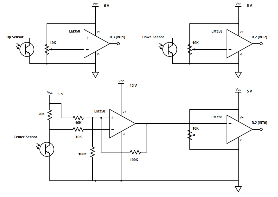
Figure 4: Above is a schematic for the circuits that convert our sensor signals into digital readings on the microcontroller’s interrupt pins.
Power Subsystem
Our system is powered by two separate 12 V power supplies. One of them, rated for 1 A, is used to power the board containing our ATmega1284p, our servos, sensors, and op-amps. The board we use for the ATmega1284p2 takes 12 V off a splitter from this power supply. The rest of the circuitry runs at 5 V, however, so we use an LM7805 voltage regulator to bring the voltage down to a suitable level. Although our microcontroller board has a built-in 5 V output, it is limited to 100 mA by an internal regulator, which is not enough to power our servos (they can demand close to 1 A when running at their maximum speeds). Figure 5 below shows a schematic of our voltage regulator circuit, which includes the input and output capacitors recommend in the LM7805 datasheet:
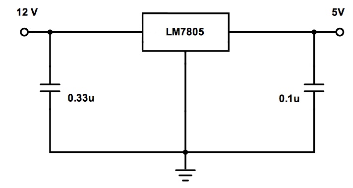
Figure 5: The above schematic shows the voltage regulator we use to step the 12 V, 1 A PSU down to 5 V to power the servos and other circuitry. The 5 V output after the microcontroller board’s built-in voltage regulator has a maximum current of 100 mA, which is not sufficient to drive the servos. In brief spurts, the servos can demand as much as 1 A.
Our second 12 V power supply, rated for 5 A, is optically isolated from the rest of our system’s circuitry and used to power its water pump.
Pump Subsystem
As mentioned above, our pump subsystem is optically isolated from the rest of our system’s circuitry. Motors like the one in our pump are typically noisy, high-current (ours takes around 3.5 A), and likely to produce large voltage spikes when turning on or off rapidly. Using optical isolation allows us to protect the rest of our circuit from any unintended side-effects of the motor control circuit. Figure 6 below shows the circuit we used to implement the control for our pump’s motor:
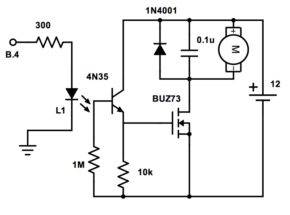
Figure 6: Above is our optically-isolated motor control circuit. The design is the same as the design we used in ECE 4760 Lab 43.We turn the pump on/off by driving B.4 high/low.
The circuit above is capable of safely handling rapid on/off transitions at the position of the motor in case we want to drive the pump with a PWM signal, which would allow us to effectively power the motor at a fraction of its full “on” voltage determined by the duty cycle of the PWM signal. For our purposes, explicitly setting the drive signal high for around 1.5 seconds during each spraying routine made more sense than using a PWM signal. In any case, the pump’s control signal is produced by our ATmega1284p’s B.4 output pin and gets transferred through the optically-isolated portion of the circuit (the 4N35 integrated circuit) to turn the transistor labeled “BUZ73,” which is acting like a digital switch, on or off. When the control signal transitions from low to high, the transistor turns on, allowing current to flow downward through the motor (it does not go through the safety diode since it is reverse-biased in that scenario). The induced current in the motor opposes the increase in downward current by flowing upward, but its magnitude is not large enough to do much to the downward current through the motor in the pump. When the control signal transitions from high to low, however, the transistor suddenly turns off, creating an open circuit and removing the connection of the pump to ground. The voltage across an inductor, which the models how the pump motor behaves, is given by V = L×(di/dt). Since the current rapidly drops to zero, di/dt suddenly becomes very large and the voltage across the motor spikes, trying to keep the downward current that just got shut off going. Without the safety diode in place, it would have nowhere to go due to the transistor being open; however, the voltage would be high enough to create a dangerous arc across the open transistor. This potential for arcing if the circuit is implemented incorrectly is one reason to use optical isolation, just to ensure safety.
Software Design top
Our software consists of two hardware timer routines, an external interrupt service routine (ISR) for each of our system’s three sensors, and a main control loop. The specific register settings that initialize the timer routines, ISR’s, and our hardware ports are most clearly and concisely explained in our commented code (specifically, refer to the initialize() function), which we have linked in the Appendix at the end of this page. This section will provide a functional overview of our software design. Note that, although we used USART to print debugging information to a PuTTY terminal, it is not essential to any of our system's functionality.
The first hardware timer, Timer 0, is used to establish a 1 ms time base for several parts of our system that rely on real-time delays. For the most part, this 1 ms time base is used to give our system’s servos time to sync up their actual positions with their command signals. It is also used to control the timing for enabling/disabling our system’s pump, as well as the timing of state transitions in our water-spraying state machine. Finally, it is indirectly used to delay the re-enabling of our sensor interrupts for a small time (actually a discrete number of time-delayed servo movements) after they initiate the handling of a suspicious event since it is otherwise possible that our device could get stuck continually investigating a non-extinguished source, like a false alarm. The second hardware timer, Timer 1, is used to generate the PWM control signals for the servos that aim our device’s water nozzle and sensor assembly. Once set, the control signals are continually produced until updated; doing so ensures that the servos hold their positions and that they are unaffected by noise.
We use a separate external interrupt service routine for each of our three sensors (INT0, INT1, and INT2). Using full-fledged external interrupts instead of pin change interrupts (which the ATmega1284p also supports), allows us to specify the edge upon which they fire (we use positive edge triggers), as well as identify which of them has fired. Depending on which of the sensors has triggered an interrupt, we apply some offsets related to empirically determined properties of the sensor in question and stop the servo that was last scanning. All the of the interrupts then feed into a state in the state machine that our main control loop executes, STATE_SENSOR_CHECK, which examines which of the other sensors might be high given the device’s current orientation in order to determine an appropriate next action. When one of the sensor interrupts fires, we temporarily disable it from firing again until our state machine has finished processing it. Because we have halted all system movement at the point of this processing, our timing requirements are pretty relaxed.
As alluded to above, the main control loop executes a state machine based on a few timing conditions set by Timer 0 and a major state transition governed by the external interrupts. The state machine we use is essentially a detailed, implementation-specific version of the high-level approach we described above in High Level Design. Since state machines are best explained visually, Figure 7 below depicts the one that governs our device’s operation (a more detailed look at a minor state machine internal to the major one below is included in Figure 8):
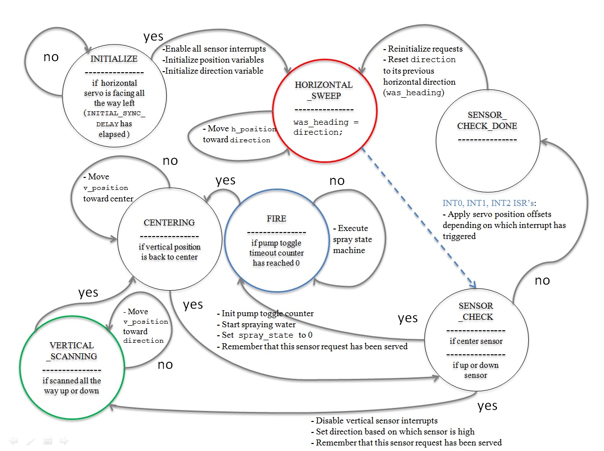
Figure 7: The above diagram shows the state machine executed by our main control loop. In green and red are states where we make use of a special delay to ensure that our device always makes scanning progress instead of potentially getting stuck investigating an inextinguishable target. When transitioning into either of these states, we reset a variable called progress_step_counter to a constant called MIN_STEPS_TO_PROGRESS. In the state marked in green, we wait until the system has completed MIN_STEPS_TO_PROGRESS_V vertical scanning steps before re-enabling the center sensor interrupt (INT0). In the state marked in red, we wait until the system has completed MIN_STEPS_TO_PROGRESS_H horizontal scanning steps before re-enabling all of the sensor interrupts. If you recall, these sensor interrupts are disabled when our system transitions from the ISR’s to STATE_SENSOR_CHECK. Marked in blue is the firing state, in which we have embedded another small state machine to handle our spraying routine. A diagram of that state machine can be found in Figure 8.
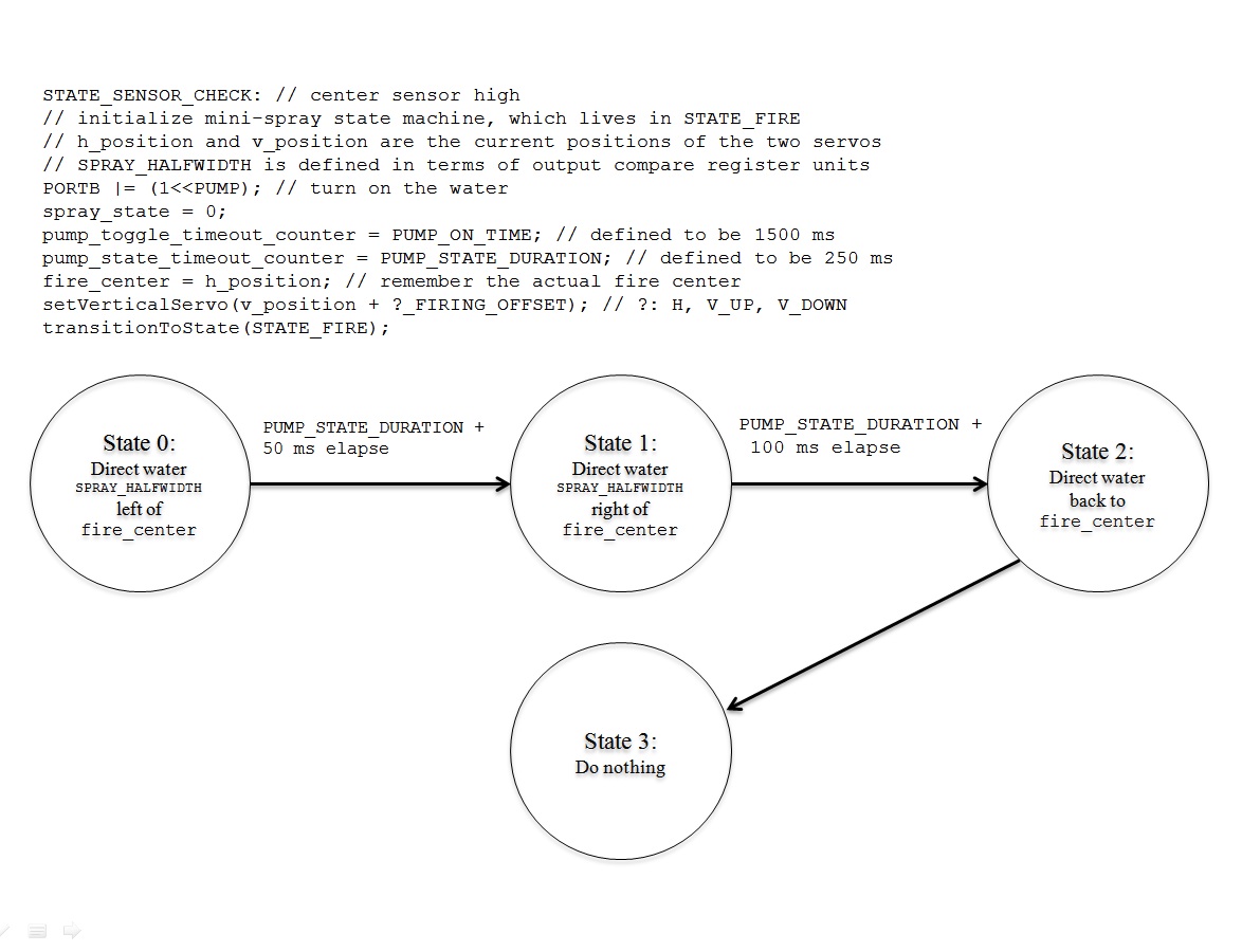
Figure 8: Shown above is a detailed look at the miniature state machine governing the spraying routine that our system initiates when it wants to extinguish a fire. This miniature state machine lives inside of STATE_FIRE and executes while STATE_FIRE is waiting on pump_toggle_timeout_counter to expire. Though the spray state machine enters a dead-end state, the system state machine will leave STATE_FIRE when pump_toggle_timeout_counter reaches 0. The next time it is necessary to spray water, part of the code (reproduced above) in STATE_SENSOR_CHECK will reset the spray state machine before the system enters STATE_FIRE.
Results top
Demo
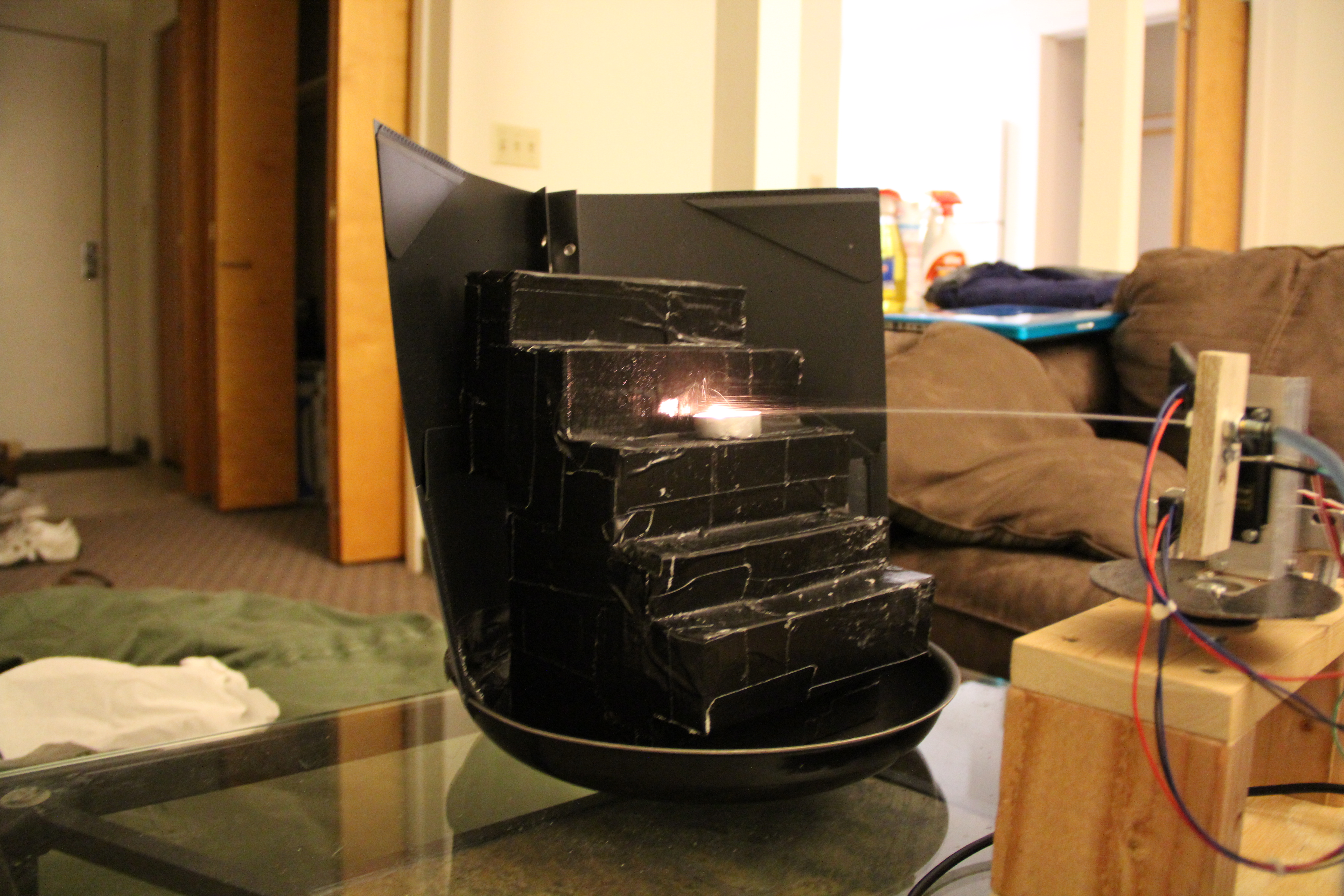
For testing and demoing our project, we designed a testing apparatus that consists of four different ledges of varying heights upon which we can place candles at a wide range of horizontal and vertical positions. Although our system did not always extinguish all of the fires presented to it very rapidly, it was able to successfully extinguish fires of varying horizontal locations at all four heights. For example, in the demo we gave to Professor Land, although our system was sluggish to detect all four fires presented to it (one on each ledge), we left it running while we explained to him how the system worked. By the time we had finished our explanation, our system had successfully detected and put out all four fires. Refer to Figure 9 below for a picture of our testing apparatus. Also included below is a YouTube video demonstrating a run where our system fairly quickly identifies and extinguishes three out of five fires presented to it at varying heights (it was edited in to replace the beginning of our aforementioned sluggish demo).
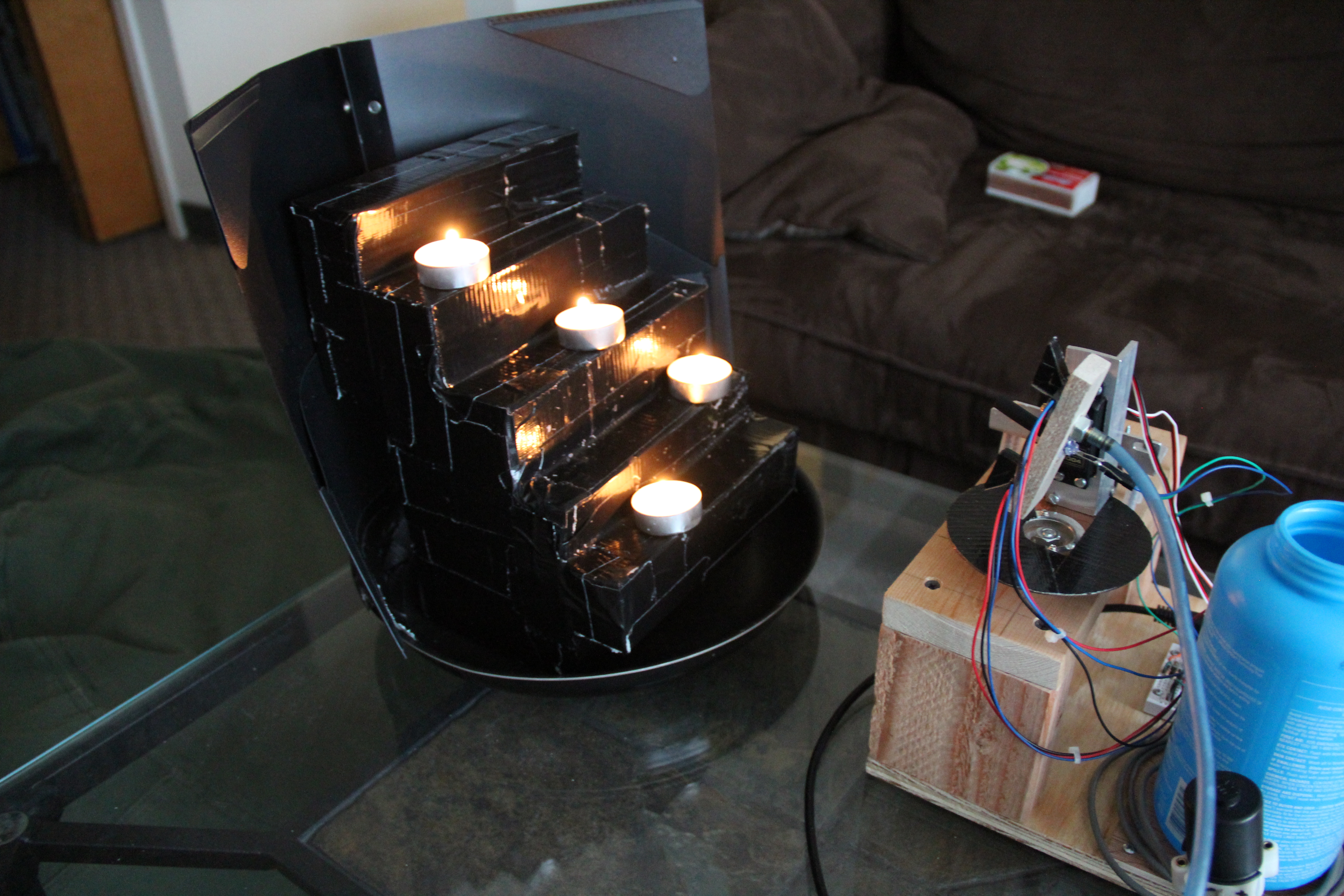
Figure 9: Pictured above is our testing apparatus demonstrating its ability to hold candles at various horizontal and vertical positions in front of our fire-extinguishing device, alongside the device itself. The testing apparatus is constructed out of cereal boxes, made waterproof, flame resistant, and stylish via duct tape. It allows us to test our device’s performance when challenged by targets at varying locations without worrying about making a mess.
Precision and Speed of Execution
As mentioned above under Servo Subsystem, our system has 400 possible horizontal positions between its leftmost and rightmost facings and 175 possible vertical positions between the upper and lower limits we set. Although we have only estimated the amount of degrees that these poles allow our system to sweep in each direction, they result in the following estimated precisions for our servos’ horizontal and vertical positions: (150°/400) = 0.375 degrees horizontally and (70°/175) = 0.4 degrees vertically. Allowing for some considerable error in our estimates for the degree sweeps, we can still say with reasonable confidence that our system is capable of precisely positioning its servos within ±0.5 degrees.
Our system takes approximately 3.2 seconds to perform a full horizontal sweep and 0.7 seconds to scan vertically to either its maximum upward position or its minimum downward position from its initial center position. Since candle fires hardly ever move, this execution time is completely reasonable. Changing the system’s scanning speed is just a matter of changing the constant (called SYNC_DELAY) that determines the delay between successive commands to update the servos’ positions. However, we found the system to operate most smoothly with this delay set to 8 ms, which results in the execution times already reported.
Accuracy
Accuracy is a bit harder to define, as there are several different aspects of our system’s performance to consider. For example, our fire detection accuracy was imperfect. Although we encountered no false positive detections in our tests, there were several instances where the sensor interrupts failed to trigger during our device’s horizontal sweep routine. If we look at our detection accuracy on a per run basis rather than a per sweep basis, however, our detection accuracy is much higher, as in our tests our sensors always triggered eventually. We believe this lack of consistency is due to variations in the fires’ intensities. We noticed that as our candles burned longer, they tended to get brighter and consequently were more easily detected. Obviously, our system’s upper and lower sensors sometimes trigger in the presence of non-fires, since they are sensitive to visible light. We don’t consider this behavior detrimental to our system’s detection accuracy, however, since we account for these shortcomings in our approach by using the central sensor to verify all potential threats before spraying them with water (ie, a target is not officially “detected” unless it is detected by the central sensor). An astute reader might notice that our central sensor still does not guarantee that the target it senses is actually a fire. Although background IR is rare, it is feasible that some household electronic device that is not on fire could produce a signal in the 940 nm range. One way to make the central sensor’s fire discrimination more robust would be to combine it with another sensor sensitive to a different kind of information. Some of our plans for such a setup can be found in the section below called Alternative Designs & Future Work. Nevertheless, our device made no false positive identifications and initiated no unwarranted sprayings during testing.
In addition to detection accuracy, our system’s spraying accuracy and success rate in extinguishing candle fires are also relevant performance measures. As noted above, we control our system’s water-spraying routine with a special state machine that sweeps the water jet back and forth slightly (governed by SPRAY_HALFWIDTH) around the detected location of a fire. Doing so increases our system’s extinguishing success rate and is necessary since flames often sway slightly. Although we do not have exact quantitative data for our system’s spraying accuracy, it was qualitatively pretty good, provided we had set the proper offsets for each sensor and scanning direction. That said, tuning all of the offsets perfectly was quite difficult since they are not completely independent of each other. Our system’s horizontal spraying accuracy was generally better than its vertical spraying accuracy, although this fact might just be an artifact of our prioritization of achieving good horizontal performance. Occasionally, our system sprayed water but missed the target source. Usually, it was so close that the water touched the flame, and eventually when it scanned back to the fire another time, it would actually put it out. Like its spraying accuracy, our system’s horizontal extinguishing success rate (success rate at the default height) was better than its vertical extinguishing success rate (success rate at varying heights). On a per run basis (allowing multiple passes before turning off the device) before we added vertical functionality, our system’s horizontal extinguishing success rate was near 100%. After adding vertical functionality (which required further restricting our central sensor’s field of view and retuning some of our offsets), our system began to require more passes before successfully identifying and extinguishing horizontal fires, but its per run horizontal success rate was largely unaffected. Our system’s vertical success rate was less stellar. Although the system hit all of its targets in the only test where we left the system running for a long time (the demo we gave to Professor Land mentioned above), its vertical success rate for shorter runs was noticeably imperfect. Usually, it performed well on targets at or near the default height, but it missed some targets farther away. The video above is one of our system’s better runs (loosely defined as achieving a good per run extinguishing success rate in a short amount of system uptime). It demonstrates a case where our system’s overall extinguishing success rate with vertical targets was 60% (three out of five fires).
Usability
Our system was designed to detect and put out fires autonomously. Therefore, it requires little-to-no human interaction, besides when it is initially turned on and when the water reservoir needs to be refilled. The current iteration of the system is still very much a proof-of-concept or prototype. It is not yet practical enough for our hypothetical use case as an upgrade to a typical residential fire protection system. As is, it can detect and extinguish small fires at a short, fixed distance. In order to be practical, it would need to be capable of extinguishing both larger fires and fires at varying distances from the front edge of the device. Although our pump is capable of propelling water much farther than the 1 foot distance (its estimated range is 8 feet) we used during development and testing, our sensor’s detection ranges max out (and get flakier) around two feet, so they would need improvement. Refer to the Alternative Designs & Future Work section below for some potential means of addressing this issue.
Conclusions top
Results vs. Expectations
Given that we designed our project from scratch, the design process was one of our project’s most difficult aspects. Initially, we just had the vague idea that we wanted to make a device capable of targeting fires and putting them out at a distance. We went through numerous conceptual designs, refinements, and simplifications before finally arriving at a version of the project feasible for the course: a tabletop candle extinguisher. Although our project ended up being smaller in scale than a practical automated residential fire suppression system, it allowed us to explore most of the relevant concepts and challenges in the same problem space.
While we developing our design, we were most concerned about three things: whether our system would be able to detect targets at least a foot away (anything closer did not seem challenging enough to us), whether our system would be able to suppress fires at least a foot away (to match the detection range), and whether our system would be able to handle targets in two dimensions. We were able to meet our detection goal using by passing our system’s weakest sensor, the central sensor, through an amplifier before thresholding it into a digital signal. Although in an earlier design we considered using air to extinguish candles instead of water to avoid making a mess, we ultimately decided to use water because doing so allowed us to meet our suppression goal more easily (using a simple pump vs. designing a vortex ring generator). Since we were most uncertain about meeting our final goal — identifying and suppressing fires at varying vertical positions, as well as varying horizontal positions — we set an intermediate goal for ourselves to be able to put out horizontal fires. However, keeping in mind that we wanted to aim for vertical support as well, we designed our hardware for the system to have support for both horizontal and vertical positioning. The plan was that, if we couldn’t get vertical support working, we could always keep our system’s vertical servo at its center position and include only horizontal support in our software. In the end, we were pleased with our system’s horizontal performance, but we were a bit disappointed in our system’s vertical performance. That said, the course staff told us our project would be difficult, so we are still proud that we were able to achieve a moderate degree of success in both target dimensions.
Alternative Designs & Future Work
Naively, one might assume that a camera-centric approach is the best way to implement an automated fire extinguishing system capable of aiming at targets at arbitrary points in space. Indeed it is conceptually familiar, and it would likely be very effective. However, using a camera was impractical for us for several reasons. Although USB webcams can be obtained quite cheaply, cameras with a more compatible interface for a microcontroller like the ATmega1284p are significantly more expensive4. Thermal imaging cameras, which seem most ideally suited to our task, are even more expensive. A recent indiegogo project, the Mu Thermal Camera5, was able to cut the cost down to around $325 for a smartphone-based thermal camera, but even their product would lie outside of our budget. Aside from cost concerns, there are also issues with (i) having enough memory to store images waiting to be processed and (ii) having enough computational power available to process images in a reasonable amount of time. The first issue could potentially be solved by processing an image as an incoming stream of data and remembering only points of interest, as long as the timing constraints on processing time are loose. The severity of the second issue depends on the specific algorithm used to analyze an image, but we expect it would be significant in any case. Finally, even if we were able to identify points in space as fires using an image produced by visible light (based on targets say, eg., being orange), we would still need some way to guard against false positives (eg., not all orange objects are fires). Given these concerns, we opted to use the three-phototransistor system described above instead.
As mentioned above, our system’s central sensor is not perfectly fire-specific and has the potential to identify electronics emitting short IR signals at 940 nm (like the LTE-4208 we used in Lab 4) as fires. Pairing the current center sensor with a sensor capable of responding to an orthogonal source of information could improve our system’s resistance to false positive detections. For example, there are non-contact IR thermometers available that respond to long IR in the 5-14 micron range. We were initially planning to incorporate one such sensor, the MLX90614, into our design. Since it is capable of measuring an object’s temperature between –70°C and +380°C (presumably maxing out when aimed at a candle flame, which we expect to be burning close to 1000°C6), we could use such a thermometer to improve our system’s decision-making process. In a hypothetical future design, in order for a target to be a threat in need of extinguishing, we could say that it needs to be both hot (eliminating false detections from electronics devices transmitting in the short IR spectrum) and emitting IR radiation in the 940 nm range (hopefully eliminating false detection on heaters, humans, etc.). The MLX90614 was pretty expensive and would have greatly increased the tangle of wires that our servo system had to move though. We eliminated it from our prototype design since we noticed no performance deficits without it for our demoing purposes.
There are also a few improvements we could make to the general method we use for detecting threats with all of our system’s sensors. Rather than setting an absolute threshold for each sensor, we could instead analyze how their signals change during a scan. Doing so, our system could detect any abnormal peaks in the sensor signals and later investigate the areas corresponding to those peaks more closely. Setting an absolute threshold was especially tricky for our system’s up/down sensors because of the different levels of ambient light in every room (recall that they are sensitive to visible light). Currently, our system performs best in dimly-lit rooms (which actually matches our hypothetical residential setting when users aren’t home and the lights are off).
In addition to the above improvements, it would be nice to increase our system’s effective range. Although amplification allowed our system to have acceptable performance at a distance of 1 ft., the detection rate for weak candle fires occasionally suffered. Of course, larger fires are easier to detect, but we would need to improve our system’s detection range considerably (probably by a factor of at least ten) if we wanted it to be practically or commercially viable. Such a range increase is plausible using a lens system instead of or in addition to amplification circuits like those shown above. There exist lenses capable of focusing and passing even long IR7 (8-14 microns in wavelength). Like the IR thermometer, however, the increased cost and design complications caused us to eliminate this component from our prototype design.
Finally, it would be nice to reduce the cost and footprint of our device (maybe it could look like a smoke detector and hide any extra hardware in the ceiling), as well as add additional peace-of-mind via features like automatic calls to the owner’s cell phone or the fire department depending on the severity of detected threats.
Safety, Ethical Considerations, & Standards
Obviously, we needed access to live fires to test and demo our device. We used candles to ensure that our fires were detectable, manageable, and safe. Whenever we had any candles burning, at least one of us was close by monitoring them to minimize the risk of spreading the fire from the candles to the rest of the room. Ideally, if we were to accidentally start a fire after getting our device operational, it would spring into action and extinguish it anyway! Note, however, the disclaimer at the top of this page.
In a previous design, the voltage regulator powering the servos was getting painfully hot due to delivering current near its maximum rating almost all the time. We solved this issue by reducing the speed at which our system’s servos scan, which also gave our system increased stopping precision.
Although there aren’t many overt ethical considerations in our project, we believe we have followed the IEEE Code of Ethics. Our device does not do anything crazy like gather customer data and spread it over the Internet, nor would it ever target people (and even if it did, the water pressure level is harmless). We made sure to behave in a responsible and safe manner when constructing and operating the device, and in this document we have disclosed all information about our device pertinent to the public. As far as we know, there are no relevant standards or regulations affecting our device as it stands now (it’s just a prototype). There are, however, certainly some standards that we’d need to research further and meet before deploying an improved version of our system in homes as a commercial product/actual safety device. Although it measures incoming IR, our system transmits no significant signals, so regulations from organizations like the FCC are not a concern.
Intellectual Property
We designed all of the hardware and software components of this project from scratch (other than the UART code). Upon writing this report, however, we discovered that this project is probably unpatentable due to an existing patent on a very similar idea/device8.
Appendix top
Budget
| Item | Unit Cost | Quantity | Total Cost | Source |
| white board | $6 | 1 | $6.00 | Phillips 238 Lab |
| solder board | $1 | 1 | $1.00 | Phillips 238 Lab |
| MCU board | $4 | 1 | $4.00 | Phillips 238 Lab |
| Max233CPP | $7 | 1 | $7.00 | Phillips 238 Lab |
| RS232 connector | $1 | 1 | $1.00 | Phillips 238 Lab |
| ATmega1284p | $5 | 1 | $5.00 | Phillips 238 Lab |
| sip or header socket/plug | $0.05 | 14 | $0.70 | Phillips 238 Lab |
| LM358 op-amp IC | $0.55 | 3 | $1.65 | Phillips 238 Lab |
| BUZ73 MOSFET transistor | $1.60 | 1 | $1.60 | Phillips 238 Lab |
| Futaba S3004 Servo | $12.99 | 2 | $25.98 | Amazon |
| 2-man 2.1mm splitter | $4.28 | 1 | $4.28 | Amazon |
| 12 V, 5 A PSU | $11.50 | 1 | $11.50 | Amazon |
| 12 V, 1 A PSU | $5.69 | 1 | $5.69 | Amazon |
| LM7805CT-ND 5V regulator | $0.67 | 1 | $0.67 | Digikey |
| TSL12-S-LF-ND | $1.48 | 2 | $2.96 | Digikey |
| LTR-3208E | $0.46 | 1 | $0.46 | Digikey |
| windshield wiper pump | $0 | 1 | $0.00 | scrap/salvage |
| wood, metal, screws | $0 | 1 | $0.00 | scrap/salvage |
| Total Price | $79.49 |
Datasheets
References
- 1Servo City. How do Servos Work?
- 2Bruce Land. Prototype Board for Atmel Mega644
- 3Bruce Land. ECE 4760: Laboratory 4 – Tachometer and motor controller
- 4LinkSprite. LinkSprite JPEG Color Camera Serial UART Interface (TTL level)
- 5John and Charles McGrath. Mu Thermal Camera
- 6Wikipedia. Candle
- 7Edmund Optics. Infrared (IR) Fresnel Lenses
- 8Benjamin Tan. Apparatus and method for sensing of fire and directed fire suppression
Vendor Sites
Code
Distribution of Labor
For the most part, we worked on the project simultaneously and evenly. Trevor did a bit more work on the component selection and hardware design, and Dawn did a bit more work on refinements/tuning for things like the sensor thresholds and offsets.
Acknowledgements
We would like to thank Professor Bruce Land for his help in breaking down our initial idea to make it a more feasible project for this semester. Additionally, we would like to thank all of the teaching assistants who spent countless hours in the lab with us, providing us the time and guidance we needed to successfully complete our project.
We'd also like to thank Omeo Quddus, Roland Krieger, and Cameron Glass, who gave us permission to copy their style and layout for this report.