This project is intended to perform the role of a goal-keeper in the popular arcade game Air Hockey.
In this project, the robot shown below senses a puck coming toward it and moves in the direction of the puck's motion so as to stop it. This problem was identified as fairly challenging to solve based on two metrics. Firstly, Air Hockey is fast paced and designing a highly responsive control system seemed exciting. Secondly, most prior solutions to this problem have been attempted with robot arms that are vastly greater in cost than the solution presented in this project.

The following is a video demonstrating a prototpye goalie.
© 2013, Vinay Farias
The robot is designed to be an autonomous entity, in that it is battery powered and does not require human input to locate a moving puck in a game of Air Hockey. So as to behave optimally, the robot is most likely to lurk around the region near the goal rather than move end to end while tracking the puck. This is due to an optimization in sensing distance that we felt necessary to introduce in the sensing mechanism of the robot as discussed in the Hardware section. Overall, the robot performed well in the absence of a lot of noise from other sensors in the environment. Even so, owing to the nature of the sensing, i.e. sensing planar sound waves with ultrasonic sensors, there was notable loss of sensitivity in sensing. This was improved by altering the geometry of the puck as shown in the Pictures section.
Shown below is an illustration of the system as a whole. The ATMEGA 1284 MCU takes in echo patterns from each of the sensors, interprets them and accordingly actuates the robots motors.

© 2013, Vinay Farias
The hardware employed in the project spans some fairly basic elements, each of which will be described in detail. A listing of the components includes:
- 1 Atmel 1284 Microcontroller.
- 1 LM293D Quadruple Half-H Drive
- 3 Ultrasonic Sensors.
- 1 pre-cut circular chassis.
- 2 30:1 Micrometal Gearmotors with mounting brackets.
- 1 pair of wheels.
- 2 9V batteries.
- 2 SPDT switches.
- 1 LAZ 9V-5V voltage regulator.
- 1 PCB-like Plastic Breadboard.
- 3 metal spacer mounts to mount the breadboard.
- 2 3/8" metal ball bearings.
The system can be broken into two main subsytems - sensing and actuation. The sensing subsystem takes in inputs from its surrounding and interrupts the microcontroller when it senses a moving puck. The 1284P microcontroller (MCU) then uses this interrupt to signal the acutation subsystem to move the robot in the appropriate direction as required.
Sensing Subsystem

Figure 1: Sensing Subsystem
The system above represents the bulk of the interaction between the MCU and Sensors in our system. The sensors were placed in a V-Shape as in Figure 2 so as to capture and track any possible change in the movement of the puck; the exact functioning of this is described in the next paragraph.

Figure 2: V-Shape
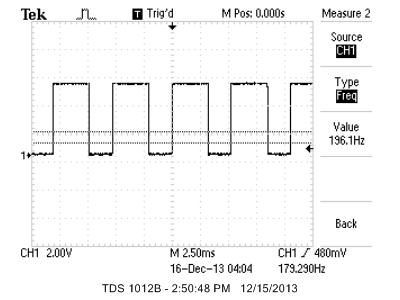
The left ultrasonic sensor works to actuate the robot to the left depending on whether the puck is in its echo path or not. This can quantifiably be noticed in the echo pattern (See Results Section) delivered by the ultrasonic to the MCU as every pulse-width in the echo narrows as the ultrasonic notices the puck in its path and widens as it notices the absence of anything in its path. Experimental results helped to generate a threshold of a 3ms echo pulse meaning the absence of a puck. These observations were made by scoping the echo pattern of each sensor while plugged into a white-board. As shown in the Results section, each scope image represents an echo pattern for a distance of 5cm, 10 cm, 20 cm, 30 cm and more than 30 cm away from the sensor respectively. The last scope image, therefore, effectively represents nothing detected by the sensor; hence the noticeably large pulse-width and our conclusion to use 3ms as a threshold for detecting or not detecting a puck. The same logic applies to the right and center sensors, the scope images of which are almost identical to those in shown in the Results section. Although the center ultrasonic operates the same way as the left and right sensors, its functionality in the robot is analogous to that of a brake in a car. The exact place of this is described below and shows the logic behind the V-Shaped sensor setup of Figure 2.
The V-Shape was deemed optimal as it fit and amply satisfied several scenarios below:
- Consider the event that the puck moved from somewhere in between the center and right sensors toward the left. When the puck intersects the trigger pattern of the left ultrasonic, this would actuate the motors on the robot, via the left ultrasonic's echo, to make it move toward the left and continue to move toward the left until the puck intersected the trigger pattern of the center sensor; which is when the brake would be applied, causing the robot to stop in its tracks. The same applies for when the puck moves from somewhere in between the center and left sensors toward the right.
-
In the event that the puck is sent straight down the board, the robot would trivially detect, stop it and not move at all.
-
Finally, considering that the puck was banked perfectly on one of the edges of the air hockey table, we figured that the puck would need to hit the edge a minimum of 2 feet away from the robot to make a decent attempt on goal. We therefore narrowed the range of the ultrasonic sensor to around 1 foot so as to fully encompass a region of interest for the robot without the opportunity of letting it get confused or lose information off of the edges of the air hockey table. This implies the robot should move only within the area on the Air Hockey table that is near the goal it is attempting to defend.
To sum up this section, it would seem useful to talk about why the HCSR-04 (See Figure 3) and more importantly, why ultrasonic sensors, were chosen as a sensing mechanism for this project. The HCSR-04 was picked through a process of elimination and after carefully going through every alternate sensing mechanism available to us. This included Infra-red, lasers as well as better ultrasonic sensors. Initially it was posited that the use of lasers would provide the most accurate sensing data for a moving object, i.e. the puck, to feed data (in the form of a stable interrupt) to our MCU. However, there were several issues with this. To begin with, we were constrained by a tight budget and employing a set of three laser emitter and receiver pairs was deemed too expensive given that we required quick and responsive DC motors to actuate the robot in the direction of the puck; these motors represented a fixed and relatively high expense in themselves. We then moved on to infra-red, but given our inability to deploy this effectively in lab, we decided to scrap this idea. Finally, after looking at several ultrasonic sensors and their datasheets online, we decided to settle on the HCSR-04 as it had the range we needed to operate within and was fairly inexpensive as well. Even so, apart from this, the HCSR-04 represents a very flexible mode to sensing, allowing the opportunity for a designer to easily vary the range of the sensor based on how long and how often the trigger signal is applied to it. This represents some clear benefits given that this sensor can thereby be mounted on chassis of varying heights as it has a fairly wide angle of 15 degrees to receive the echoes of the signals it sends out.

Figure 3: HCSR-04 Sensor; See Trigger, Echo and VCC/ GND pins
Actuating Subsystem
As shown below in Figure 5, the Actuation Subsytem is comprised of the MCU sending just 2 logic outputs to an H-Bridge (See Figure 8) that in turn controls 2 DC metal gearmotors (See Figure 7) that are similar to the 12mm motors manufactured by Sanyo. Two attempts were made in creating the actuation subsystem. Initially, an attempt to extend Lab 4 was made as this seemed like a logical way to extend current understanding regarding motor control. In addition to this, the PID control encouraged the idea of allowing a graded motor actuation depending on the distance of the puck from the robot using the PWM output on B3. However, a serious flaw of this approach was uncovered when we moved from trying to just actuate the motor via the sensor in one direction toward actuating it in both directions. A little research online resulted in the realization that using a dual h-bridge to accomplish this two-way actuation was the way to go.

Figure 4: Acutation Subsystem
The H-bridge works in tandem with 2 control signals generated by the MCU over the ports B0 and B1 (See Table 1). Notice two things. Firstly that the motors and Motor Power are directly connected to H-brdige and secondly, the model of the H-bridge used, i.e. LM293DNE. Both these observations are closely coupled in that since the motors are attached to the H-Bridge, there is likely to be reverse current that might end up burning out one or more transistors on the H-Bridge. This is why the LM239DNE was chosen; the D indicates the presence of diodes at each of the motor ports of the H-Bridge so as to allow current flow only in a single direction over each channel.
Each of the Control signals actuate the motors according to the values in Table 1. However, the control signals themselves are determined via measurements taken by each of the sensors as discussed above. These measurements are simply pulse-widths and result in actuation depending on whether or not the pulse-width is within the range the initial experiments we conducted deemed reasonable. Accordingly, pins B.0 and B.1 were set HIGH or LOW.

Table 1: H-Bridge Control Signals
Specific to picking the motors, a little math yields how the type and specification of the motor was deemed appropriate. Equation 1 is instructional in providing an idea as to how gear-ratios affected the choice of motors used. The Sanyo metal gear motors in the project were chosen as they are both reputed and simple DC motors that were fitted the requirements of the project. Each type of motor was rated by RPM at a stall current of 6 V, and varied by gear ratio. The ratio used in the project, ie. 30:1 was the lowest available so as to meet the budget requirements. As seen below, the lower the gear ratio, the higher the speed of the motor, hence the choice of the KM-12FN20 motor.
}{(Gear Ratio * 60)})
To maximize, the speed generated by our setup, we used the motors datasheet to generate the maximum RPM of the motors at several voltages ranging from 3V, the minimum required to turn the motor, up to 9V, the maximum for this purpose. Figure 1 shows a graphical progression of RPM vs. voltage whereas Figure 2 extends this observation by Formula 1 to represent the maximum speed the motors can generate for the chassis.

Figure 5: Speed vs. Motor Voltage Figure 6: Speed vs. RPM @ Motor Voltage


Figure 7: Metal Gear-Motors Figure 8: Dual H-Bridge with Diodes LM293DNE
Miscellaneous Issues and Fixes in Hardware
Power management was a significant issue experienced through the course of the project. This was fixed by connecting both logic power to the MCU as well as motor power to the H-Bridge via SPDT switches. This had a two-fold benefit. Firstly, it helped isolate any issues related to bad soldering resulting in leakage currents. Secondly, it enhanced the robots ease of use with respect to scoping voltages, reprogramming the MCU as well as changing batteries simply because several connecting wires and headers would then not have to be unsoldered or disconnected.
Figure 6 depicts a picture of the robot and all its hardware in its final state.
Final Circuit Schematic

Figure 9: Final Circuit Schematic
© 2013, Vinay Farias
The most challenging problem in writing the code for this project is achieving co-ordination between the three sensors so that each of them have enough time trigger and interrupt the MCU. As such, the issue then is scheduling each of them in such a way so as to achieve minimum reaction time. The HCSR-04 sensor measurement protocol requires that before any echo signal is received, the Trigger must be held HIGH for more than 10uS. This trigger would cause the sensor to send out an 8 cycle burst of 40kHz signals, thus leading to an echo. The echo contains a pulse whose width is proportional to the distance at which an object has reflected the sensor's trigger burst. The width of the pulse has a range of 150us-25ms in theory. The datasheet further suggests that the triggers should only be sent once every 60ms to achieve the maximum distance detectable by the sensor. For our purposes, we succeeded in reducing this latency to 6ms, so as to achieve a maximum range of 1.1 foot (34 cm). This was chosen as a suitable period as each of the three sensors is triggered safely every 2ms within this 6ms window. This ensures that even though the ultrasonics are angled away from one another, there is sufficient time to fully trigger each with a timer.
Following successful triggering, the next task is then to measure the echo's pulse width. The logic here being that if the width of the pulse is smaller than a specific threshold, the motor will be actuated in the appropriate direction. We tried two approaches to solving this problem.
Initially, to measure the pulse width, we first tried to sample the echo signal by taking 4 signal readings every milli-second. These readings were then saved into an 8-bit shift register. A motor task was then run to read this register and determine if the pulse was narrow enough to trigger the motor. However, after experimenting with this method, we realized that too much information is lost due to a sampling rate of only 4, meaning that every reading obtained had a chance of being inaccurate due to slow sampling. The sampling rate could be increased, but at then it would take too long to enter and exit the ultrasonic ISRs resulting in many such ISRs choking and therefore missing. The section on Conclusions sheds more light on this implementation decision.
The second and final approach was more conservative. It involved setting up the triggers of the echo to be used by the three external interrupts we have on board; INT0, INT1, INT2 on pins D.2, D.3 and B.2. Timer1 is set to run at 1024 pre-scalar so every tick is 64us. On initialization, each of the external interrupts are triggered by a rising edge of an incoming echo signal. Inside the ISR, the current count of timer1 is recorded and the external interrupt is set to be triggered next on a falling edge. The next time the interrupt is triggered, the ISR checks whether the interrupt was triggerred on a falling edge and determines the pulse width by subtracting the current Timer1 count with the previously saved value. The edge on which this ISR is flipped again to trigger on the rising edge and this process repeats continuously. This process results in a very accurate pulse width reading and the ISRs are still short enough to run correctly altogether.
A few implementations were attempted while trying to schedule tasks. Firstly, since there are many things running concurrently in the system, we thought that it would be a good idea to use the TinyRealTime (TRT) library to handle these threads. We also triggered the three sensors at the same time in one task and read all three echoes in another task. There was an additional task to handle motor actuation. However, it was observed that TRT does not offer enough precision in task controlling resulting in the system being too unstable to be used. Following this, as described above, a switch to using interrupt service routines was made although triggering all sensors at the same time was retained. This also did not work although we had complete control of the board and through the UART interface observed that an echo meant for one sensor was also being read by another sensor. Hence, in the final design, each sensor is triggered 2ms apart so that each sensor will only be triggered once every 6ms, which was found to be a good value for both control and precision.
The final tricky thing was to find the furthest the sensors could be able to detect a puck. When holding the sensor in the air, it successfully detects a puck or any object for that matter upto 1m away. However, when kept close to the ground as seen in our design,some of the Trigger signals will bounce off the ground and reflect back as false echoes, thus causing false positives thereby actuating the robot incorrectly. In the final design, with all the sensors mounted on the robot, a threshold of about 34cm or 1 foot was observed to do the best job of detecting the puck and resulting in proper functioning of the robot.
© 2013, Vinay Farias
Overall, the design goals were successfully achieved. The sensors are triggered correctly and the echo signals change appropriately as a test object moves toward and away from the robot. The motor and H-bridge also work accurately based on the control signals given to the H-Bridge by the MCU. In sum, when a puck approaches the goal, the robot reacts quickly moves toward it and attempts to block it.
However, we found the responsiveness of the robot to be a bit slow. Further testing the design and experimenting with different thresholds/sampling/sensor positions, we found that since the puck is round in shape and more over short in height, alot of the incoming planar sound waves do not return back to the echo and are dispersed elsewhere; this causes the echo signal to be too low in energy to cause a logic high. Hence, there are occasions where the puck just zooms past or gets too close to the robot before the motor is actuated. We attempted to fix this issue by attaching a solid object in the shape of an X to the puck (See Pictures) so that the ultrasonic signals are more easily reflected. Moreover, we found that ambient noise in the room can sometimes cause the sensors to randomly trigger the motor.
Safety on this project is mostly concerned with the shorts that resulted from soldering small parts in tight spaces so as to achieve a compact design. Initially, we had a short in the circuit so the board drew too much current and drained a 9V battery in as little as 25 minutes. The circuit was immediately powered off and tested rigorously to find the short and ensure both safety for users and general functionality of the system. As it were, the short resulted from the usage of metal spacers used to mount the plastic breadboard on the chassis. Each end of one spacer was connecting the VCC and GND rails.
Below are a set of Oscilloscope images showing the accurate functioning of the ultrasoncic sensors. They each show an echo pattern and proved vital in designing software to run the motors.
-
Ultrasonic Echo at 5 cm

-
Ultrasonic Echo at 10 cm

-
Ultrasonic Echo at 20 cm

-
Ultrasonic Echo at 30 cm

-
Ultrasonic Echo at further than 30 cm
© 2013, Vinay Farias
The design process for this robot was carefully iterated through as in the section on Hardware and how each of the components were picked. It can be stated, with some level of confidence that given budgetary constraints, we have presented the most precise solution to the problem we set out to solve. Without these constraints, we could have achieved pin-point accuracy should we have been able to afford Class D lasers.
Since the HCSR04 ultrasonic sensor is used primarily for educational purposes it was verified to be safe for use in our project without being able to cause any harm bodily or otherwise to us or any other persons. We believe there is a strong case for publishing our solution once we have a chance to improve it with slightly looser financial constraints. Such an inexpensive idea, to the best of our knowledge, of 1 person Air Hockey does not currently exist and this is where we see a strong opportunity for ourselves.
Potential Extensions
As seen in the Software section, the shift register approach has some definite positives simply because it lends the goalie the notion of memory regarding its opponent. In the initial implementation the shift register was used to store dynamic information about the presence or absence of the puck. However, given time, in a more sophisticated extension of this project, it would be nicer to implement a goalie that could be set to varying levels of difficulty simply by storing how many times it successfully blocked the puck. Depending on how many past successful stops were made, the goalie could then decide to move several times slower so as to greatly increase the probability of the next attempt on goal to be a success. The frequency in the occurrence of this would therefore reduce as the levels of difficulty increased.
Conformity with Standards
The code for this project complies with the C Language Standards set by ANSI. In addition, the HCSR-04 ultrasonic sensor modules, emit signals at a frequency of 40kHz, which is outside of the human hearing range and thereby complies with the IS 2264 set of Preferred Frequencies. The HR-SC04 modules also conform to IEEE 1451 - Standard for Sensors and Actuators.
Futhermore, USB 2.0 Stadards A & B were both availed of so as to aid in debug software related to the sensors. Simply put, the usage is of the UART to debug makes mentioning this standard important.
Ethical Considerations
During the course of the project, our team tried our best to comply with the IEEE code of Ethics. When working in the lab, we followed all the rules laid out by Bruce to ensure safety for both the team and everyone else in the lab. Examples include wearing protective glasses when using the soldering stations or drilling machines. As for the product, a lot of thoughts was put into making sure it is safe for the users. There were no high current or voltage devices used that might have been dangerous. Our circuit was also checked many times to ensure no shorts or inclusion of dangerous materials that might have resulted in overheating or possibly fires. Prof. Bruce Land and each of the TA's proved extremely helpful in getting our final design to work. We also offered advice to other groups on ultrasonic sensors as we had tried and tested a very reliable variant. Lastly, all the data we collected accurately reflects the performance of our design. The limitations of our design have also been reported so as to serve as guidance.
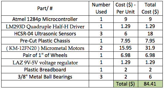
Cost Analysis
References
- 2013, Metal Gear-Motors, wwww.solarbotics.com
- 2013, HCSR-04 ultrasonic sensor datasheet, wwww.elecfreaks.com
- 2013, L293, L293D QUADRUPLE HALF-H DRIVERS datasheet, wwww.ti.com
- 2013, KM-12FN20 DC Motor datasheet, Shezhen Kinmore Motor Co. Ltd.,wwww.sparkfun.com
© 2013, Vinay Farias
Available on Request. E-Mail
Vinay Farias
© 2013, Vinay Farias