"A system designed for lecturers who use both projectors and blackboards."
Introduction top
The most fitting way to explain our final project is to describe it as a smartboard replacer. Through the use of an IR camera, we read the position and movement of an IR LED to interact with a remote laptop. The systems comes with two modes, whiteboard mode and blackboard mode, which can be selected by switches. In whiteboard mode, the user can interact with a projected image to do simple things like scroll through a page or move a mouse. In blackboard mode, the user will be able to write on a blackboard and have the IR camera trace the movements and draw it on paint and save the images. The goal was to create an affordable smartboard replacement for classrooms.
High Level Design top
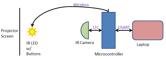
Our system is set up in the following manner: there is a user with an IR source and a few buttons that feeds as an input to the microcontroller. The IR source movement and position is read by an IR camera while there is a wireless protocol to communicate the buttons with the microcontroller. The microcontroller will process the input data into the correct format such as position and actions to take. Then the microcontroller will send that data to the PC using serial communications. The PC will use Matlab which will control actions on the PC such as mouse movements or drawing on paint.
Rationale and Source
The idea for our final project came from a moment in lecture when Bruce Land tried to scroll on a projected image on the whiteboard. "Wouldn't it be great if you didn't have to walk back to your laptop but could scroll literally on the projected image?". Then a lecturer would not have to go back and forth between the board and the laptop which is running the presentation.
Logical Structure
There are three major subsystems that make up this project. The first is the user interface which consists of a 2 switches, 1 button, a few IR LEDs, and a wireless transmitter. The buttons and switches control the actions that the user wants to perform. This information is sent to the second subsystem, the microcontroller. The microcontroller takes in the input from the user interface and inputs from the IR camera that senses the user with the IR LEDs. The microcontroller does some processing and then sends the information to PC and Matlab, our third subsystem, using a USB serial interface. Matlab takes in the information and actually does the actions we want on the PC and by extension onto the projector.
system overview
Hardware/Software Tradeoffs
The majority of our projects runs off software. This is because the software is what calculates the inputs from the user and IR camera and figures out the actions that we need to take. This calculation of the inputs to required data to Matlab is not something that we would try to do in hardware since the data easy for the microcontroller to convert through software. However, a big challenge for this project was to get the hardware working. Although it looks simple, it is very difficult to get the IR camera to function due to its very specific needs. Furthermore, since there is no datasheet available, we have to rely on forum informaton and manual debugging. And finally, since it is not possible to buy the IR camera separately, we always have to scavenge an IR camera from a Wiimote. It's almost impossible to check if the IR camera has a problem or whether it's the code that has a problem.
Standards
In our project we use I2C to communicate from the IR camera to the microcontroller and USART from the microcontroller to Matlab. The wireless module works at 433MHz which many low power devices use.
Copyrights and Patents
Much of our information on the IR camera comes from sources on the internet, the originator being Kako. We also use some information from wiibrew.org. To do some of the Matlab to microcontroller communication, we refer to Hand-Motion Chess from SP2013, and by extension of Bruce's bird song code.
Software top
C Code
The majority of the work done on this project is through software. The software takes in the data from the IR camera and outputs it to Matlab to control the mouse movement and scrolling. To begin, we started with the most difficult part of this project: get a working I2C communication between the IR camera and the microcontroller.
I2C is made up of 4 wires: Vcc, Gnd, SCK(clock) which runs around 100-400kHz, and SDA(data) the line which data transmits on. The camera also required another input of 24MHz to run the actual camera. To simplify our lives and not write our own protocol, we instead started with Peter Fleury's I2C code for ATMEGA. The code uses the built in TWI (two wire interface), the hardware ATMEL version of I2C. It defines important function such as start, write data, and read data by setting the TWI register values.
However, this did not seem to work well for us and it seemed to write incorrect values and did not read the values from the camera correctly. It could have been a timing issue, but we could not make it work as some others groups did. One conjecture as to why it did not work is that the the I2C timing was incorrect. As the example code was meant for a specific chip, we might have required a different I2C clock rate. We did changing the frequency and some of the parameters in the I2Cmaster file, but they did not work. We did see data of some sort being transmitted, but it was garbage. A second reason that this could have been wrong is that the I2C protocol on the camera needed some specific way of handling writes and reads. The I2Cmaster file we actually used was designed to look at the specific registers in the camera and confirm we were writing. A third reason, and the one we believe to be the problem is I2C rep start. The use was to switch from a write to a read correctly since to read an output we must first declare where we are reading from by writing the address. The difference in the second I2Cmaster file is that it did not have a rep_start function but just called start again. This might encapsulate the previous 2 reasons and is why is the favored explanation for why Peter Fleury's I2Cmaster failed.
Instead, we used an I2C file from Kako. It also runs the I2C protocol, but is tailored to communicating with the IR camera, specifically checking registers that are in the camera when issuing a read or write command. We had to slightly adjust the code to fit our Atmega TWI interface to make this work. Since there is contradicting and very little information on the actual I2C protocol for Wiimote Camera, most of our time was spent debugging this protocl. We extensively used the oscilloscope to snoop the transmitting and receiving data and make sure it was valid.
The second part of the software was to figure out serial communication from the microcontroller to the PC and Matlab. As stated in Copyright and Patents, we derived the basic communication from Hand-Motion Chess, specifically since we wanted to know about timing. When Matlab sends the command, we wanted to know if the microcontroller code has any noticeable delay that we would have to calculate and compensate for in Matlab from using fprintf to send data over the serial port. We found that it did not and that the microcontroller was fast enough to make it a needless concern.
The final part was to process inputs from the camera and user and send to Matlab the correct action variables and values needed to function peroperly. The overall process begins with the microcontroller constantly processing and preparing data including mode, action, and X-Y coordinates. Of course only the appropriate data should be sent, and this is done through if statements to choose the corresponding data to the action. If no valid actions are given, we send a fourth action to indicate no valid actions exists and Matlab should do nothing. All of the modes and actions are sent as integer values.
Before the if statements, we read the IR camera data and the mode from the user as these are data that is always sent to Matlab. After the reading is the if-elseif-elseif-else statement. The if statement is the priority action, left click. This is the most important action in our system and is given priority. The other actions are put in an arbitrary order as they are not as important. The code ends with reading from the UART for the start bit and then a fprintf statement to send the data to Matlab. This is all done in an infinite while loop.
Matlab Code
On the Matlab side, we start by clearing any serial connections that are being used and using Matlab's serial function we set up a COM serial connection. Then we set up initializations to run the code such as variables and importing java classes for Robot, KeyEvents, and MouseEvents. The bulk of the Matlab code comes after which involves the reading and processing.
we use the fprintf and fscanf to communicate with the microcontroller over the serial port. We start by sending a start bit, s, and immediately try to read the incoming data. Because the microcontroller is so fast, we do not have to do any timing and try to pause for the microcontroller to do it's calculations. Then a while loop looks at the data from the microcontroller and performs the appropriate action.
Here our first use of the data happens. We take in the X-Y coordinate data and disregard 1/16 of all the data on the border of the visual field. This is because the borders have a lower level of accuracy that causes incorrect readings. This was revealed to us during testing. For example, if we do not disregard 1/16 of the data, then X close button on a window is in the top right corner of the screen. This translates to the top right corner of the vieweing area for the IR camera. However, this area is very sensitive and thus it is very difficult to accurately move your hand there. Therefore, by disregarding the borders, we can increase the accuracy of our movements. As for the scrolling, we used a very simple and efficient method. We divided the viewing area into three areas. If the user moves the pointer to the upper third of the viewing area, Matlab will continue scrolling up. Similarly, it will continuously scroll downward for the bottom third of the viewing area. The middle third area is for no scrolling. This is very simple code yet very efficient in scrolling because you can easily move your hands accordingly to scroll up or down.
The rest of the code is broken up into nested if statements, the first layer looking at which mode we are working in and the second layer deciding the correct action to take in the mode. The microcontroller also can send a third mode for when there is no valid action to take. KeyEvents are to do shortcut commands to control some functions while MouseEvents do scrolling, moving, and clicking with the cursor. In particular, to do scrolling we check whether the IR LED is in the top 1/3 or lower 1/3 visual field, including the discarded border. If it is found in this region it will scroll in the direction that the remote can be found. There are delay functions so that the user can easily stop scrolling when the correct page appears.
Testing Microcontroller
Testing the microcontroller comprised mainly of using the PuTTy console to look at the data we were calculating and receiving from the user. The data being sent to Matlab was simple integers so we only had to make sure the calculated outputs were correct and updated properly. A few points of difficulty encoutered came from reading the IR camera properly and finding that our B.2 port did not have a good pull-up resistor which made the microcontroller unable to get proper data.
We also tested our wireless transmitter and receiver. The way we approached this was to start with one button from the transmitter to a pin on the receiver. If the microcontroller received a high signal from the receiver it would light up an LED and turn it off as if no information came through. This allowed us to seperately test the wireless module without needing to use the microcontroller.
Testing Matlab
Testing the Matlab code took the less precise form of sending fake data of actions we want and seeing if the right actions are taken. We built up the Matlab code to do simple actions autonomously one time then moved on to a finite loop of a certain action, then a while loop of single actions. Last was to put in if statements to do the proper actions. This was to make sure that the Matlab code worked in isolation.
Latency and Speed
Our latency is quite low for this project and we wanted to quantify this to an order of magnitude if not an exact value. Unfortunately, the speed of the program itself is too fast for a human to tell. But using Bruce Land's suggestion we used the tic and toc function in matlab to get an approximate measurement. This is accurate enough because the system depends on matlab to send a request to the microcontroller, recieve and do some processing, and then perform a visible action we encoded in one loop.
We also tested the latency of our wireless transmitter and reciever. This was an acceptable latency but noticeable to a human. We made a quick estimate that it was better than 200ms since we could not notice any latency at all. To get a better measurement, we again used matlab and timed how long it took for the first change to occur when pressing a button.
Hardware top
Client Side
The following is a description of the hardware aspect of our project for the client side. The client side consists of the IR camera, the microcontroller, and a RF receiver. All of these are connected together and then the microcontroller connects to the PC using serial connection.
IR Camera
By far the most important part of our hardware was the IR camera which did all of the work for us. We used the IR camera from the Wiimote due to several reasons. One of the reasons was that it has very good built-in image processing because it needs to track quite accurate movements for the Wii video games. Furthermore, it has a 1024x728 pixel image which fits quite well with resolution of most computer screens when using the projector. One thing to notice is that the Wii camera is actually just a 128x96 monochrome camera. However, it “uses a 8x subpixel analysis to provide 1024x768 resolution”, can track up to 4 IR sources at the same time. Although in our current project we did not implement multiple sources, this can be used in future expandability. Furthermore, the data output of this pixel uses the popular I2C protocol and outputs the x,y coordinates of all the 4 sources. This makes our data processing much easier because most of the math is already done inside the image processing of the camera. One of the most difficult parts of the project was to correctly setup the camera. However, before we could even begin the supporting board for the IR camera, the removal of the camera from the Wiimote was itself a difficult procedure. The pins of the camera are very short and sensitive. Furthermore, it’s almost impossible to de-solder the camera from the Wiimote board without a heat gun. Lastly, even if the camera was de-soldered, one would have to make a custom PCB footprint to solder it back onto a board. It does not follow the standard breadboard spacing. Thus, we found another way to achieve the same result: we soldered two single row headers onto the pins of the Wiimote and then cut the camera board out. This way, we did not require unsoldering the camera or risk of damaging the camera. The picture below shows the pinout of the camera. There were two challenges to setting up the camera correctly. The first difficult we faced was that the camera was 3.3V device with 3.3V I2C bus however the microcontroller we used was an Atmega1284P, which is a 5V device. Therefore, we needed to be careful about the voltage shifting. Another challenge was that the camera requires a 25MHz clock. However, according to the information posted online, it seems like the camera actually worked at frequencies ranging anywhere from 20MHz to 25MHz. We decided to use a 24MHz TTL oscillator because of the simplicity of the circuit, although one can use a crystal with some buffering.
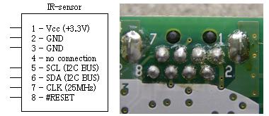
pinout for pixart camera from wiimote
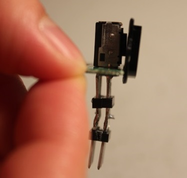
picture of the ir camera
Camera Board
Below is the schematic of the camera board. Instead of using a 3.3V regulator, we decided to use series diode drops because of simplicity. Each diode drop was ~0.4V so we originally thought that 4 diode drops would be sufficient to bring the voltage down to 3.4V. However, we noticed that when we powered on the full circuitry with the camera, the voltage actually drops to 2.8V due to high loading effects. Therefore, instead we decided to only have 2 diode drops so the voltage without the camera was approximately ~4.2V however with the camera, it dropped down to ~3.6V. This was high enough to keep the camera working but not high enough to damage the camera. Another reason why we wanted to be a bit above 3.3V was because of the I2C bus. We had the option of using a dedicated I2C voltage level shifter. However, we realized that if we have the voltage ~3.6V, then a high of 3.6V will also register a high for our 5V microcontroller. Therefore, this would significantly reduce the circuitry needed. We used 2.2k pull-up resistors for the I2C bus to keep the voltage as high as possible (for the 5V microcontroller to register it as a high). The TTL oscillator that we used was actually a 5V component. However, from oscilloscope probe, we found that the actual voltage was only from 0.5V to 4V at the output. Therefore, we just used the direct oscillator output to the CLK input of the IR camera. Also, the reset pin on the IR camera is an active low. For our purposes, we just connected it to 3.3V although it might be more flexible to connect this to an actual I/O on the microcontroller.
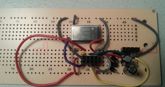
picture of the camera board.
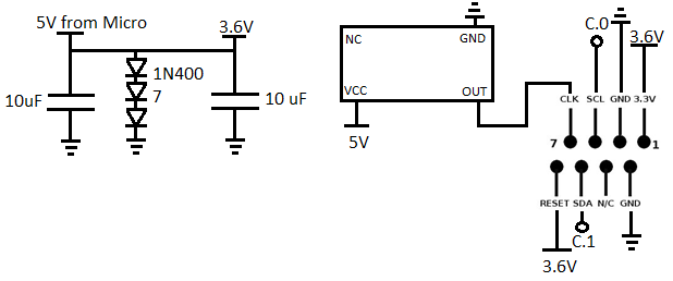
schematic of the camera board.
Wireless RX
Finally, we also have the RF receiver at the client side. We used a very simple long-range 433MHz wireless module for this project. We did not have the time to use an actual RF IC chip which is usually connected using SPI or I2C protocols. Instead, we used a very simple parallel port connection. In other words, this is how the RF receiver worked: there are 4 pins on the transmitter D0, D1, D2, D3. The RF receiver also has 4 pins D0, D1, D2, and D3. If any of the pins on the transmitter goes high, the following pins on the receiver will also go high. Thus, we can easily connect the receiver pins to a microcontroller and do polling to see if any of the pins are high. Depending on the pins, we will know which data was sent. This RF receiver can work on the VCC from anywhere between 5V-9V.
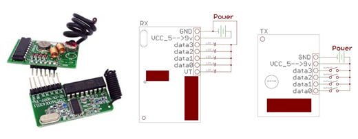
rf RX/TX pair (left), RX pinout (middle), TX pinout (right) (*referenced from RobotShop)
Sensor Board
One of the biggest challenges was to use the sensor correctly. There were few reasons why we had to make a separate circuit board to make the sensor correctly interface with the microcontroller. The first reason is because the camera worked only at 3.3V while the microcontroller was at 5V. There are 2 ways to solve this problem. One is to use an LDO that steps down a 5V to 3.3V. However, we used the other method which was even more simpler: using diodes in series to get the voltage drop that we need. For our case, we used three diodes of each 0.4V drop to get a total of 1.2V drop. This put us at 3.7V. However, after the camera is on, due to the high load, the voltage drops down to approximately 3.5V which is reasonable for the camera. Another reason we needed to create a separate board was to change voltage levels of the I2C. As mentioned above, the camera used 3.3V logic while the microcontroller used 5V logic. Thus, we used pull-up resistors on the I2C line to the 3.7V logic. Fortunately, this was enough to trigger a "high" on the 5V microcontroller. This is because the threshold for high voltage on the micrcontroller is approximately 2.8V so a 3.7V more than enough. Note that we also had to use several big decoupling caps for the 5V and the 3.3V rails because of the high frequency oscillator needed for the camera support circuitry. This helped us stabilize the voltage and remove errors from the I2C communication. Surprisingly, the camera also required a 24 MHz clock. This is because the camera actually captures images at a very high speed to make a 1024x780 pixel image. It actually is only a 128x96 camera but it has built in image processing that uses 8x subpixel analysis to provide a 1024x768 resolution. Therefore, we had to use an external TTL oscillator to provide the 24 MHz clock for the camera. This is also one of the reasons we could not test this circuit on a breadboard because a 24MHz clock cannot oscillate on the high parasitic capacitance of a breadboard.
Remote Side
The remote side circuitry was much simpler than the client side. This is because the remote side has only two objectives: to provide an IR source for the IR camera to track and some user interface buttons that will communicate data wireless to the client. The remote board is supposed to be the board that is in the user's hand. If the person moves the board, the mouse pointer is supposed to move accordingly. This board also has some switches and buttons to select modes and model right/left mouse clicks. At first, we tried to implement a microcontroller which would interface with the switches and the RF modules. However, we later realized that this is an overkill for the application. Instead, we aimed for simplicity. We found that we only need the following options as switches: right mouse click, left mouse click, blackboard mode/whiteboard mode, and scroll mode. In other words, this is only 2 push-button switches and 2 toggle switches. This greatly reduces complexity of introducing a microcontroller and also lowers power (which is a plus because this is a remote and so is powered by a battery). The other important thing on this board were the IR LEDs that the Wiimote tracks.
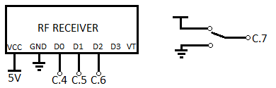
schematic of the remote board
IR Source
We used two 940nm IR LEDs. This is the filter frequency for the IR camera in the Wiimote. We used two IR LEDs in slight different angles such that even if the user moves their hand in wide motions, the IR cam is still able to see one of the two IR LEDs. We also used a 75 ohm resistor in series with the LED. Since we are powering the remote using a 9V battery, which is approximately 120mA through each LED. This can make the resistor quite warm; however we noticed that it was necessary for the LED to be bright for accurate locating by the IR camera.
Wireless TX
Another component on the remote was the RF transmitter. This was operated by the same 9V battery. We decided not to use a microcontroller to control the switching of the sending data instead we used just physical switches that would connect VCC to one of the pins on the RF transmitter This means we had to encode our data into one-hot binary signal. Since we had only 4 pins, we could only encode 4 different data signals. But since we have whiteboard mode/blackboard mode, technically we have a total of 8 data commands to send, 4 in whiteboard mode and 4 in blackboard mode. For this project, this was more than enough encoding needed and so therefore we didn’t need to do anything complicated. We implemented a total of 3 switches: 2 pushbuttons and one toggle switch. The two pushbutton switches acted like the right and left mouse click buttons while the toggle switch turn on/off scrolling mode.
Results top
Speed
The communication speed between the IR camera and the microcontroller depends on the I2C speed. At 400kHz, there was no problems with speed that we could notice. The communication between Matlab and the microcontroller depended mostly on matlab's rate of communication and the microcontroller's response time. The microcontroller's response time was fast enough that no problems could be noticed. In Matlab, we do put intentional pauses to slow down certain points where it may have been too fast a for human to notice or respond to.
As stated in testing, we used matlab's tic and toc function to get latency for the microcontroller to matlab communication as well as the communication latency between the wireless pair. We first found that the time for matlab and the microcontroller to communicate took approximately 38.69 msecs on average. If you run through the commands, it takes about an extra 1ms on average. These numbers are averages and so the average of 1ms for a command is not an exact measure. The communication lag between the wireless pair was around 156.4msecs. This number is also an average and is not an exact number.
Accuracy
The accuracy of the system depended on the accuracy of the IR camera. For the most part the IR camera was able to read out values consistently, but did have a few moments when it would read out a false value. This is because the IR diodes are very directional and the IR camera sometimes cannot see the IR diode. Since we use mousemove this did cause errors when the mouse would jump to the lower left corner in between intentional movmements. It was resolved by filtering out 1/16 of values at the border of the visual field. This is a reduction of 184320/786432 or 23.4% of our visual field. But we now have a very stable reading where we can easily draw a horizontal line with minimal vertical variations and holding the diode in position does not move on the matlab side.
Safety
The only safety issue in our system comes up from the resistors used in series with the IR LED. Because we need a bright light, we use low value resistors which tend to make the resistors hot. To prevent any burns, we can isolate the resistors from human touch with a box. I don't believe this to be an issue because CPU in computers get quite hot but we don't consider then a large enough safety hazard to stop using them.
Interference
We use a wireless module that operates at 433MHz and falls under amateur radio frequency. As we usually do not have such frequencies being used inside buildings, we found no interference when transmitting signals.
Usability
The functionality of this is limited to laptops or computers that are loaded with Matlab. Additionally, there is a limit of how far the B-type cable is for remote placement of the microcontroller unless one wants to use long wires for remote IR camera, which is possible. As it comes from the wiimote, having a moderately long wire for remote placement is not a big deal. Comfort of the system is adequate. Although we do not implement it, a glove or wrist strap for the remote is preferred and not difficult to make.
Conclusions top
Analysis
Though in functionally the project met the requirements we had, there is still something lacking in this which is better range and accuracy. An idea that came to us near the end was to use two IR cameras in conjunction to increase the viewing field of the system and accuracy when the cameras overlapped. Unfortunately, the idea of setting up another I2C connection, taking both data and writing more code seemed too much of a hassle for the time we did have. If we did have another week or two, it definitely was something we would have tried.
Another thing we would like to work on in are some more smoothness and optimization factors. For example, right now we achieved a medicore level of smoothness by cutting out the 1/16th border of the viewing angle. However, even though this can increase smoothness and accuracy, this does reduce the actual viewing area. In a real-life application, whiteboards and blackboards can be very big in size and thus we would need a significant amount of viewing area.
Another issue we had was the remote assembly. An ideal remote would be something that you could place on your hand and so you would not need to actually hold the remote. This way, you could use a chalk and write on the blackboard while the IR camera tracks the IR LEDs fixed on your hands. However, this became an issue in our design because the IR LEDs can sometimes be hidden by the arm. A way to solve this would be to use the IR source directly on the chalk or the whiteboard marker. This way, the IR LED is always visible to the camera and can be tracked accurately.
One more additional option that we can add yet we had no time was for the z dimension measurement. Right now, the IR camera can track the IR LED and give an x-y positioning of the user's hand. However, in some applications, it might be useful to have the z coordinate information too (range from the user to the IR camera). One way to implement this would be to use sonar. We could have a sonar transmitter near the IR camera and the Sonar reflector on the remote. This would provide us the z information which can be used in few applications (such as presentations or etc.)
Conforming to Standards
We had standards for using the UART which we used at 9600 Baud, our I2C which we used at 400KHz, and our wireless transmitter and receiver which ran at 433MHz. The only standard which we must be careful about is the transmission at 433MHz. Looking at FCC part 15.240, we found that as long as it is sent for no longer than 60 seconds. This frequency is often used for garage openers and similar low power devices running at 11000uV/m at 3m distance. Our wireless transmitter adheres to these standards.
Intellectual Property
All of the knowledge required to complete this project comes from what we have learned from classes at Cornell, such as ECE 2100, ECE 3140, and ECE 4760 along with forums online for the Wii Remote IR camera. A portion of our code, specifically the I2Cmaster file and it's use comes from sources we found online and we do not claim any intellectual property on this project.
Ethical Considerations
We have not broken any code of ethics for this project. All of our reference code was code that was found on the internet and we have properly referenced those resources in our usage. Aside from public information on how each of our components work, including people's data of the IR camera, everything else was original and create by us.
Legal Considerations
By FCC standards, our wireless transmitter and receiver pair uses a frequency and our usage falls under amateur radio and does not violate any legal considerations.
Appendices top
File Breakdown
Testing
Final Code
Schematics
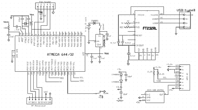
schematic of complete system.
Cost Details
| Part | Vendor | Cost/Unit | Quantity | Total Cost |
|---|---|---|---|---|
| Atmega 1284 | Lab Stock | $5 | 1 | $5 |
| PC Board | Lab Stock | $4 | 1 | $4 |
| White Board | Lab Stock | $6 | 1 | $6 |
| Solder Board | Lab Stock | $2.50 | 1 | $2.50 |
| header pins | Lab Stock | $0.05 | 52 | $2.60 | Power Supply | Lab Stock | $5 | 1 | $5 |
| 9V Battery | $0 | 1 | $0 | |
| Wii Pixart Camera | Amazon | $15.99 | 1 | $15.99 |
| 24 MHz Clock | Digikey | 2.63 | 1 | 2.63 |
| Wireless TX/RX | Robotshop | 18.95 | 1 | 18.95 |
| Push Buttons | Lab Stock | $0 | 1 | $0 |
| Switches | Lab Stock | $0 | 3 | $0 |
| Wires,Resistors,Capacitors | Lab Stock | $0 | many | $0 |
| TOTAL: | $62.67 |
Task Breakdown
Noman Paya
- Soldered the extra 1284P board
- Camera Circuit
- 1284p I2C communication code
Daniel Seo
- Matlab control code
- Matlab and 1284P USB communication code
- Remote Hardware