| Handheld Self-stabilizing Camera Platform |
| ECE 4760 |
| Fall 2013 |
| Project Team Member |
|
| Name: Evan Chen, Geo Xu, Zequn Huang(Joe) |
Project Video: http://www.youtube.com/watch?v=UzbCEqTXwsI&list=PLEB09A7C8641987A8&index=13 |
| Contents |
| 1 | Introduction |
| 1.1 | Sound Bite |
| We created a handheld self-stabilizing camera platform using two high-torque servo motors, a gyroscope, an accelerometer, and a wooden frame. |
| 1.2 | Brief Summary |
| As avid outdoor enthusiasts, we often find ourselves taking action shots of our adventures, only to discover a very shaky and nauseating video of our endeavors at the end of the day. So, for our project, we decided to create a handheld self-stabilizing camera platform. The device will keep a camera in a steady neutral position even if the user is not holding the device steadily while in motion. |
The device consists of a gyroscope and an accelerometer mounted on a platform, allowing the device to accurately determine the pitch and roll of the platform. This platform is connected to two servo motors, where one motor controls the pitch of the platform while the other motor controls the roll. Once the sensors detect a disturbance in the position of the platform, it sends the data to a microcontroller, which then controls the motors to counteract the disturbance and keep the platform in the level position. |
| 2 | High Level Design |
| 2.1 | Rationale for Project Idea |
| Our project idea was to create a handheld camera stabilizer (a gimbal) so that a user can take steady action shots. For example, instead of having a video bounce from side to side as a user walks while shooting a video, a handheld stabilizing platform will allow a user to take a smoother video while the user is in motion. This will help prevent having those shaky and nauseating videos we all too often find ourselves with after recording one of our many adventures. |
| 2.2 | Hardware Overview,Tradeoffs, and Operation |
| As soon as we began working on the hardware design, we had to consider design tradeoffs. In particular, the first issue we discovered was that in order to take into account very minute vibrations, we would probably need piezoelectric motors for precise changes. However, the costs of such motors would put our project well above the $100 threshold. In addition, as we drew up plans for a handheld design, we also realized that we had limited hardware and limited experience in creating such a sensitive and precise device. So, we decided to focus on creating a device that stabilizes a camera from larger scale changes in position. |
|
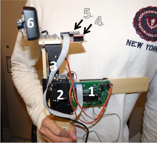
Figure 1: Basic setup for our self-stabilizing platform. (1. Main board containing an ATMega1284p microcontroller with a battery pack mounted behind the handle. 2. Servo motor controlling the roll of the platform. 3. Servo motor controlling pitch of platform. 4. Triple-axis gyroscope. 5. Tripe-axis accelerometer. 6. Webcam attached to platform for testing.) |
As seen in Figure 1, at the core of our design are two servo motors, a main board containing an ATMega1284p microcontroller, a three-axis accelerometer (ADXL345), and a three-axis gyroscope (ITG-3200).? The microcontroller board is attached to an ��L��-shaped wooden frame that allows the user different ways to hold the apparatus.? On the other side of the wooden frame is a battery pack.? The servo motor attached to the main L-shaped wooden frame (component #2 in Figure 1) controls the roll of the platform.? Its shaft is directly screwed into a wooden support frame, which supports the second servo motor (component #3 in Figure 1) that controls the pitch of the platform.? The shaft of the second servo motor is connected to a metal bracket supporting the actual platform that contains the test camera, three-axis accelerometer, and three-axis gyroscope. |
|
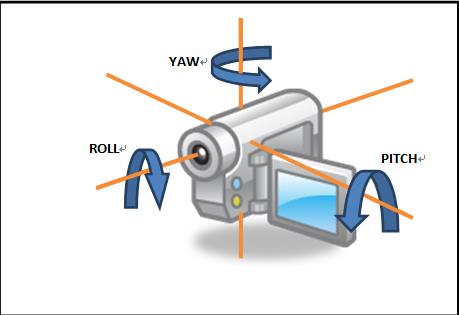
Figure 2: Diagram of pitch, roll, and yaw of camera |
When the device is switched on, the platform is initialized to the neutral position (level to the ground).? Using specific algorithms described later in the software section, the microcontroller detects any changes to the pitch and roll of the platform based on the outputs of both the accelerometer and gyroscope.? Upon detection of a disturbance, the microcontroller adjusts two separate PWM (pulse-width modulation) outputs that control the servo motors, which bring the platform back to the neutral position. |
| 2.3 | Background Math and Software Tradeoffs |
For the platform to quickly respond to any disturbances, a TRT kernel is used to run several functions.? The main functions compute the position of the platform and output an appropriate PWM signal to the servo motors to adjust the position of the platform accordingly. |
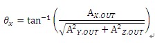
In particular, we use the input data from the gyroscope and accelerometer to determine the pitch and roll of the platform.? The gyroscope outputs degrees per second, so we calculate the current tilt angles by integrating the gyroscope data over time.? The accelerometer outputs acceleration in g��s in three dimensions.? The exact calculations for translating the raw data from the sensors are described in the Software Section.?? With the acceleration values from the sensors, we can then calculate the tilt angles as follows: |
 |
To combine both the accelerometer and gyroscope readings, a second order complimentary filter was used.?? In the simplest form, the complimentary filter is as follows: |
The math for the second order complimentary data is more complicated and is described further in the Software Section. |
To obtain more precise measurements from the sensors, we sample multiple readings and average their values.? However, the more samples we average, the slower our device operates, especially since the data from the gyroscope are long integers.? So, every time we compute the position of the platform, we sample 2 readings from the gyroscope and 4 readings from the accelerometer.? These calculations are computed fast enough to allow the motors to respond frequently enough to produce smooth transitions. |
| 2.4 | Standards |
The main standards that are in use are the SPI protocol used for communicating between the microcontroller and the accelerometer and the I2C protocol used for communicating between the microcontroller and the gyroscope. |
| 2.5 | Existing Patents |
The idea of creating an autonomous self-stabilizing platform is not new.? There have been plenty of commercial products and hobbyist projects that include anything from professional-grade gimbals for movie cameras to makeshift stabilizing platforms for Go-Pro cameras.? Patents currently exist for a variety of stabilized platforms, such as a stabilized camera platform system (US 8125564 B2) and an Autonomous, self leveling, self correcting stabilized platform (US 20070182813 A1).? We also did find some Arduino-based designs that some hobbyist have created, but our particular implementation with our microcontroller and mechanical frame is unique. |
| 3 | Hardware Design |
| 3.1 | Overview |
This project involved a lot of hardware design, including mechanical and electronic hardware. ?The main parts we have in this project are a triple-axis gyroscope, a triple-axis accelerometer, two servo motors, microcontroller, and a wooden frame. ?However, during the design period, we also used other hardware to test and debug, such as the PC serial communication UART, DMM, and oscilloscope. |
| 3.2 | Triple-axis Gyroscope and Triple-axis accelerometer |
| The accelerometer that we use is an Analog Devices ADXL345 triple-axis accelerometer.? It uses the standard SPI protocol and is connected to the corresponding SPI pins in Port B of the ATmega1284p microcontroller.? The gyroscope is an InvenSense ITG-3200 triple-axis gyroscope and uses the standard I2C protocol and is connected to the corresponding pins in Port C of the microcontroller.? Both sensors are soldered onto a board on the platform and have soldered wires connecting them to the MCU board. |
| 3.3 | Servo Motor |
The motors that we use are FEETCH Model #FS5106B high torque servo motors that can rotate a full 180��.? They each come with three connecting pins. ?One is for the PWM wave to control the turning direction and angle, and the other two are for the 5V power supply and ground connection. |
To control the motors, we need to generate a fairly slow PWM for the servo. ?So, we have to use either Timer 1 or Timer 3 PWM modes (which support the Frequency Phase Correct mode that we need) on the microcontroller. ?However, the TRT kernel that we initially had uses Timer 1, and the Timer 3 PWM output pins are needed by the accelerometer. ?So, we currently use Timer 3 for the TRT kernel and Timer 1 for the PWM generation. ?The two channel output pins are PortD4 and PortD5, which are free to use. ?With these servo connections, we can test the servo motors by modifying the PWM signal through PC serial UART communication. |
| 3.4 | Power Supply |
To supply power to both the servo motors and the microcontroller board, we use a circuit that reduces the noise between the different power lines through the use of capacitors, as shown in Figure 4 in the Appendix.? In particular, a battery pack containing 4 AA batteries in series supplies the power.? The operating voltage for our servo motors was 4.8V �C 6V while the operating voltage for ATMega1284P microcontroller is 1.8 �C 5.5V.? Since the battery pack outputs a voltage of 6V, the servo motors could use the power directly.? From there, add a diode to safely supply power to the microcontroller, bringing the voltage to a little more than 5V. |
However, with only diodes and no capacitors, the microcontroller resets when the servo motors attempt to make large and sudden changes upon large perturbations.? This occurs as a result of noise along the power lines.? So, we add capacitors between the power lines, as shown in Figure 4, to reduce noise between the power lines of the servo motor, the microcontroller, and the control lines to the servo motor.?? With the addition of these capacitors, our microcontroller can operate continuously even while the servo motors respond aggressively to large disturbances. |
| 3.5 | Mechanical Frame |
The most complicated part in this project is the mechanical frame and configuration. ?Since we need to control the pitch and roll of the platform, the mechanical frame has to be free to turn in two different directions. ?We found out that it is extremely hard to build the platform at the center of the system with two servos on different side of the platform because of the lack of mechanical tools and frames.? The current setup is shown in Figure 1 and described in the High Level Design section. |
| 3.6 | Connecting the Components |
Finally, we connect every part together to make a self-contained project. ?The gyroscope and the tri-axis accelerometer are placed on the same platform at the very top since they are supposed to measure the pitch and the roll of the platform. ?We solder the socket for the sensors on a PCB and led the connecting wires to the microcontroller, which is mounted on one side of the wood handler. ?We also solder the jumpers for the servo motor onto the MCU board and solder wires connecting to the sensors and the motors to the microcontroller. |
| 4 | Software Design Design |
| 4.1 | Overview |
In this project, our microcontroller program is written for the multitasking kernel Tiny Real Time (TRT) to achieve concurrent execution of several tasks. ?The task layout for the program is listed as follows: |
|
| 4.2 | Serial Communication with PC |
In TRT Task 1, we use pre-defined function fscanf() to get the input string from the UART port, which is the PC keyboard in this case. ?The library and header files needed for using this serial communication function are trtUart.h and trtUart.c which are both given and included in the program. ?Also, two TRT semaphores SEM_RX_ISR_SIGNAL and SEM_STRING_DONE are required for serial communication where the first one is used in UART receiving ISR and the other one is used for detecting whether user typed <enter> key; both of the semaphores are already tuned in the library. ?After getting a valid input, we assigned the input value to corresponding variable such as PID parameters or desired speed of fan. |
| 4.3 | Timer Initializations |
We need a 16-bit timer to generate the PWM outputs that servo motors need, and there are two 16-bit timers in the microcontroller, Timer 1 and Timer 3. ?As the PWM output pin of Timer 3 is used by SPI, here we use Timer 1 to generate the PWM output. ?The Timer 1 is set to Phase and Frequency Correct mode and the prescaler is set to 8 so as to slow down the PWM to 50 Hz. ?Thus, we have to change the UART code and header file to use Timer 3 instead of originally used Timer 1. ?Timer 0 is set to Overflow mode with 64 prescaler to generate 1ms interrupt for test and debug. |
| 4.4 | Use of Shared Variables |
In this program, several global variables are shared between TRT tasks. ?The shared variables we used in this program include P, I, D parameters and calculated tilt angles. ?When one task is reading or modifying a specific variable, the other tasks should not access this variable at the same time in order to avoid potential intervention. ?Therefore, we use an additional semaphore SEM_SHARED in the program to protect shared variables. ?To achieve this, trtWait(SEM_SHARED) is inserted every time before a task uses one or more of these variables and trtSignal(SEM_SHARED) is inserted after the task finishes accessing the variables. |
| 4.5 | PWM Output for Servo Control |
The servo we have basically has three input wires. The brown wire on one side is for ground and the red one in the middle pin should connect to Vcc, which is power supply voltage between 4.8 V to 6V. ?The last orange wire is for the PWM control signal. ?The servo will adjust the shaft position according to the pulse width modulation signal. ?The circuitry of the servo experts a constant 50 Hz PWM signal (period of 20 ms). ?The actual input we send the servo is the width of the high signal duration in the whole period. ?As seen in figure 3, the width of the high signal determines the position of the servo correspondingly. |
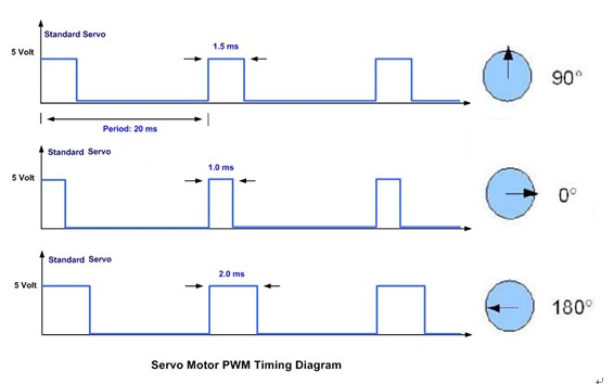 |
Figure 3: Servo Motor PWM Timing Diagram |
| 1.0ms = full right = 0 degree |
| 1.5ms = middle = 90 degree |
| 2.0ms = full left = 180 degree |
The servo motors that we use have full 180-degree rotations. |
We used ATMEGA 1284p Timer 1 to generate the PWM signal. ?Since the proper frequency for the PWM signal is 50 Hz, we cannot use fast PWM mode, which generates a very high frequency signal. ?We currently use the Phase and Frequency Correct mode of Timer T (we switched Timer 3 for the TRT kernel). ?In this mode, we first set the Prescaler N equal to 8, and we calculate our ICR1 (TOP) register value from the equation below. |
| We used ATMEGA 1284p timer1 to generate the PWM signal. Since the proper frequency for the PWM signal is 50 Hz, we cannot use fast PWM mode, which generates a very high frequency signal. We decide to use the Phase and Frequency Correct mode of timer1 (we switched timer3 for the TRT kernel). In this mode, we first set the Prescaler N equal to 8 and we calculate our ICR1 (TOP) register value from the equation below. |
After we set the ICR1 (TOP) value to 20000, the PWM frequency is 50 Hz. ?The OCR1A register value is what determines the width of the high signal.? We can vary OCR1A from 1000 to 2000, which correspond to 10ms and 20ms signal widths. ?For our servo motors, we use more extreme values of 770 to 2300 in order to get a maximum 180�� rotation. |
| 4.6 | PID Calculation |
We tried two approaches to control the servo motor, one is direct angle control and the other is PID control. ?The direct angle control method involves just changing the PWM output to directly let the servo motor rotate a certain angle equal to the current tilt angle in value but opposite in direction. |
The PID control algorithm used in this program is modified from the algorithm used in Lab 4, which is originally a Matlab program where the motor is modeled as a second-order system when being powered and a first-order system when it is coasting. ?In this algorithm, we use the calculated tilt angles as the feedback to the PID. ?The core of the algorithm is the following line of code in the program, |
m_input = pid_p * c_error+ pid_i * pid_integral / 1000 + pid_d * (c_error - c_error_prev); |
where pid_p, pid_i and pid_d are the PID parameters, c_error is difference between current tilt angle and desired angle which is level, c_error_prev is the previous tilt angle from the last PID cycle, and pid_integral is the integral of the previous error terms. |
To achieve a better performance of this PID algorithm on leveling the platform smoothly, we made some modification on the original algorithm. ?First, we put a limitation on the maximum value of the integral term to prevent the cyclic burst of it. ?We also scaled the integral term by 1000-fold smaller to make the pid_i parameter easier to input. ?In addition, we introduce an additional variable SCALE to scale the maximum value of the total PID calculation result m_input to control the change rate of the control PWM signal. ?Finally, the calculation results are mapped to the PWM output registers OCR1A and OCR1B. |
| 4.7 | Calculating Current Tilt Angles |
The accelerometer or the gyroscope along can be used to calculate the tilt angles. ?The output of the gyroscope is degrees per second. ?So to translate this in to degree, we can integrate the gyroscope data over time provide the frequency is high enough. ??The output of the accelerometer is the acceleration (g's) in three dimensions. ?We can then calculate the tilt angles from these data using the following equations: |
The problem with the accelerometer is that it is in general very noise when it is used to measure the gravitational acceleration since the platform may move back and forth. ?The problem with the gyro is that it drifts over time. ?So here we also tried two methods to combine the data from the gyroscope and the accelerometer and then calculate the current tilt angles. ?One method is using the Kalman filter and the other uses the Complimentary filter. |
| 4.7.1 | Kalman Filter |
The Kalman filter operates by producing a statistically optimal estimate of the system state based upon the measurements. ?To do this, it needs to know the noise of the input to the filter, called the measurement noise, and it needs the noise of the system itself, called the process noise. ?To do this, the noise has to be Gaussian distributed and have a mean of zero. ?For us, most of the random noises in our measurements have this characteristic. |
The algorithm of the Kalman filter is too complicated and too long to be written here. ?If you are interested in details, you may see following references: |
http://blog.tkjelectronics.dk/2012/09/a-practical-approach-to-kalman-filter-and-how-to-implement-it/ |
| Normally the code of Kalman filter function has following four steps in a loop: |
|
The code of the Kalman filter we used was originally acquired from SparkFun, and it was then modified to suit our microcontroller and sensors.? |
| 4.7.2 | Complimentary Filter |
The complimentary filter provides another way to combine different sensor data and it is much easier and more intuitive. ?In fact, this filter manages both high-pass and low-pass filters simultaneously. ?The low pass filter filters high frequency signals (such as the accelerometer in the case of vibration) and low pass filters that filter low frequency signals (such as the drift of the gyroscope). ?In its simplest form, the filter is as follows: |
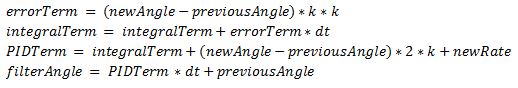
The complimentary filter that we use in our program is a second order filter, which is more complicated. ?The algorithm looks like PID and is given as follows: |
|
| where, k is the time constant, dt is the derivative constant, newAngle is the tilt angle calculated from the accelerometer, and newRate is the angular acceleration calculated from the gyroscope. ?In our code, we made several modifications to this algorithm to make the tilt recovery process faster. ?We introduced a variable to control the proportion of newRate in PIDTerm. ?We also scale errorTerm in integralTerm to make it proportional to the newRate. |
| We finally chose the complimentary filter to calculate the tilt angles as the result from the complementary filter was very close to the one calculated by the Kalman filter. ?Also, the complementary filter is more microprocessor-friendly as it requires a smaller number of floating-point operations. |
| 4.7.3 | Reading Gyroscope Data with I2C |
We use I2C protocol to communicate between the gyroscope and the microcontroller. ?In I2C protocol, the messages are composed of two types of frame: 9-bit address frame and 8-bit data frame. ?The address frame indicates which slave the master�� message is being sent. ?In an address frame, the 7-bit address is clocked out most significant bit (MSB) first, followed by a R/W bit indicating whether this is a read (1) or write (0) operation. ?The 9th bit of the frame is the NACK/ACK bit. ?After the address frame has been sent, data can begin being transmitted. ?The master then simply continues generating clock pulses and the data is be placed on SDA by either the master or the slave, depending on the R/W bit indicating a read or write operation. |
To start a transmission, the master device leaves SCL high and pulls SDA low to initiate the address frame, which is called a start condition. ?This puts all slave devices on notice that a transmission is about to start. ?Then in the transmission process, the data is placed on the SDA line after SCL goes low, and it is sampled after the SCL line goes high. ?Once all the data frames have been sent, the master will generate a stop condition. ?Stop conditions are defined by a low-to-high transition on SDA after a transition of the same type on SCL, with SCL remaining high. |
In ITG-3200 gyroscope, we are interested in the following registers: |
| 0x15, SMPLRT_DIV : The sample rate divider, which is set to 0. |
| 0x16, DLPF_FS: The register decides the digital low pass filter bandwidth, internal sample rate and the gyro full-scale range. ?Here its value is set to 0x1A to have a 1 KHz sample rate and 98 Hz filter bandwidth. ?The gyro range is set to full scale. |
| 0x1D to 0x22: These 6 registers contains the high 8 bits and low 8 bits of the gyroscope outputs of three axis, which are read by the microcontroller continuously. |
| 0x3E, PWR_MGM: Power management register. ?We set the value to 0x80 to reset the device in the initialization and then set to 0x00 to maintain normal work status. |
The lower-level functions including reading and writing registers of ITG-3200 gyroscope are acquired and modified from the SparkFun code. ?In our higher-level functions, we successively read the gyro data several times and use the average value as the result to eliminate the noise. ?We also use the following equation to convert the raw data to angular acceleration: |
| 4.7.4 | Reading Accelerometer Data with SPI |
We use SPI protocol to communicate between the accelerometer and the microcontroller. ?The SPI protocol uses separate clock and data lines, along with a select line to choose which device to talk to. The Slave Select (SS) line is normally held high, which disconnects the slave from the SPI bus. ?In the ADXL345 accelerometer that we used, the SS line is called CS line. ?CS is also the serial port enable line and is controlled by the SPI master. ?This line must go low at the start of a transmission and high at the end of a transmission. ?ADXL345 supports reading or writing multiple bytes in a single transmission by setting the multiple-byte bit MB which is located after the R/W bit in the first byte transfer. |
The maximum SPI clock speed is 5 MHz with 100 pF maximum loading, and the timing scheme follows clock polarity (CPOL) = 1 and clock phase (CPHA) = 1. ?So in the initialization process, we need to set the CPOL bit and CPHA bit to 1 in the SPCR register (which is the SPI Control Register) of Atmega1284p microcontroller. ?We set the SPR1 bit and SPR0 bit to 1 to set the SCK (SPI Clock) frequency to fosc/64, where fosc is the oscillator frequency of the microcontroller. ?We keep the DORD bit with default 0 to use MSB transmission. ?We also set the MSTR bit to 1 to make microcontroller the master in SPI. ?Finally, we set SPE bit to 1 to enable the SPI. ?To read out or write value to SPI data line, we can simply read or write the SPDR register which is the SPI Data Register. |
In ADXL345 accelerometer, we are interested in the following registers: |
0x2D, POWER_CTL : The power saving control register. ?We set the measure bit D3 to 1 to initialize the device. When the measure bit becomes 1, it means the accelerometer has turned into standby mode. |
| 0x32 to 0x37: These 6 registers contains the high 8 bits and low 8 bits of the accelerometer outputs of three axis, which are read by the microcontroller continuously. ?After reading out the data, we need to mask off the upper six bits to convert into 10-bit twos complement numbers. |
The lower-level functions including reading and writing registers of ADXL345 accelerometer are acquired and modified from the SparkFun code. ?In our higher-level functions we successively read the gyro data several times and use the average value as the result to eliminate the noise. ?We also use the following equation to convert the raw data to actual acceleration: |
| 5 | Results of Design |
| 5.1 | Speed of Execution |
We initially had issues with our system responding much too slowly with changes.? The motors would update to a new position approximately 2 times a second, which resulted in slow and rough transitions.? We soon determined the issue to be in the length of time it took for the MCU to compute the tilt angles from the sensor data.? We were taking many samples of the data and running complicated computations on the samples to determine an angle.? So, we had to take fewer samples of the sensor data. |
In addition, depending on the PID values used, the device can transition between +/- 90 degrees in pitch and roll within a second.? However, the faster the transition, the less stable the device becomes.? So, depending on the usage, we tune the PID to the desired outcome.? For example, for applications that require a fast response time, we increase the proportion and derivative parameters of the PID. ?If stability is not a concern, then we are limited in speed by the slew rate of the servo motors. ?For applications that require smoother transitions, we decrease the values for these parameters. |
| 5.2 | Accuracy |
While the platform does remain in a relatively neutral position, the platform does occasionally oscillate back and forth.? This error seems to be caused by multiple sources.? On the software side, since we had to reduce the number of samples taken from the gyroscope and accelerometer, accuracy did suffer where we saw variations in angles of about a degree or two.? In addition, on the hardware side, the bearings on the motor that controls the roll of the platform seem to have become a bit loose.? In particular, its shaft is directly connected to a wooden support that holds the weight of the second motor and the entire platform.? After many trials and tests, the rather heavy loads that we have placed on it have probably caused the bearings to become loose.? Combined, these sources of error make the platform vary at around +/- 2.5�� from the neutral position. |
When tested with a webcam, the platform was able to keep the video oriented in the landscape position as we tilted the apparatus to the extremes of +/- 90�� in both roll and pitch.? However, when the device was held in place without any perturbations, due to the sources of error mentioned previously, the platform would continue to adjust its position up to +/- 2.5�� from the neutral position. |
| 5.3 | Safety |
As this device is not a fine-tuned commercial product, there are some rough areas hardware-wise.? We tried to blunt any potentially sharp corners and pad areas that contained sharp protrusions.? In addition, there is exposed wiring, but they pose little risk to the user.? There is neither high voltage nor current. |
Overall, as long as the platform is not subject to heavy weights, the device seems to hold up rather well. |
| 5.4 | Interference with other people��s designs |
This device does not use any sort of wireless interface that would interfere with other people��s designs. |
| 5.5 | Usability |
The device is designed to be portable, and any user can hold use it in a variety of ways.? It has two handles that a user can use.? At the moment, a camera is screwed onto the platform, so to adapt the platform for other uses, a new platform has to be connected to the device. |
| 6 | Conclusions |
| 6.1 | Analysis of designs |
While the design can be further fine-tuned to create better response time and stability, the basic functionality of a self-stabilizing platform has been achieved.? The device can determine the platform��s angle orientation and can effectively respond to changes in the angles to keep the platform level with the ground. |
At the same time, the device is a representation of many tradeoffs.? To reduce cost, we had to use servo motors instead of piezo-electric motors, which are much more capable in responding to small vibrations.? In addition, many design compromises had to be made when creating the frame for the device.? For example, to reduce overall size, there were very tight tolerances in how things were put together.? If a screw on the platform jutted out just a little too much, the full range of motion of the device would be limited.? In addition, cost and design inexperience made it difficult for us to create a frame and platform more resistant to vibrations. |
In the meantime, there are fixes that can be done with little additional cost.? For example, to reduce the load on the shaft of the motor controlling the roll, we can distribute the load by adding another support panel having a second point of contact on the opposite end of the motor.? In addition, instead of mounting the gyroscope and accelerometer on top of two separate pin socket connectors, we can try placing both together flush against the platform.? This may help increase accuracy in the angle calculations.? Of course, if budget was not an issue, motors with better torque and slew rates can be used instead.? A larger and more refined platform can also be attached so that it can hold a larger variety of cameras and objects. |
| 6.2 | Intellectual Property |
The idea of creating an autonomous self-stabilizing platform is not new.? There have been plenty of commercial products and hobbyist projects that include anything from professional-grade gimbals for movie cameras to makeshift stabilizing platforms or Go-Pro cameras.? Patents currently exist for a variety of stabilized platforms, such as a stabilized camera platform system (US 8125564 B2) and an Autonomous, self leveling, self correcting stabilized platform (US 20070182813 A1).? We also did find some Adruino-based designs that some hobbyist have created, but our particular implementation with our microcontroller and mechanical frame is unique.? The design we did ultimately got our inspiration from came from the following youtube video: http://www.youtube.com/watch?v=T0SFAdPUUYs. |
In addition, as a starting point, we used code that was provided to us in Lab 4 for the PID, TRT, and UART.? We also looked up filter algorithms and referenced sample code as mentioned in the software sections, such as code for basic functions to communicate with the accelerometer and gyroscope provided on the SparkFun website. |
| 6.3 | Ethical Considerations |
From the safety point of view, we made sure the device would not cause any harm to the user.? Any potentially sharp corners and protruding edges have been blunted or padded.? In addition, the operating voltages and currents are relatively low.? The product also does not interfere with any other devices as it does not transmit anything wirelessly. |
Furthermore, throughout the process, we made sure we worked within our bounds.? We made sure to never go above the $100 budget even though that would have allowed us access to better hardware.? From the budget, we were able to improvise and learn in many ways.? Rather than relying on purchasing stabilizing brackets and platforms, we made our own. |
In addition, the goal of the project was to create a stabilizing platform that any person can use.? While its original purpose was to be a self-stabilizing platform designed to take steady shots, after further testing and evaluation of the design, we have determined that jitter and vibrations are inherent in the design.? So, we recommend it as a stabilizing platform for video recording.? It can keep a camera or any other object oriented in a relatively level position in relation to ground level, albeit with some vibrations.? With these limitations, we are open to any suggestions for improvement. |
| 7 | Appendix |
| 7.1 | Schematics |
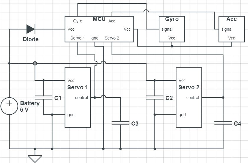 |
Figure 4: Schematic of overall connections and power lines |
| 7.2 | Cost Details |
Part |
Vendor |
Cost |
Mega1284 |
Provided by class |
$5 |
Gyroscope (ITG-3200) |
Ebay |
$12.95 |
Accelerometer (ADXL345) |
SparkFun |
$19.95 |
Wood and Hardware Mounts |
Lowes |
$20 |
2 x Servo Motors |
SparkFun |
2 x $12.95 |
Batteries and Battery Pack |
Found in home and class |
$5 |
Total |
|
$88.80 |
| 7.3 | Task of each team member |
| Geo figured out how to interface with the gyroscope and accelerometer, and he also reviewed the math needed to compute the tilt angles. He was the software lead. |
| Joe and Evan worked on the hardware aspects of the project. The determined the motor, platform, and frame configurations and put the device together. |
| Evan combined the code for the sensors, PID, and TRT. |
| Joe took the lead in figuring out how to wire all the electronics. |
| All members were involved in testing the device and everyone contributed to writing the report. |
| Joe also converted the report to be able to be put on website. |
| 7.4 | References |
Data Sheets |
ATMega1284p Data Sheet: http://www.atmel.com/images/doc8059.pdf |
ITG-3200 Gyroscope Datasheet: https://www.sparkfun.com/datasheets/Sensors/Gyro/PS-ITG-3200-00-01.4.pdf |
ADXL345 Accelerometer Datasheet: https://www.sparkfun.com/datasheets/Sensors/Accelerometer/ADXL345.pdf |
FEETECH Servo Motor: http://dlnmh9ip6v2uc.cloudfront.net/datasheets/Robotics/FS5106B%20specs.pdf |
Algorithms |
Complimentary Filter: http://web.mit.edu/scolton/www/filter.pdf |
Kalman Filter: http://blog.tkjelectronics.dk/2012/09/a-practical-approach-to-kalman-filter-and-how-to-implement-it/ |
Vendor and Code |
PID and Motor Control: http://people.ece.cornell.edu/land/courses/ece4760/labs/f2013/lab4.html |
TRT Kernel: http://people.ece.cornell.edu/land/courses/ece4760/TinyRealTime/index.html |
Accelerometer: https://www.sparkfun.com/products/9836 |
Gyroscope: https://www.sparkfun.com/products/9793 |
Servo Motors: https://www.sparkfun.com/products/11965. |
| 7.5 |
| final_code_v5.c |