Introduction
Smart home technology has been surging in popularity over the past decade. According to a recent poll, 46% of consumers believe that it is important that their current or next home has smart technology. Many smart home technologies are expensive to implement and require a third-party company to monitor and support the system. We decided to design a low-budget system that the consumer can build for under $100.
Our project was broken into a few different subsystems that we felt were important in a home automation system. The first subsystem was a motion detector that utilized a passive infrared sensor. This subsystem also included a buzzer and 555 timer that raises an alarm when motion is detected. The second subsystem was a smoke detector that is able to detect propane, hydrogen, methane, butane and smoke. We chose this sensor because we felt these are the most common hazardous gasses found in one's home. Additionally, our system included small-scale climate control that included a temperature sensor and Peltier thermoelectric device. To implement the wireless technology, all subsystems interacted with our microcontroller, which then communicated with the user through RF transmitters. With the RF transmitters, the user is able to poll the status of the home, receive intruder and smoke alerts, and set the home's temperature from a computer up to 100 meters away. Due to the multitasking nature of our project, we used a multitasking kernel.
High Level Design
Rationale and Sources
Our goal for this final project was to design something that could be useful in everyday life. Many consumers are exploring various smart home technologies to make their lives easier. What many consumers do not know is that they do not need to purchase an expensive third-party smart home system. Many of the most useful smart home technologies can be built cheaply by the consumer. We determined that a motion detector, smoke detector, and thermostat are a few of the most necessary technologies that comprise a smart home.
In this day in age, everything is connected. The "internet of things" is a popular concept to interconnect all aspects of one's life. A simple smart home technology would required the user to interact with the system from a single location, which would be whereever the device is placed. With the increase in popularity of smart phones and wireless communication, we believed that a huge benefit of a smart home system is the ability to interact with your home from any location. This is the rationale behind making our Smart Sitter wireless.
For the climate control system, we explored various ways to adjust the temperature surrounding our system. Using a heating coil and fan, we could have increased the temperature around our system, but we would only be able to cool it back down to room temperature using the fan. We knew that designing an air conditioner and compressor would not be practical, or cheap. Exploring alternate technologies, we were introduced to Peltier thermoelectric devices. This solid-state active heat pump transfers heat from one side of the device to the other, using electrical energy. The hot and cold sides can be varied by changing the direction of the current through the device. Using the Peltier device we are able to achieve temperatures lower than room temperature.
Logical Structure
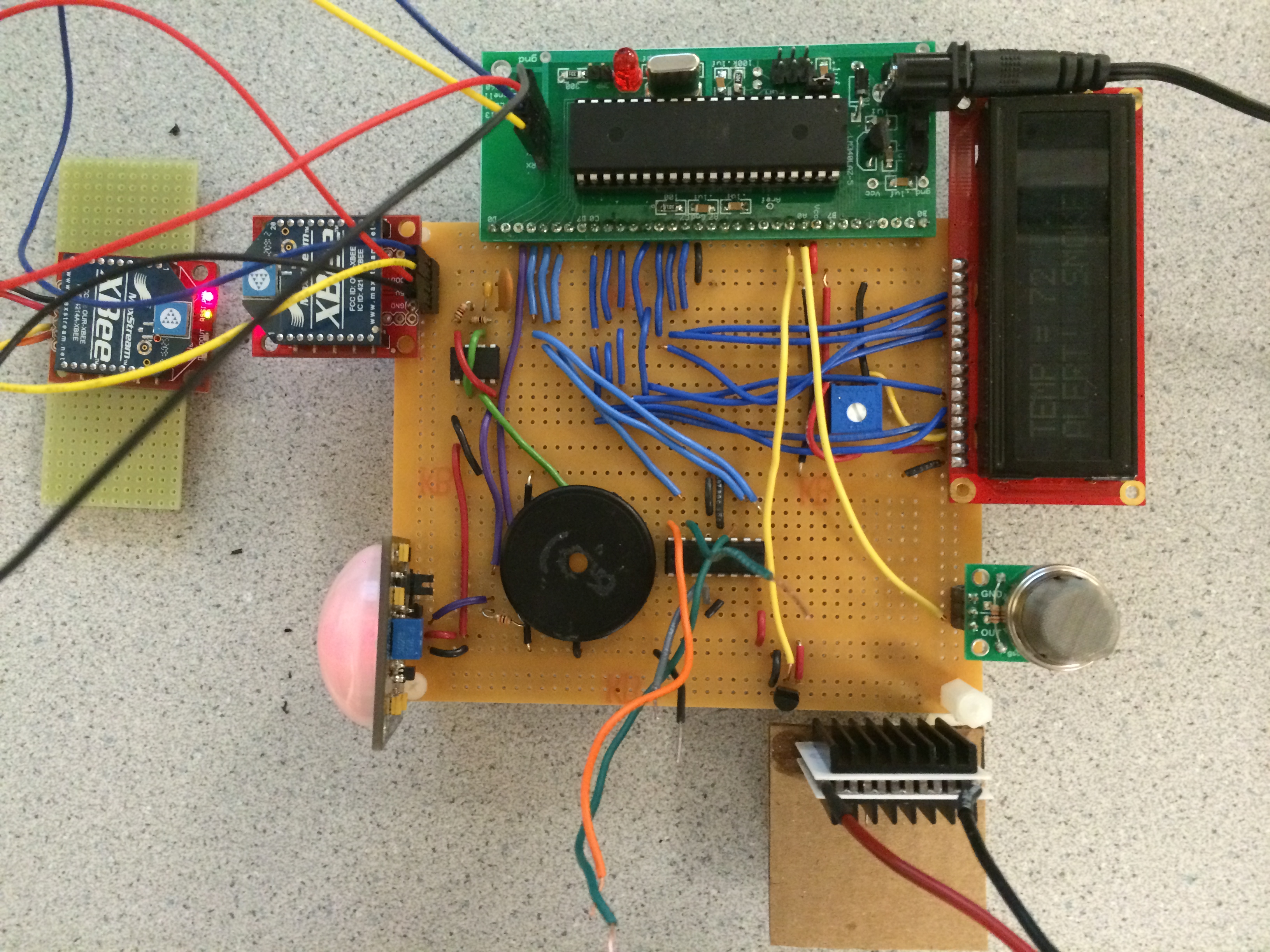
The logical structure of our system can be broken up into four main subsystems, which all connect to the MCU: PIR motion sensor, temperature sensor, thermoelectric generator, and smoke detector. On a higher level, our system interacts with the user through RF transmitters on the MCU and the user's computer. The split nature of our project allowed us to design, test, and debug each subsystem separately in both hardware and software. The block diagram below illustrates the complete structure of our system.
System Block Diagram
Each subsystem can be broken down into smaller hardware and software components. In software, each subsystem has its own task running in the Tiny Real Time multitasking kernel. Each task contains the repsective code that each subsystem needs to operate correctly. Tasks are given deadline and release times and include semaphore locks for sensitive variables that are used in other tasks.
As shown in the block diagram, the motion sensor, temperature sensor, and smoke detector all send information to the MCU. The MCU then processes this information and depending on the data it receives, sets the LCD display and sends data to the RF transmitter, which is then received on the user's computer. To simplify our design, the buzzer was implemented entirely in hardware and is dependent on the output of the motion sensor. To operate the climate control subsystem, the MCU receives the desired temperature from the RF transmitter connected to the user's computer. It then determines whether it needs to make the area's temperature warmer or colder based on data from the temperature sensor and sets the direction of the current through the Peltier TEC accordingly.
Hardware and Software Tradeoffs
We decided to implement the more complex parts of the system in software. Because we were interested in creating an entire working system within our budget and time constraint, some of the complex hardware components, like the PIR motion sensor, H bridge, and timer, were purchased prebuilt. This allowed us to focus on creating an interactive system through multitasking software. Throughout our design process, there were not too many situations where we forced to make hardware/software trade-offs. However, choosing the analog instead of the digital temperature sensor was one instance where we did make a trade off. Though our original plan was to implement a digital temperature sensor, when we went to implement it we found the hardware quite difficult to understand and use properly. For this reason, we chose to implement the analog sensor instead. This increased the software complexity of the temperature sensor unit, but we felt the added complexity in software was more manageable than the added complexity in hardware.
Standards
The smoke detector that we purchased and integrating into our product complies with the Underwriters Laboratory Specification UL217 and UL268. UL 268 "sets forth requirements for smoke detectors and mechanical guards to be employed in ordinary indoor locations in accordance with the National Fire Alarm Code, NFPA 72." UL 217 "covers requirements cover electrically operated single and multiple station smoke alarms intended for open area protection in indoor locations of residential units in accordance with the National Fire Alarm Code, NFPA 72, smoke alarms intended for use in recreational vehicles in accordance with the Standard for Recreational Vehicles, NFPA 501C, smoke alarms intended for use in recreational boats in accordance with the Fire Protection Standard for Pleasure and Commercial Motor Craft NFPA 302, smoke alarms intended for use in detached one- and two-family dwellings and townhouses in accordance with the International Residential Code and portable smoke alarms used as "travel" alarms."
Our C code follows the American National Standards Institute (ANSI) C language standards.
The XBee transmitter and receiver devices we used in this project followed the standards set by the FCC.
Intellectual Property
Our utilizes the Tiny Real Time multitasking kernel that was developed by Dan Henriksson and Anton Cervin. However, their operating system is open for our use. We also used Roger Meier's CoolTerm program as the serial communication interface. His program is freeware that are open source and available for use. Other than the multitasking kernel and serial communication interface, our project does not contain anything else that may infringe on intellectual property or patents of others. Passive infrared sensing, resistance-based smoke detection, and Peltier TEC's are not under copyright and are used in many commercially available systems that are available for purchase for any consumer.
Program/Hardware Design
Passive Infrared Motion Sensor
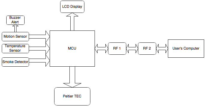
The motion detector subsystem was implemented using a Passive Infrared (PIR) motion sensor that output a digital high signal (5V) when motion was detected to the MCU. Using this digital input signal, we sent an alert signal to the LCD that displayed "ALERT!" until the alert signal from the motion sensor was no longer triggered. The alert signal was also sent wirelessly using the XBee to the user's PC. The only drawback of the motion sensor was the 40 seconds it took to warm up and learn its environment. The 5 volt high signal from the motion sensor was also used to trigger a buzzer to signal an intruder. A 555 timer was used to output a 2kHz frequency for the buzzer. The PIR subsystem is shown in the image below.
PIR Motion Sensor and Buzzer Subsystem
Climate Control and Temperature Sensor
The climate control and temperature subsystems interacted directly with each other. For the temperature sensor, we used the LM34 analog temperature sensor that had used analog voltages of 10mV/degree fahrenheit. This convenient step in voltage allowed us to use the internal ADC of our MCU to convert the analog voltage value outputted from the temperature sensor into a fahrenheit value. the ADC value was left-shifted to enable an 8-bit result, and the internal reference of 2.56V was used. From here, the termperature value was used by the MCU to implement climate control with the Peltier TEC and send temperature data to the user's computer through the XBee RF modules.
The Peltier device is an thermoelectric solid-state active heat pump, which transfers heat from one side of the device to the other when a current is run through the device. When the direction of the current switches, the hot and cold sides switch. Thus, we could implement small-scale climate control by heating the side of the Peltier device closest to the temperature sensor when the user wanted to increase the temperature, and change the direction of the current through the device when the user wanted to decrease the temperature. Changing the direction of the current now makes the hot side cold, which cools down the temperature sensor. Because we needed two different current directions, we used an H Bridge that can switch the direction of the current running through the Peltier device. The Peltier device was driven by a separate power source to supply 1 A of current because this output current is unachievable by the MCU.
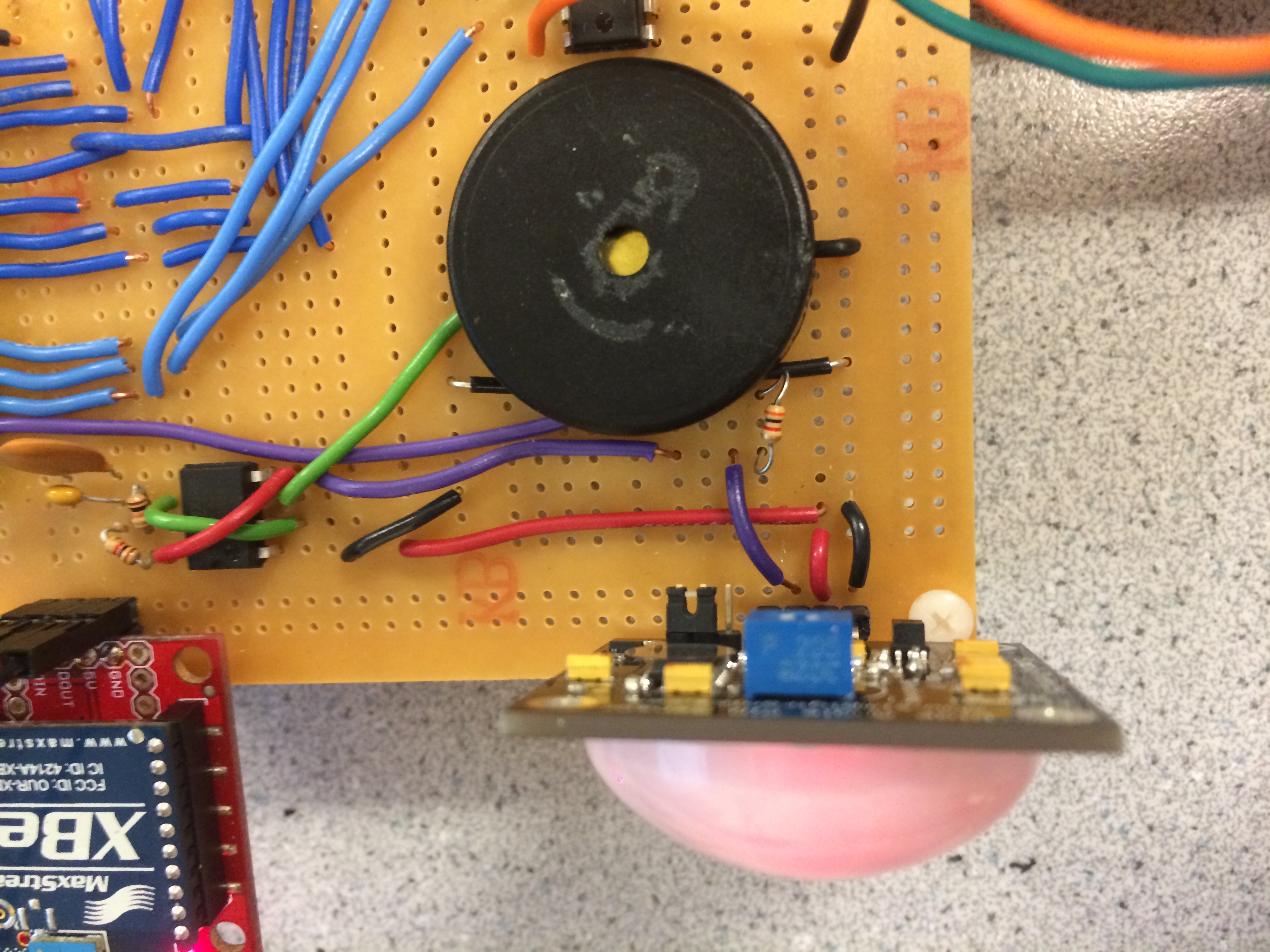
To control the system's temperature, the user inputs a command into the serial communication interface on his computer followed by the desired temperature. The XBee transmits this information to the MCU's XBee, which then sends it to the UART interface in the MCU. Based on the desired temperature value read by the MCU, the MCU will check if the current temperature is higher or lower than the desired temperature. Once this is determined, the enable value and appropriate current direction values are set on the H Bridge, which then allow current to flow through the Peltier device, cooling or heating the temperature sensor. The climate control and temperature sensor subsystems are shown below.
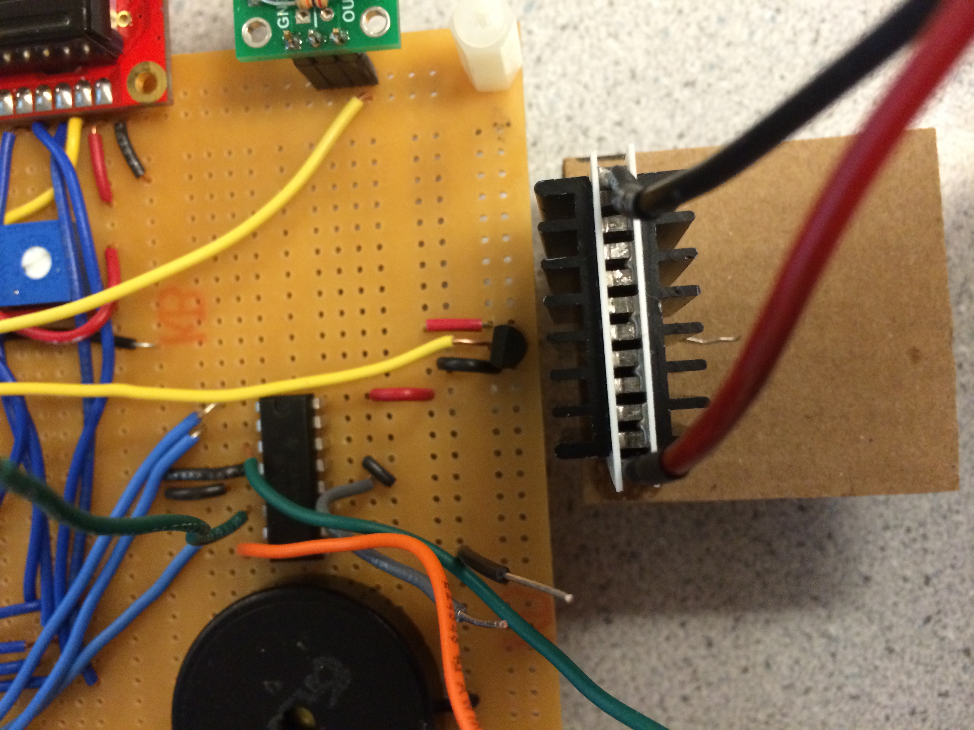
Peltier TEC, Analog Temperature Sensor, and H Bridge
Smoke Detector
The smoke sensor subsystem was implemented using a MQ-2 flammable gas and smoke sensor. The sensor measures the flammable gas concentrations from 300 to 10,000 ppm. It is highly sensitive to LPG, Propane, and Hydrogen. The sensor converts a change in conductivity to an output signal of gas concentration. The major drawback to the hardware implemented in this subsystem was the 48 hour warm up period. We sent the output of the gas concentration to one of the analog to digital output pins of the MCU. Then, through trial and error, we determined the output level that indicated a combustible gas was detected. When that threshold was reached, a smoke alert signal was set to high. This signal triggered a "SMOKE!" message on the LCD and wirelessly communicated to the user's PC that smoke had been detected. The smoke detector is shown below.
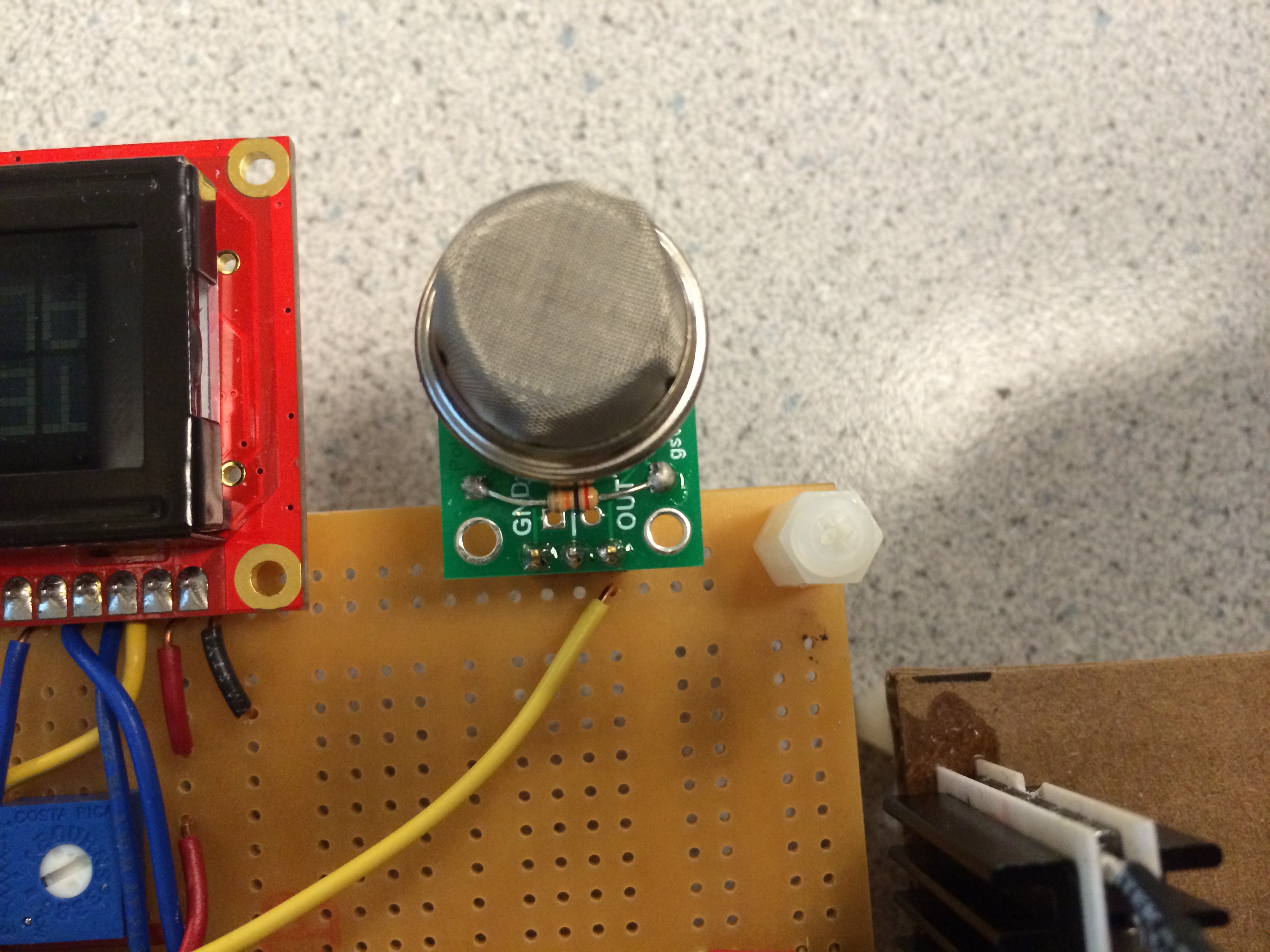
Smoke Sensor
LCD and UART Interfaces
For the updating the UART interface and the LCD display when there is an intruder detected by the motion sensor or smoke detected by smoke sensor, it was necessary to debounce the respective alert signals. The purpose of debouncing the alert signals was to have one single display for each alert that stayed on the LCD screen for an appropriate amount of time. The two alert signals were debounced using finite state machine. The two simple finite state machines for smoke and motion sensors waited for the alert signal from either the smoke sensor or the motion sensor outputs. Once a high signal is sensed, it changes a variable to that tells the LCD and UART to display the appropriate alert message. It then stalls in the next state until the output of the smoke or motion sensor goes low. This stalling stage allows enough time for the signal to be displayed and read by the user and ensures that the alert is triggered only one time by each signal from the sensor. Once the output goes low, the alert variable is changed to 0 and the state machine goes back to waiting for a signal from the sensor. The UART also used the two finite state machines to display only one alert message for each trigger of the sensor.
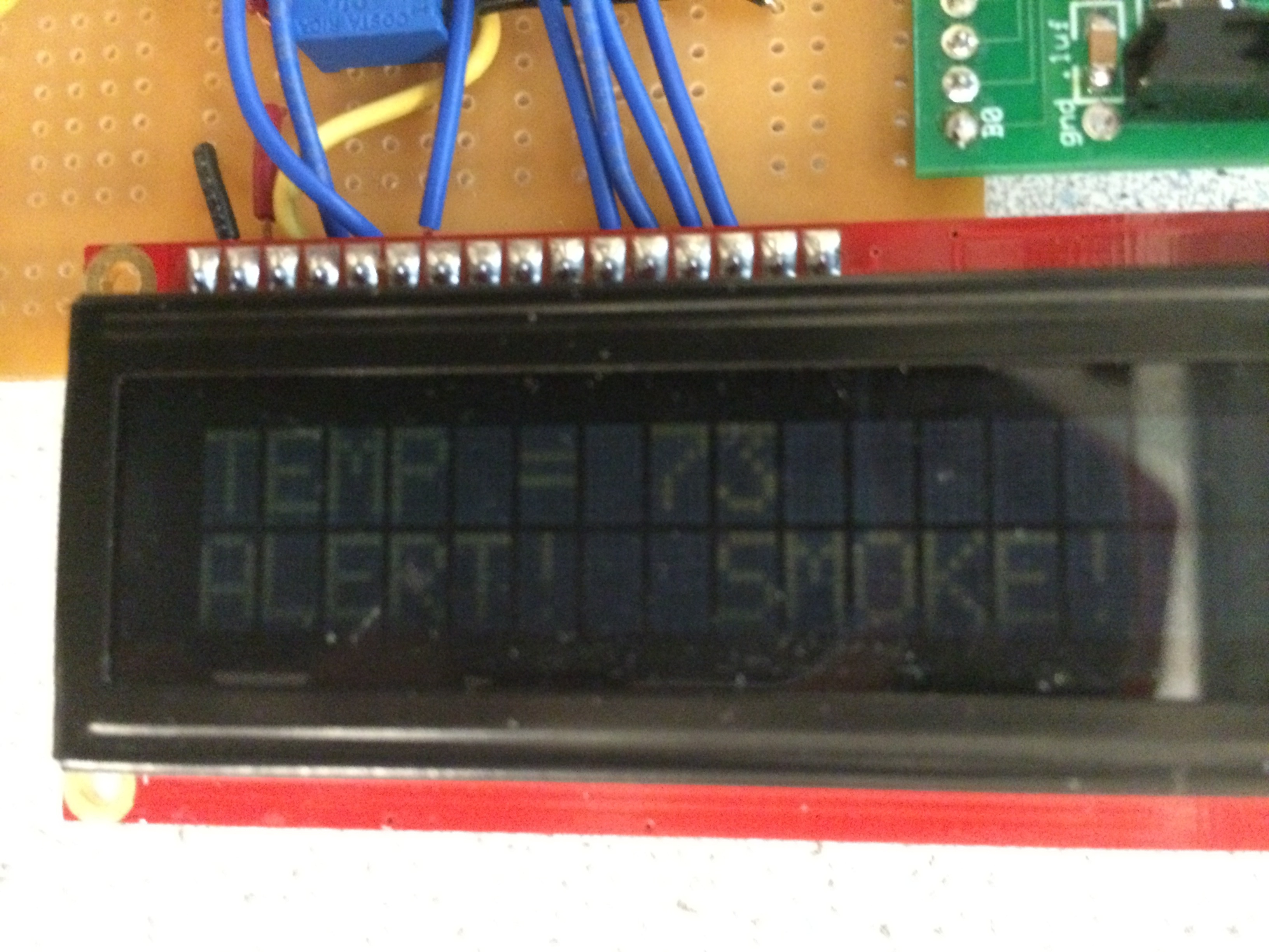
LCD Display Showing Temperature, Smoke Alert, and Intruder Alert

System FSM for UART and LCD Communication
Wireless Communication
In order to make our system wireless, we implemented RF communication between the user's computer and the main unit using two XBee RF Modules that follow the 802.15.4 communication protocol. These two modules transmit data packets to each other by serial communication. Through their serial ports, they can communicate with any logic and voltage compatible UART interface. The Xbee's were wired together as shown below, with one Xbee receiving Data In information from the MCU and the other Xbee sending Data In information to the user's computer.
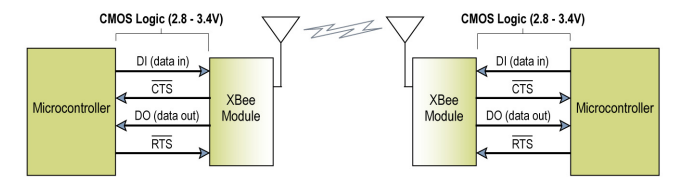
XBee Block Diagram
Our XBee modules were set up following the example from the Digi XBee Examples and Guides page, which explained how to issue system commands to the Xbee to set each module's address and function in the radio network. We followed the example to set up a two module network where there is only point-to-point communication. However, the XBee's also allow for point-to-multipoint communication if the user's application requires multiple system units communicating with the user's computer. There are a finite number of addresses available for the XBee's to occupy; however, we did not need to worry about interference in our design because no other XBee's were transmitting in our network area. If the user implements many XBee modules, he must be careful to not duplicate module addresses because interference will likely follow.
Our XBee RF modules were able to send communicate data and commands between the MCU and user's computer. The user was able to set the desired temperature for the small-scale climate control subsystem by issuing a command and desired temperature in Fahrenheit. The XBee's then transmitted this data to the MCU, which was then responsible for changing the system's temperature. All motion detection and smoke detection alerts were automatically sent from the MCU to the user's computer using the XBee's. This made sure that the user was always informed of what was occuring in the home. In addition, if the user was curious about the current status of the home, the user could issue a status command. This command told the MCU to send the system's current temperature, motion detection status, and smoke detection status to the user's computer.
Results and Testing
Passive Infrared Motion Sensor
Results
The PIR Motion Sensor that we implemented was very accurate and responded to motion in less than 0.5 seconds to any change in infrared radiation detected in 180 degrees and up to 30 feet away from the device. When the alert was triggered, the alert message was displayed on the LCD and the PC in under about half a second. The PIR device also has a trimpot adjustable sensitivity to adjust the sensitivity to the user's needs.
Testing
The Motion Detector subsystem was the first subsystem that we implemented and we were able to test it using an incremental design approach. We first simply powered up the PIR sensor and determined that we were getting high signal sent to the MCU when motion was detected. Next, we sent the alert signal to the LCD screen and worked at debouncing the alert signal until it was only displayed once each time motion was detected. We then worked on the buzzer circuit and tested the buzzer without the motion sensor until we were able to achieve the appropriate frequency. Finally, we wired the motion sensor's output to the buzzer and the MCU and determined that the LCD and buzzer worked in parallel.
Climate Control and Temperature Sensor
Results
For the temperature sensor without activating the peltier device, we achieved about +/-1 degree Fahrenheit accuracy. The accuracy of our temperature sensor was limited by the resolution of the MCU's ADC. Because we used only 8-bits of the ADC output, our temperature readings were not as accurate as they could have been. However, we believed that an accuracy of +/-1 degree Fahrenheit was accurate enough for our application needs.
The Peltier device gave varied results. When increasing the temperature of our system, our Peltier device increased the temperature sensor's temperature by about 1 degree Fahrenheit per second when keeping the temperature around room temperature. When we attempted to achieve temperatures above 15 degrees Fahrenheit of room temperature, the Peltier device could no longer increase the temperature of our system. Because of our power source constraints, we could only draw 1A of current through the Peltier device, which limits the amount of heat difference between the two sides. This will place a limit on how warm or cool we can make the Peltier device. Also, because our system is open to the outside environment, we cannot heat the entire room with such a small device. We understood this drawback going into the project and mostly used the Peltier as a proof-of-concept that the system can control a user's home climate if the device is connected to the home's heating and cooling systems.
Another drawback of the Peltier device was attempting to cool the system after heating it above room temperature. Although heat sinks were attached to both sides of the Peltier device to achieve better heating and cooling, it was not enough to bring the system temperature down very quickly. Even though the cold side of the Peltier device was facing the temperature sensor during a cool-down stage, the hot side of the Peltier device was close enough to the temperature sensor to affect its reading. In a more commercial thermoelectric cooling system, complex heat sink systems are required to effectively remove heat from the Peltier device. Although Peltier thermoelectric generators are not efficient enough for home use currently, it was an interesting concept to explore in our project.
Testing
To test the climate control and temperature subsystems, we took data readings from our MCU and compared them to the actual measured temperatures in the room and on our temperature sensor. We also analyzed the time it took for the Peltier device to heat and cool the temperature sensor after the user set a desired climate temperature.
Smoke Detector
Results
The smoke sensor was a bit inconsistent in output values indicative of a combustible gas. This inconsistency may lie in the rather substantial warm up time required of the sensor. Before we allowed for proper warm up time, we were unable to achieve consistent output values to trigger the smoke alert signal. Even when the smoke detector was allowed 48 hours to warm up, the threshold continued to vary to a marginal extent. Once the appropriate threshold was reached indicating smoke detected, the LCD and PC displayed their alert signals within 1 second.
Testing
Testing the smoke detector was again done incrementally. Initially, we observed the output from the smoke detector sent to the analog to digital converter by simply displaying the raw input signal. After determining that the raw input was changing when exposed to flammable gas, we moved on to implementing the smoke alert signal. We tested smoke alert signal using the LCD screen message and smoke alert message on the PC in parallel. Final testing involved implementing the smoke sensor along with the temperature sensor as they both required analog to digital inputs.
Wireless Communication Subsystem
Results
The XBee RF Modules worked very well for our system's application requirements. We were able to achieve communication between the user's computer and our device from almost 100 meters away. The UART serialization of the XBee modules made the communication straight-forward to implement because our MCU already uses UART serialization to commuicate with a computer via a program like PuTTY. Placing the XBee modules into the communication interface did slightly increase the delay between something occuring in the system and the respective alert or message appearing on the user's computer screen. This delay was about a quarter second to half a second, which we determined was acceptable for the application.
Using RF communication introduces the possibility of interference with other devices on the same frequency. Our XBee modules operate within the ISM 2.4 GHz frequency band. If there are other devices operating within this same band, especially other XBee's with the same sender or receiver address as ours, interference can occur between the devices. This interference can corrupt the data flow between the user's computer and the system, which may set an incorrect temperature for the climate-control or issue invalid system alerts.
Testing
To test the XBee modules, we followed the example listed in the design section above. This example created an instant-messaging application between the XBee's wired to two different computers. We decided that this example was similar to how we intended to set up our own XBee's. Once we succeeded in creating a working instant-messaging application, we transferred this design to our system and altered it for our own needs.
Conclusion
Analysis
We were very pleased with how our designed worked out. Each subsystem worked as intended and the multitasking kernel allowed us to have all the subsystems interacting with each other. We also were happy that the XBee RF modules performed as intended, at least over a short range. We originally wanted to implement the wireless communication in our system through bluetooth technology. With bluetooth, we would be able to create a phone application that the user can employ to interact with the system without having to be at a computer. With the popularity of smart phones, we believed this would have been an exciting addition to our project. Had we more time or budget for the bluetooth devices, we would definitely have implemented the bluetooth communication and a simple Android phone application.
We also had originally planned to implement more subsystems in our Smart Sitter. The beauty of our system is that additional sensors or controls can be added to the hardware and multitasking kernel in a straightforward manner. We thought that designing an automatic water pump to autonomously water a user's plants when the soil was to dry would be a very useful system in a smart home. Especially in areas afflicted with drought, an automatic water pump can be used to hydrate plants only when the soil actually needs it, thus avoiding wasteful overwatering.
Conformation to Standards and Legal Considerations
Our project followed all required standards layed out in the standards section above. Some of these standards, like those relating to wireless communication, are important in order to ensure proper use of a wireless system. As with all wireless systems, there is the possibility of hacking, which can cause undesirable use of the system. Another standard required to follow for wireless communication is the FCC standard for legal considerations. We conformed to this standard by using the XBee RF modules, which are approved by the FCC for use. We also followed all other standards listed in the earlier standards section.
Ethics
While completing our project, we were mindful of the IEEE code of ethics and made sure to abide by it. There were a few parts of the code of ethics that were particularly relevant to our project. We increased our technical competence- we gained quite a variety of new technical skills that we will carry with us into our future as electrical engineers. In particular, we strengthened our knowledge of microcontrollers, various sensor devices, and C programming. We did our best to learn the most we could about the components in our project through various resources at our disposal. We kept in mind safety considerations when completing each aspect of a project and never attempted anything during testing that would endanger ourselves or those around us. This was important particularly when testing the smoke sensor as we had to find a way to test it without an open flame in the lab. We sought and accepted criticism for our technical work. There is no way we would have achieved the results we were able to achieve without major help from our professor and various teaching assistants. We also assisted each other in our professional development as electrical engineers and held each other accountable to the IEEE code of ethics.
Intellectual Property Considerations
Our project reused the multitasking kernel code provided by Dan Henriksson and Anton Cervin's Tiny Real Time operating system. We also used setup code for the XBee's that was given as examples on Digi's website. Also, because we have used the ADC before on our MCU, we reused the ADC code from that project to implement the smoke detector and temperature sensor software portions. All other portions of our software were implemented by ourselves either by past projects or from scratch. No reverse engineering or non-disclosure forms were necessary to implement our project. We believe that there are not possibilities of patents for our system because there are not any new technologies used. However, there are possibilities of publication especially in the domain of do-it-yourself smart home projects. Many smart home hobby projects that we saw while researching online did not discuss implementing all the subsystems using a multitasking kernel or wireless communication. Our project brings many small subprojects together in an organized fashion.
Appendix A: Code and Schematics
Program Listing
Circuit Schematic

Circuit Schematic
Appendix B: Budget

Project Budget
Appendix C: Task Distributions
All software and hardware design and implementation was done by both Anne Billig and Andrew Palmer equally. Each student worked in the lab together on each subsystem.
Website html and css code was done by Andrew Palmer
Schematics and block diagrams were made by Anne Billig
Writing the content of the website was split equally by Anne Billig and Andrew Palmer