ECE 4760 Final Project: CPR Training Dummy on AVR
Dec 8th, 2014
Rameez Qurashi (rq35)
Sungjoon Park (sp2283)
Haoyuan Chen (hc576)
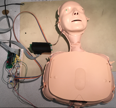
Finished
prototype dummy
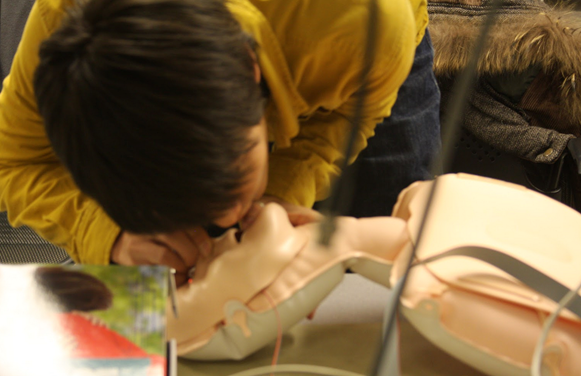
Sungjoon
Park, M. Eng. Student, testing the manikin
Project Demonstration Video on YouTube
Contents
Introduction
For
our ECE 4760 final project, we implemented an interactive CPR training dummy
which can coach the trainees through the CPR process with a LCD to display
instructions.
The
prototype CPR training dummy built is a budget-friendly one that contains a
re-programmable Atmel ATmega1284 microcontroller and other hardware components
so that it can interact with trainees in real time through a LCD display and
two RGB LEDs during the training process to realize a more efficient training
process. This CPR training dummy will provide a great education to anyone who
is capable of performing CPR. This original design achieves the functionality
of commercially available CPR training dummies in the current market with a
more interactive and intuitive user interface, at an affordable price.
According to the standard CPR process, we break down the process into two
parts, the chest compressions and airway/ventilation. Converting analog signals
to digital signals, the dummy will check if the correct number of chest
compressions is given with the correct frequency and correct pressure in the
correct area of the chest. It will also check if breaths are given at the right
time with a clear airway with the nose of the dummy pinched. A tilt switch is
used to make sure the user has the manikin’s chin is tilted upwards to ensure
the airway is clear before giving breaths. The user interface composed by the
LCD display and the RGB LEDs will tell the user which step in the CPR process
they are on (chest compressions or airway/breathing) and whether they are
performing the process correctly. Two modes of CPR process are provided -- a
practice mode and a real mode. The practice mode will guide the trainees
through the CPR process step by step and the real mode serves as a “test” to
make sure the trainees can act accurately and fluently in the CPR process in
reality.
High Level Design
·
Patents
Rationale
While
the CPR serves as an essential part of emergency aid to help save thousands of
lives every year, the CPR training classes are not available to everyone due to
limited resources and the high expenses of the training dummies. Typically, a
simple CPR training dummy without any functionality to guide the users costs
more than a hundred dollars in the current market. Besides the dummy, the cost
to run training classes to tutor trainees could be costly as well. We decided
to design a budget-friendly CPR training dummy that could interactively guide
trainees through the CPR process. As there are sensors to detect user actions,
an LCD to display instructions and two LEDs to indicate whether a user is
performing the correct actions, the user can learn how to do CPR without an
actual trainer, thus eliminating extra cost. The dummy can be used in school or
even at home personally to learn CPR.
Background
Information
The
CPR process we simulate in our design follows the guidelines from the
International Liaison Committee on Resuscitation. Specifically, the process
involves chest compressions of at least 2 inches deep at a rate of at least 100
times/minute, i.e. about 3 times per 2 seconds, in order to create artificial
blood circulation through the heart and the body. Breaths may also be exhaled
into the subject’s mouth to provide ventilation, known as the artificial
respiration. Before exhaling breaths, the airway should be made sure to be
clear with the chin of the object slightly tilted up. When providing breaths,
the object’s nose should be pinched to make sure the air given via breaths will
not leak from the nostrils. Details about the methodologies and designs we used
are discussed in the software and hardware design sections.
Logical
Structure
Since
our final project involves many different sensors and switches, it was very
important to test each of them separately and make sure we are getting expected
results out of them. Conductive sponge was used for detecting the chest compression, tilt sensor was used to make sure the head was
tilted to ensure the airway was clear, pushbutton in the nostril of the dummy
for pinching the nose and finally, microphone inside of the mouth for the
ventilation training. We first tested the conductive sponges which was the most
important of the hardware design. After we got that working, we moved onto
other sensors and switches like tilt sensor and breath detection sensor. Once
we made sure all the sensors and switches are working, we started working on the
state machine for the software design. To implement the state machine, we had
to design the game play and user interface from the high level first. The
nature of the game play is to pass the chest compression phase and ventilation
phase. A user needs to compress the chest 20 times with the right amount of
force within some time between 10 and 14 seconds at
the correct location in the chest compression phase and once the user passes
the stage, the user needs to give 2 breaths within 5 seconds with the head
tilted and the nose pinched. We carefully designed the game play in detail from
the user point of view and then we moved down to the low level to write the
code.
Below
is an overview of the system:
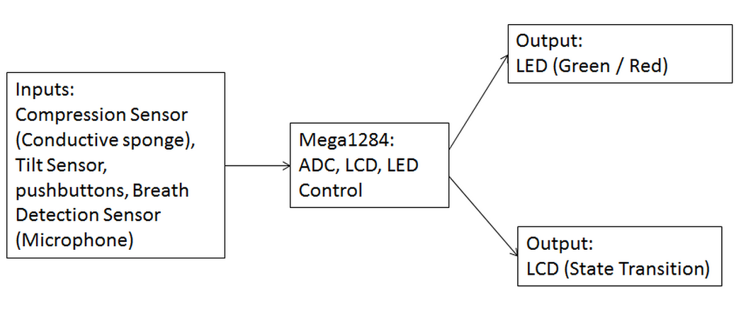
Figure 1: Overview of
System
The
CPR Training Dummy has 4 different inputs, separately from the Compression
sensor, Tilt sensor, Push buttons and Breath detection microphone. They will be
computed at the microcontroller end through ADC, LCD and LED control and then
the results and corresponding feedback/guiding messages will be displayed on
the LCD as state transitions and through the LED as indications of status of
the dummy.
Hardware/Software
Tradeoffs
We
chose to use the internal differential amplifier with gain for our microphone
detection circuit instead of building an external diff. amp with gain circuit
and reading the output. This added software complexity but reduced area and
cost. We chose to use compression sensors instead of force sensors to detect
the compressions since we could use a small amount of the compression sensor to
detect compressions which results in a lower cost than using force sensors, and
the compression sensors have a springlike quality
which simulates the feeling of compressing an actual chest. We used the microphone
to detect ventilations instead of our original idea of using a piezo sensor
because the piezo sensor was sensitive to any kind of vibrations such as stray
tapping of the manikin whereas the microphone only detected vibrations in the
speech range.
Standards
The
project complies with the ISO 9001 (quality management) and the International
Liaison Committee on Resuscitation (standardized CPR procedure) standards. The
manikin we chose is composed of nontoxic material and the plastic material used
was compliant with the ISO 9001 standards. The CPR process we followed in this
project is consistent with the standardized official CPR process from the
International Liaison Committee on Resuscitation guidelines.
Patents
Our
manikin may have a potential infringement issue with US patent 8,734,161 titled
CPR Training System using Consumer Electronic Device. Since we do not intend to
market our device for sale or otherwise profit from the device in any way, we
do not anticipate any issues with this patent. This patent does present an
issue if we were to pursue this project as a commercial venture. In terms of
software program, we borrowed codes from professor
Bruce Land under his permission, so we don’t foresee any patent or copyright
issue with this.
Software Design
LCD:
For
the LCD we have code that will display a string to the LCD and code that will
display an integer to the LCD. In order to get the string display to work, we
had to declare each string in program memory in advance.
Compression
detection:
For
compression detection we read the voltage from the compression sensor into the
ADC. When the ADC surpasses a threshold we register a compression. In order to prevent
multiple compressions from being registered from the same compression event we
“debounce” the compression sensing code by setting a debounce flag high when the ADC threshold is reached and
preventing other compressions from being registered until the debounce flag is cleared when the ADC goes back under the
threshold.
Nose
pinch detection:
Nose
pinch detection is done simply by reading the value of a push button switch
placed in the right nostril. If the button is pushed the nose is considered
pinched.
Tilt
detection:
Tilt
detection is done simply by reading the value of a tilt switch placed behind
the mask. If the sensor is tilted downwards by 30 degrees the neck is
considered tilted.
Ventilation
detection:
If
the nose is pinched and the neck is tilted, then ventilations are allowed to be
registered. A ventilation will only be registered if
the ADC reading the differential output of the microphone circuit exceeds the
threshold for 700 milliseconds, to simulate the fact that ventilations must be
given such that the chest rise of the patient is visible and this takes a lot
of air. The microphone circuit only responds to forceful exhalations.
Timer:
We
had a millisecond timer we implemented based on the millisecond timer used in
Bruce Land’s Cricket Call Generator. We had a counter which tracked timer
overflows on timer0 at full speed and after 62 counts we registered one
millisecond.
Our
main while loop is contained entirely in the state machine shown in figure 2:
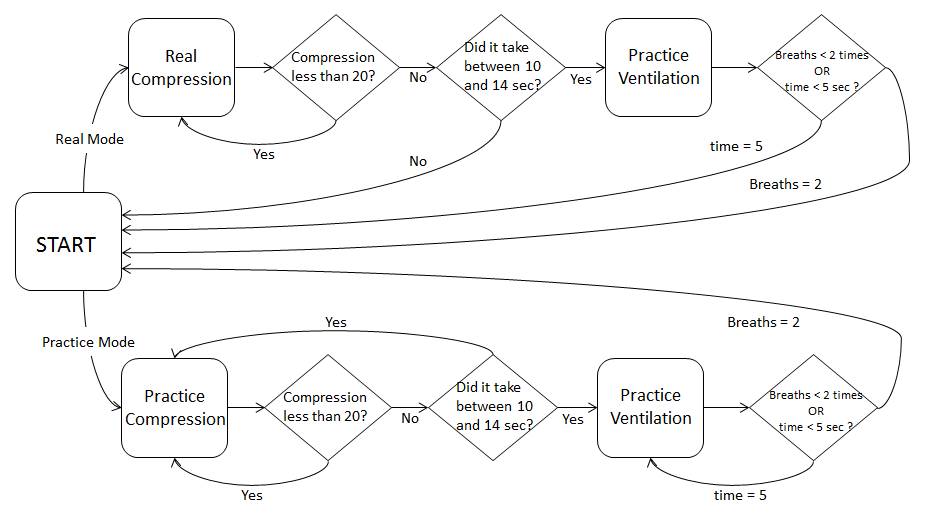
Figure 2: Finite
State Machine Diagram
There
are 5 states in our state machine:
Start
Menu:
The
start menu presents the user with the option to enter the real game mode or the
practice game mode. If they choose to enter the real game mode, the screen will
display a message informing them of their selection and then begin a countdown
to the game. If they choose to enter into practice mode the screen will display
a message informing them of their selection, give directions on how to perform
the compressions properly, and then begin a countdown to the game. The game
will always begin in compression mode, and the manikin’s eyes will turn red
when the game begins. A start flag is set to ensure that the start menu is not
entered into again until the practice game is won or the real game is over (win or lose).
Practice
Compression:
The
practice compression mode will check for 20 compressions. After 20 compressions
are given, there will be a check to determine if the compressions were given in
an acceptable time frame (10 - 14 seconds) according to the CPR recommended
rate (100 compressions/min) with an error tolerance of
±20 compressions/min. The number of compressions given and the elapsed
time are both displayed on the screen. After each compression the manikin’s
eyes flash green. If the compressions were given in the correct time window
then the game moves on to the practice ventilation state. Before entering the
practice ventilation state, the game will tell the user how to correctly
perform ventilations by reminding them to tilt the jaw and pinch the nose shut
before ventilating. If compressions are given incorrectly then the game reminds
the user how to perform compressions and then restarts the compression state.
Practice
Ventilations:
The
practice ventilation mode will check for 2 breaths in a window of 5 seconds.
The number of breaths and the elapsed time will be displayed on the screen.
During ventilations the manikin’s eyes will flash green. If the breaths are
given in time the game will display a win message, the manikin’s eyes will turn
green, and the game will go back to the start menu. If the breaths are not
given in time the game reminds the user how to perform ventilations and then
restarts the ventilation state.
Real
Compression:
The
real mode is meant to be a more challenging mode which does not provide any
feedback and puts the CPR skills learned in practice mode to the test. The real
compression mode will check for 20 compressions. After 20 compressions are
given, there will be a check to determine if the compressions were given in an
acceptable time frame (10 - 14 seconds) according to the CPR recommended rate (100 compressions/min) with an error tolerance of ±20
compressions/min. If
the compressions are given correctly then the game will display an encouraging
message and moves on to the real ventilation state. If
the compressions are given incorrectly then the game displays a lose message
and goes back to the start menu.
Real
Ventilation:
The
practice ventilation mode will check for 2 breaths in a window of 5 seconds. If
the breaths are given in time the game will display an encouraging message, go
back to compression mode, and increment a “success” counter which tracks
successful CPR cycles. If the breaths are not given in time the game returns to
the start menu. If x number of successes occur in succession, the game displays
a win message, the manikin’s eyes turn green, and the game returns to the start
menu. This number of successes is set to 1 in our code but can be changed
easily.
Hardware Design
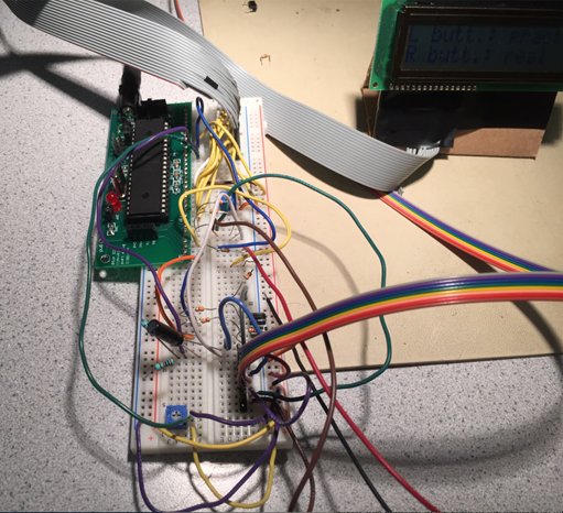
Figure 3:
Microcontroller board and circuits
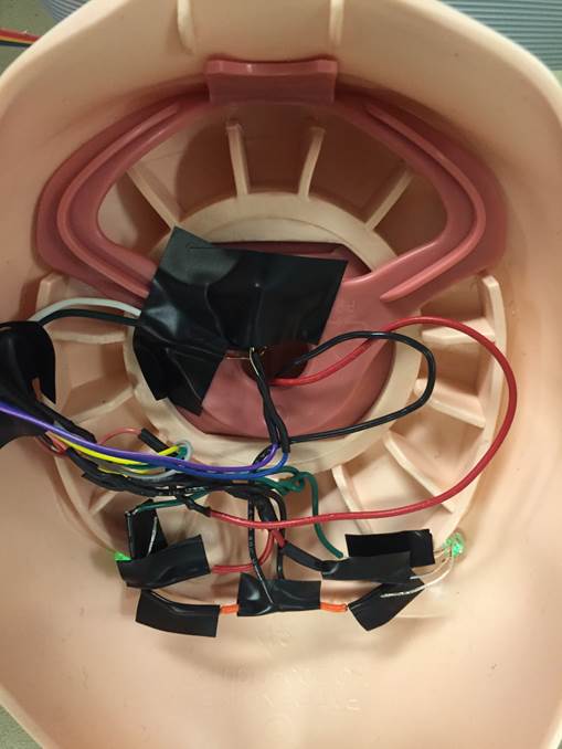
Figure 4: Circuit
hidden under the mask
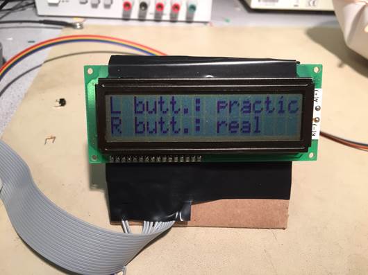
Figure 5: LCD
displaying mode selection message
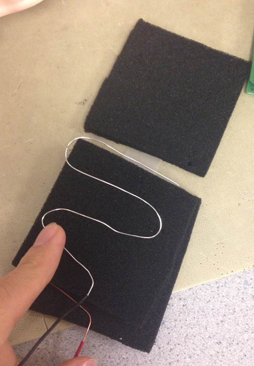
Figure 6: Compression
detection System
At
first we used a piezoelectric sensor to detect if ventilations were being
delivered but we found piezoelectric sensing was too sensitive to all
vibrations to our device, not just the vibrations caused by forceful breathing
unto the device. For this reason we switched to a microphone which was
sensitive to forceful breaths only, however the response of the microphone by
itself was on the order of millivolts as confirmed by oscilloscope. In order to
increase the sensitivity to useful levels we created the circuit shown in
Figure 7. This circuit decouples the AC response of the microphone from the DC
since we are just interested in the frequency response induced by a forceful
breath, and biased the inverting input and non-inverting inputs to Vcc/2. The amplifier used in the circuit was an internal
differential amplifier in the ATMega1284p with the gain set to 10. In order to
ensure the voltage at the inverting input matched the voltage at the
non-inverting input when the microphone was not being stimulated, we used 1%
tolerance resistors and tuned a trimpot to match the
inputs, and when it was being stimulated the AC response of the mic would be
read by the ADC.
To
detect chest compressions we firstly placed two wires into a 2-inch square of
conductive foam and compressed it in order to see the results. We found this
approach resulted in a sensitivity which was too low for our purposes. In order
to increase the sensitivity of our conductive foam to compression, we layered
two striped s-shaped wires between three 2-inch squares of conductive foam, as
shown in figure 6.
Port
A, on A.0, contained the ADC we used to detect compressions,
and the inverting and non-inverting inputs of the internal differential
amplifier with ADC on A.3 and A.2, respectively.
Port
C was connected to the LCD to control the messages displayed to the user during
operation. The LCD screen was attached to the chest of the manikin so the user
can see the messages conveniently while operating the device.
Port
D contained all of the digital control inputs, and the outputs to the LED
“eyes”. There were two push buttons used to select game mode (real vs.
practice) on D.0 and D.1, a tilt switch that detected neck tilt on D.3, a push
button used to detect nose pinching on D.4 and the RGB LED eyes were connected
to D.5 and D.6. We only needed red and green LEDs but not blue to indicate if
the dummy is still in the critical condition or back to life.
Also,
a resistor with a resistance of 330 ohms was placed before each input port to
make sure the circuit will not be shorted.
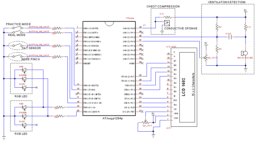
Figure 7: Hardware
Schematic for the whole system
Results of the Design
The
final prototype dummy has all functionalities we set out to have at the beginning.
The mechanical design made sure all wires and electrical components were well
organized and hidden under the plastic boards and mask of the dummy so they are
portable and hard to be damaged. The speed of execution is good for the overall
system as there is no hesitation, flicker or interactiveness
problems observed during our demo. We were able to accurately detect the
compressions and breaths by using debouncing
methodology in our software design. The finite state machine was designed and
implemented so that the potential interactiveness of
user action were taken care of and limited by different states. Real time
instructions for the user were displayed at the correct timing on the LCD. For
example, as soon as the user successfully finished the compression part in the
practice mode, the message reminding the user that the system now entered the
ventilation part and the instructions of the correct procedure of the
ventilation were displayed on the LCD. The most time consuming functions in our
code were the LCD display and the A/D conversion functions. We experienced some
difficulties when trying to dynamically update the LCD display while detecting
the user actions, such as a chest compression, due to the large amount of time
it took for each LCD display function to finish running. We got this problem
solved by moving the long strings of messages out of the loops in our code so
that they do not get run in each iteration. The
detected analog signals were transferred to the board and converted into digital
signals to be fed into the mcu almost
instantaneously, so we didn’t see any delay problem for this part either. At
the end, the system worked smoothly and guaranteed fairly comfortable user
experience.
In
terms of accuracy, the system behaved well. First of all, the timer code we
used in this lab was carried along from one of our previous labs, the Cricket
Call Generator, so we knew the timer worked with high accuracy. While the timer
worked as desired, there was a known 11.9 microsecond difference between the
counter milliseconds and an actual millisecond, which is about a 1.2% error
range and was acceptable since our project did not require super high accuracy
in terms of time keeping. The compression detection system was able to
precisely capture all compressions with good quality and compressions executed
on the wrong area or with not strong enough force on the dummy will not be
recorded as we designed. The tilt switch did a great job at controlling the mcu to not record any breaths from the user until the jaw
of the dummy is tilted upward by at least 30 degrees. The RGB leds blinked exactly once without any observed delay in
green whenever a good quality compression or breath is detected in the desired
time range. After careful tuning of the potentiometer resistance in the
differential amplifier circuit, the microphone circuit was capable of telling
the actual breaths apart from the random vibrations caused by user actions such
as tapping on the mask so that random vibrations wouldn’t be taken as breaths.
However, if the trimpot value was off by even just a
little bit, the sensitivity of the microphone to turbulent vibrations would
change a lot, and thus harming the accuracy of the ventilation detection
system. Our design also required the user to pinch the dummy’s nose before
he/she breaths into the airway and we placed a push button in the right nostril
to realize this. As the push button simply pulls the output high or low, we
never run into any accuracy trouble for this part. The accuracy of the hardware
also depended on the quality of the soldering and wiring. To ensure a high
soldering quality, we always had two people cooperate on the soldering work and
we used heat shrinks to hold the soldered wires in place. Overall, the system
ran with acceptable accuracy.
As
there are many long wires in our hardware part and the wires within the
compression detection system are exposed, our mechanical design had to make
sure all circuits are well covered under nonconductive material to avoid shorts
and shock risk. We hid the ventilation system circuit under the mask of the
dummy and held the circuit in place with electric tape and super glue. In the
similar way, the compression detection system was totally covered under a hard
thick plastic layer of the dummy. As plastic material is not conductive, we
completely insulated the internal circuitry from the user. Besides this, our Vcc power for the whole system is 5 volts, which is within
the human electricity tolerance range, if we consider the human body’s resistance
to be around 1000 ohms. The dummy we chose used nontoxic material and should be
not harmful to the health of the user. The dummy could be used for CPR training
in hospitals, schools, and at home. As all parts can be integrated into the
dummy and the dummy itself can be deflated, the whole system is highly
portable. The setup of the system is also very easy as the user only needs to
inflate the dummy and plug a 5 volt power supply into the microcontroller.
People who are able to perform the CPR process should be able to use this
system with ease.
Conclusions
The
results of our design met the initial goals we set. The system worked as we
initially designed and expected. However, we could have placed more conductive
sponges at different chest positions to detect forces at all areas to more
closely pinpoint the hand placement of the user to provide even more precise
feedback. The user interface could also be more friendly,
for example, we could write an Android application to wirelessly communicate
with the microcontroller and display all real time messages on the mobile
screens instead of the small LCD screen. In conclusion, we are happy with our
results and there is still much potential in our project and we will be able to
improve it if given more time.
In
compliance with the IEEE code of ethics, our device will be conducive to the
health and welfare of the public, and we are not aware of any issues which may
endanger the public. We stated the claims of our device honestly. We do not
have any potential conflicts of interest. We did not take any bribes. We
improved the application and consequences of technology by developing a device
which could potentially save many lives. We worked within our scope of experience
and limitations. We accepted all criticism and made all efforts to correct any
errors and credit the work of others. We treated all of our members fairly and
did not engage in discrimination based on the differing ages, national origins,
and sexual orientations of our lab members. We accepted honest criticism of our
work. We avoided harming others in any way. We assisted each other in our
professional development and in following the IEEE code of ethics.
There
was a potential issue with a U.S. patent for Real-time evaluation of CPR
performance but that patent describes a system that will evaluate the
performance of a practitioner during an actual emergency and not for a training
device. And since we didn’t plan to commercialize our project, we don’t foresee
any patent issue. We didn’t use any code in public domains. We borrowed codes
from professor Bruce Land under his permission.
Appendix A: Commented program listing
/* Final CPR training dummy test
code
Authors:
Rameez
Qurashi (rq35@cornell.edu)
Sungjoon
Park (sp2283@cornell.edu)
Haoyuan
Chen (hc576@cornell.edu) */
/* Port A:
A0 - Compression sensor
A2 - Microphone AC
input
A3 - Microphone
differential reference voltage
Port C:
C0-2, C4-7 - LCD
Port D:
D0 - Practice mode select
button
D1 - Real mode select button
D3 - Tilt sensor
D4 - Nose pinch detection
button */
#include <inttypes.h>
#include <avr/io.h>
#include <avr/interrupt.h>
#include <avr/pgmspace.h>
#include <stdio.h>
#include "lcd_lib.h"
#include <stdlib.h>
#include <string.h>
#include <util/delay.h> // needed for lcd_lib
// I like these definitions
#define begin {
#define end }
// game states
#define compstate
0
#define ventstate
1
//Strings used by game
const int8_t LCD_initialize[]
PROGMEM = "LCD Initialized\0";
const int8_t welcome[] PROGMEM = "Welcome
";
const int8_t select1[] PROGMEM = "L butt.:
practice";
const int8_t select2[] PROGMEM = "R butt.: real
";
const int8_t practicemode[]
PROGMEM = "practice mode ";
const int8_t realmode[] PROGMEM =
"real mode ";
const int8_t three[] PROGMEM = "3
";
const int8_t two[] PROGMEM = "2
";
const int8_t one[] PROGMEM = "1
";
const int8_t go[] PROGMEM = "GO!
";
const int8_t readyvent1[] PROGMEM = "get ready for
";
const int8_t readyvent2[] PROGMEM = "ventilation
";
const int8_t readycomp1[] PROGMEM = "get ready for
";
const int8_t readycomp2[] PROGMEM = "compressions
";
const int8_t losemessage1[] PROGMEM = "you suck
";
const int8_t losemessage2[] PROGMEM = "start over
";
const int8_t winmessage[] PROGMEM
= "nice job you win!";
const int8_t compdir1[] PROGMEM = "20 compressions
";
const int8_t compdir2[] PROGMEM = "at 100/min
";
const int8_t compdir3[] PROGMEM = "under the
";
const int8_t compdir4[] PROGMEM = "sternum
";
const int8_t ventdir1[] PROGMEM = "pinch nose shut
";
const int8_t ventdir2[] PROGMEM = "and tilt chin up
";
const int8_t ventdir3[] PROGMEM = "give 2 breaths
";
const int8_t ventdir4[] PROGMEM = "for 2 secs. each ";
const int8_t keepgoing[] PROGMEM
= "keep going! ";
const int8_t remindervent1[] PROGMEM = "tilt chin and
";
const int8_t remindervent2[] PROGMEM = "pinch nose
";
const int8_t timeremaining[]
PROGMEM = "time: ";
const int8_t breaths[] PROGMEM = "breaths:
";
const int8_t comps[] PROGMEM = "comps:
";
// Timer variables
// the volitile
is needed because the time is only set in the ISR
#define countMS
62 //ticks/mSec
volatile unsigned int time ;
int count;
//
used to count milliseconds
// raw A to D number
char Ain ;
// initialize variables used in main
int state = compstate;
int practice =
1; // 1 - practice
mode, 0 - real mode
int comp_time_high = 14000; //
low bound of compression detection window
int comp_time_low = 10000;
// high bound of compression detection window
int vent_time =
15000; //
ventilation detection window
int start =
0;
// 0 - (re)start, 1 - continue game
int num_comp =
0; // tracks
compressions
int breaths = 0;
// tracks breaths
int success =
0; // tracks
successive successes in real mode
int debounce =
0; // used to
"debounce" compressions and breaths
int vent_record_time;
int breath_time =
700; // length of
good ventilation
int successthreshold = 1;
/* how many successive compressions to win
only applies in real mode */
// thresholds
int basethreshold;
int compthreshold;
int ventthreshold=200;
int8_t lcd_buffer[17]; //
LCD display buffer
//**********************************************************
// LCD setup
void init_lcd(void)
begin
LCDinit(); //initialize
the display
LCDcursorOFF();
LCDclr(); //clear
the display
LCDGotoXY(0,0);
end
//*****************************************************
//1 sec counter
ISR (TIMER0_OVF_vect)
begin
//
generate time base for MAIN
//
62 counts is about 1 mSec
count--;
if (0 == count )
begin
count=countMS;
time++; //in Sec
end
end
//*****************************************************
//ADC read channel
int read_ADC(int ch_sel)
begin
//init
the A to D converter
//channel zero/ left adj /EXTERNAL Aref
//!!!CONNECT Aref jumper!!!!
if
(ch_sel < 8)
ADMUX
= (1<<ADLAR) | (1<<REFS0) + ch_sel;
else
return -1;
//enable ADC and set prescaler to 1/128*16MHz=125,000
//and clear interupt enable
//and start a
conversion
ADCSRA =
(1<<ADEN) | (1<<ADSC) + 7 ;
//get the sample
Ain = ADCH;
//start
another conversion
ADCSRA
|= (1<<ADSC) ;
return Ain;
end
//*****************************************************
// ADC read differential input
between A2 and A3 with gain of 10
int read_ADCdiff()
begin
//init
the A to D converter
//channel zero/ left adj /EXTERNAL Aref
//!!!CONNECT Aref jumper!!!!
//
0x0d enables differential x10 gain between A2 and A3...
//
... to read microphone input
ADMUX
= (1<<ADLAR) | (1<<REFS0) + 0x0d;
//enable ADC and set prescaler to 1/128*16MHz=125,000
//and clear interupt enable
//and start a
conversion
ADCSRA =
(1<<ADEN) | (1<<ADSC) + 7 ;
//get the sample
Ain = ADCH;
//start
another conversion
ADCSRA
|= (1<<ADSC) ;
return Ain;
end
//*****************************************************
// print int
to LCD
int LCDprintInt(int input, int line)
begin
sprintf(lcd_buffer,"%-i
",input);
LCDGotoXY(7,
line);
LCDstring(lcd_buffer, strlen(lcd_buffer));
end
//*****************************************************
// print "3, 2, 1, GO!"
sequence
void go321()
begin
LCDclr();
CopyStringtoLCD(three,
0, 0);
time
= 0;
while (time < 1000);
CopyStringtoLCD(two, 0, 0);
time
= 0;
while (time < 1000);
CopyStringtoLCD(one, 0, 0);
time
= 0;
while (time < 1000);
CopyStringtoLCD(go, 0, 0);
time
= 0;
while (time < 1000);
LCDclr();
end
//*******************************************************
void main(void)
begin
init_lcd();
//on board led for
testing
DDRD = 0x50; // LED
"eyes" on d5 and d6 outputs
PORTD = 0x1f; // d.0-1,3,4 pull ups high, LED "eyes" off
// timer 0 runs at
full rate
TCCR0B = 1 ;
//turn on timer 0 overflow ISR
TIMSK0 =
(1<<TOIE0) ;
// turn on all ISRs
sei() ;
time = 0;
// game loop
while
(1)
begin
if
(start == 0)
begin
CopyStringtoLCD(welcome,
0, 0);
time=0;
while (time < 3);
// display select message to user
CopyStringtoLCD(select1,
0, 0);
CopyStringtoLCD(select2,
0, 1);
// wait for user to select mode
while (1)
begin
//
if left switch is pressed go into practice mode
if
(~PIND & 0x01)
begin
practice = 1;
LCDclr();
CopyStringtoLCD(practicemode, 0, 0);
PORTD
= 0x3f; // d.0-1,3,4 pull ups high, LEDs red
time = 0;
while (time < 3000);
// prepare
user to deliver compressions
CopyStringtoLCD(readycomp1,
0, 0);
CopyStringtoLCD(readycomp2,
0, 1);
time = 0;
while (time < 3000);
//
give directions to deliver compressions
CopyStringtoLCD(compdir1,
0, 0);
CopyStringtoLCD(compdir2,
0, 1);
time = 0;
while (time < 3000);
CopyStringtoLCD(compdir3,
0, 0);
CopyStringtoLCD(compdir4,
0, 1);
break;
end
//
if right switch is pressed go into real mode
else
if (~PIND & 0x02)
begin
practice = 0;
LCDclr();
CopyStringtoLCD(realmode, 0, 0);
PORTD
= 0x3f; // d.0-1,3,4 pull ups high, LEDs red
break;
end
end // end game mode selection if
time = 0;
while (time < 2000);
go321();
start = 1;
end
// end (re)start sequence
// practice mode state
machine
if
(practice == 1)
begin
switch (state)
begin
case compstate: // compression
state in practice mode
/*
progression occurs if 20 compressions are given
within 10-14 seconds */
//
compression pad is on A0
debounce = 1;
compthreshold = 10;
time = 0;
CopyStringtoLCD(comps,
0, 0);
CopyStringtoLCD(timeremaining, 0, 1);
//
detect and debounce compressions
while
(num_comp < 20)
begin
if ((debounce == 0) && (read_ADC(0)
< compthreshold))
begin
num_comp++;
debounce = 1;
PORTD = 0x5f; // d.0-1,3,4 pull ups high, LEDs green
end
if (read_ADC(0) > (compthreshold))
begin
debounce = 0;
PORTD = 0x3f; // d.0-1,3,4 pull ups high, LEDs red
end
LCDprintInt(num_comp, 0);
LCDprintInt(time,
1);
end
PORTD
= 0x3f; // d.0-1,3,4 pull ups high, LEDs red
//
if compressions are done within the proper time window
//
move to ventilation state
if ((time <= comp_time_high)
&& (time >= comp_time_low))
begin
state = ventstate;
num_comp = 0;
time = 0;
//
prepare user to give ventilations
CopyStringtoLCD(readyvent1,
0, 0);
CopyStringtoLCD(readyvent2,
0, 1);
time = 0;
while (time < 3000);
//
give user directions on ventilation
CopyStringtoLCD(ventdir1,
0, 0);
CopyStringtoLCD(ventdir2,
0, 1);
time = 0;
while (time < 3000);
CopyStringtoLCD(ventdir3,
0, 0);
CopyStringtoLCD(ventdir4,
0, 1);
time = 0;
while (time < 3000);
go321();
end
//
if compressions are done too quickly or slowly
//
print failure message and go back to compressions
else
begin
state = compstate;
num_comp = 0;
time = 0;
//
print lose message
CopyStringtoLCD(losemessage1,
0, 0);
CopyStringtoLCD(losemessage2,
0, 1);
time
= 0;
while
(time < 3000);
// prepare user to
deliver compressions
CopyStringtoLCD(readycomp1,
0, 0);
CopyStringtoLCD(readycomp2,
0, 1);
time
= 0;
while
(time < 3000);
// give directions to
deliver compressions
CopyStringtoLCD(compdir1, 0,
0);
CopyStringtoLCD(compdir2, 0,
1);
time = 0;
while (time < 3000);
CopyStringtoLCD(compdir3,
0, 0);
CopyStringtoLCD(compdir4,
0, 1);
time = 0;
while
(time < 3000);
go321();
end
break; // end compression state
case ventstate: // ventilation
state in practice mode
//
check for 2 ventilations for 5 seconds
//
piezo vibrator is on A1
time = 0;
debounce = 0;
CopyStringtoLCD(comps,
0, 0);
CopyStringtoLCD(timeremaining, 0, 1);
//
detect and debounce ventilations
while ((time < vent_time)
&& (breaths < 2))
begin
//
remind user to tilt chin and pinch nose if they aren't
if (PIND != 0x07)
begin
LCDclr();
CopyStringtoLCD(remindervent1, 0, 0);
CopyStringtoLCD(remindervent2, 0, 1);
LCDclr();
end
//
only register breaths if chin tilted and nose pinched
else if ((debounce == 0)
&& (read_ADCdiff() > ventthreshold))
begin
breaths++;
debounce = 1;
vent_record_time = time;
PORTD = 0x5f; // d.0-1,3,4 pull ups high, LEDs green
end
//
only register breath if it is given for long enough
if (time > vent_record_time + breath_time)
begin
debounce = 0;
PORTD = 0x3f; // d.0-1,3,4 pull ups high, LEDs red
end
LCDprintInt(breaths,
0);
LCDprintInt(time,
1);
end
PORTD = 0x3f; // d.0-1,3,4 pull ups high, LEDs red
//
if breaths are given
//
display win message and set restart variable
//
to go back to main screen
if (breaths >= 2)
begin
state
= compstate;
num_comp
= 0;
time
= 0;
breaths = 0;
// reset start flag
start
= 0;
//
display win message
LCDclr();
CopyStringtoLCD(winmessage, 0, 1);
PORTD
= 0x5f; // d.0-1,3,4 pull ups high, LEDs green
time = 0;
while
(time < 3000);
end
//
if not enough breaths given in time
//
display lose message and go back to ventilations
else if (breaths < 2)
begin
state
= ventstate;
breaths
= 0;
time
= 0;
// print lose message
CopyStringtoLCD(losemessage1,
0, 0);
CopyStringtoLCD(losemessage2,
0, 1);
time = 0;
while
(time < 3000);
// prepare user to give
ventilations
CopyStringtoLCD(readyvent1,
0, 0);
CopyStringtoLCD(readyvent2,
0, 1);
time = 0;
while
(time < 3000);
//
give user directions on ventilation
CopyStringtoLCD(ventdir1, 0,
0);
CopyStringtoLCD(ventdir2,
0, 1);
time = 0;
while
(time < 3000);
CopyStringtoLCD(ventdir3,
0, 0);
CopyStringtoLCD(ventdir4,
0, 1);
time = 0;
while
(time < 3000);
go321();
end
break; // end ventilation state
end // end switch
end
// end practice if
// real mode state
machine
if
(practice == 0)
begin
CopyStringtoLCD(keepgoing, 0, 0);
switch
(state)
begin
case compstate: // compression
state in real mode
//
check for 20 compressions within time window (10-14 seconds)
//
compression pad is on A0
basethreshold = read_ADC(0);
compthreshold = 10;
time = 0;
//
check for and debounce compressions
while
(num_comp < 20)
begin
if ((debounce == 0) && (read_ADC(0) < compthreshold))
begin
num_comp++;
debounce = 1;
end
if (read_ADC(0) > (compthreshold))
debounce = 0;
end
//
if compressions are done within time window
//
move to ventilation state
if ((time < comp_time_high)
&& (time > comp_time_low))
begin
state = ventstate;
num_comp = 0;
time = 0;
end
//
if compressions are done too quickly or too slowly
//
print failure message and go back to compressions
else
begin
state = compstate;
num_comp = 0;
time = 0;
//
print lose message
CopyStringtoLCD(losemessage1,
0, 0);
CopyStringtoLCD(losemessage2,
0, 1);
//
set restart variable and clear successes
start = 0;
success = 0;
time
= 0;
while
(time < 3000);
end
break; // end compression state
case ventstate: // ventilation
state in practice mode
//
check ventilations for 5 seconds
//
piezo vibrator is on A1
time = 0;
while ((time < vent_time)
&& (breaths < 2))
begin
//
only register breaths if head is tilted and nose is pinched
if ((debounce == 0) && (read_ADCdiff()
> ventthreshold) && (PIND == 0x07))
begin
breaths++;
debounce = 1;
vent_record_time = time;
end
//
make sure breaths are given for long enough
if (time > vent_record_time + breath_time)
debounce = 0;
end
//
if breaths are given and enough consecutive successes are had
//
display win message and set restart variable
//
to go back to main screen
if
(breaths >= 2)
begin
state = compstate;
num_comp = 0;
time = 0;
breaths = 0;
//
display win message when there are 5 consecutive good cycles
if (success == successthreshold)
begin
LCDclr();
CopyStringtoLCD(winmessage, 0, 1);
PORTD
= 0x5f; // d.0-1,3,4 pull ups high, LEDs green
start = 0;
end
else success++;
time = 0;
while (time < 3000);
end
//
if not enough breaths given in time
//
display lose message and go back to ventilations
else if (breaths < 2)
begin
state = ventstate;
breaths = 0;
time = 0;
//
print lose message
CopyStringtoLCD(losemessage1,
0, 0);
CopyStringtoLCD(losemessage2,
0, 1);
//
set restart variable and clear successes
start = 0;
success
= 0;
time = 0;
while
(time < 3000);
end
break; // end vent state
end // end switch
end
// end real if
end
// end while loop
end // end
main
Appendix B: Budget
Mega1284
x
1 $5.00
STK500
x
1 $15.00
Power
Supply x 1
$5.00
Custom
PCB x
1 $4.00
White
Board x
1 $6.00
Tilt
Switch x
1 $1.95
Push
Switch x 3
$1.50
Conductive
Sponge x 3 $0.36
RGB
LED x2
$2.02
CPR
training Manikin x 1 $34.95
LCD
(16x2) x
1 $8.00
Microphone
x
1 $1.40
---------------------------------------------
Total
= $85.18
Appendix C: Tasks carried out by each team member
·
Wiring for the hardware
circuits and soldering for the LED display: Haoyuan
Chen
·
Designing and
Implementing the state machine in software: Sungjoon
Park and Rameez Qurashi
·
Whole circuit design and
integration: Shared
·
Researching about
electrical components: Shared
·
Microcontroller code
implementation and debugging: Shared
·
Website Content and
Formatting: Shared
References
Data
Sheets
Vendor
Sites
Code/designs
Borrowed from Others
Background
Sites
Prototype
Board for Atmel Mega1284