Matt Kagie, Mashrur Mohiuddin
Real-Time Pitch Shifter.
Introduction
"A device that pitch-shifts voice in real time"
For our final project, we attempted to implemented a real-time vocal pitch shifter. The system was designed to work as follows: a user speaks into a microphone, their vocals are processed using a pitch shifting algorithm, and the resulting signal is output through speakers. All of this is done within a time interval such that the user does not reasonably notice the delay between their spoken voice and the pitched voice. To set the shifting level, the user must press one of two buttons, representing a shift of an octave down or up.
The motivation behind this project was to create a system that could be used in a live musical environment. An artist could utilize the pitch shifter to harmonize their vocals perfectly while performing, without the need of any backup singers. The artist could also shift their voice to inhumanly pitches, making for interesting effects. Additionally, this product could also be used for recreational purposes, for anyone who wishes to experiment with their music.
High Level Design
Rationale
The original idea behind this project was to create a live auto-tune machine. This unit would correct the pitch of input vocals to a specified key. However, it was discovered that the MCU did not have the computational capabilities required to accomplish such a task. Because of this, we decided to scale down our project to something a little more doable, and so we came up with the idea of pitch shifting. This, however, proved to be a little much for the MCU as well.
Mathematics
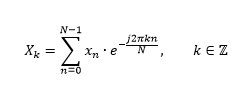
The math behind this project was centered around the fast Fourier transform (FFT) and its inverse transform (IFFT). An FFT is simply a fast and efficient implementation of the discrete Fourier transform (DFT), which converts a signal from the time domain to the frequency domain. The formula for the DFT is given as follows:
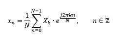
The DFT simply translates a set of samples into a list of coefficients corresponding to the samples' frequency contents. To convert back into the time domain, the inverse DFT is applied:
The DFT is a very powerful tool in digital signal processing; however it is very computation heavy. Computing it directly requires N2 complex multiplications and N(N-1) complex additions. FFTs reduce complexity by reducing the number of computations made. The most popular FFT is the Cooley-Tukey algorithm. This process takes a composite length N=N1N2 signal, performs an length N1 point DFT N2 times, and then an N2 point DFT N1 times, and repeats the process for the N1 and N2 length signals. The radix of the algorithm refers to the "split" of the input composite signal. For radix-2 (meaning the input is split twice, and those signals are split twice, and so on), this algorithm lowers the number of complex multiplications to (N/2)log2N complex multiplications and Nlog2N complex additions, effectively improving the complexity from O(N2) to O(NlogN). Because we are limited to an 8-bit microcontroller, these savings are crucial to a real time implementation. The FFT is defined to be in real time if it can run faster than the sampling time of the microphone, so the user does not have any noticeable delay between spoken voice and processed output sound.
To pitch shift with the FFT, one has to shift the frequency content of the signal in the desired direction. This may sound like a trivial task but it is actually rather complicated. Because the heart of the project involves frequency manipulation, it is only natural that the implementation should involve FFTs. As will be described later, this is what ended up proving to be too difficult to implement on the MCU.
Structure
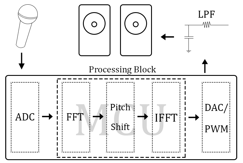
The flow of this project begins with a user speaking/singing into a microphone. This mic signal is fed into the ADC of the microcontroller to obtain a digital signal for manipulation. This signal is then FFT'd to get its frequency content, pitch shifted, and IFFT'd to return to the time domain. Once this is done, the result is output to the PWM, which is low-passed and fed to the speakers. The low-pass filter smooths out the PWM signal, reducing the clipping nature of square pulses.
Due to the FFT/IFFT, as well as the pitch shifting algorithm, this project is very computationally expensive. Because of this, it is advantageous to implement as much of the project as possible in hardware. Thus, signal boosting and all filters were done in hardware.
Standards
No wireless communications were used so no FCC rules were violated. Additionally, as long as no code of ethics was broken, no IEEE, ISO, etc. standards applied. While testing this project, extra caution was taken in order to avoid disturbing other groups in lab.
Program/Hardware Design
Hardware
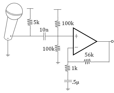
In hardware, there were two main subsystems: the microphone and the speaker. The mic was a small condenser mic obtained from the lab. It was fed into a filter that cut out frequencies outside the human vocal range. The first resistor and capacitor of the circuit acted as a low pass filter, whereas the resistive and capacitive feedback of the amplifier acted as the high pass filter. The mic also had a voltage shifter and amplifier. The filtered input signal from the mic was scaled/shifted accordingly so it would remain at about half of Vcc on average (or during silence), and it would have a range from 0 to Vcc. This way, a PWM cycle of 128 would correspond to no sound.
The speaker simply took in a low passed version of the microcontroller's PWM output.
Design of the hardware was relatively straightforward. A circuit was discussed in class that accomplished all that we needed to do. This circuit contained a filtering system, a voltage shifter, and an amplifier. The filter's resistor and capacitor components were chosen to filter the mic's output between 300 and 3000 Hz. This is just within the average human's vocals range. The resistors on the voltage shifter were chosen so that the voltage on the node between them was about half of Vcc, or 2.5 in this case. The amplifier was designed to have a gain of anywhere between 30 and 50.
There were two main issues that we ran into with hardware. The first was simply careless mistakes in calculation. At the start of the project, we had accidentally miscalculated our time constants for our filters. This resulted in a very choppy signal that was being output from the filter microphone. Upon examination of our circuit, we discovered that we were cutting out much of the low end of the frequency spectrum. RC values were recalculated to correct the problem, and the new circuit output a relatively clean signal after amplification.
The other hardware problem we encountered dealt with outputting sound from the MCU. Initially, we had been using the speakers provided in the lab to output the low-passed PWM signal. This had worked fine, but we decided to use headphones for testing to avoid disturbing others in lab. However upon doing so, sound had stopped being output. Using the oscilloscope, it was determined that the PWM was still present when not connected to headphones, but upon connecting them, the signal was killed. After talking to Professor Land, we discovered that the impedance of our headphones was too low. The impedance of the headphones was on the order of Ohms, while that of the lab speakers was on the order of tens of Ohms. This was causing loading issues. Once this was figured out, we decided to stick to testing with the speakers.
The main method of testing the hardware was via the oscilloscope, the function generator, and the speakers. The function generator was set to a frequency inside of our desired range. This was input through our circuit, and the output (that should go to the ADC) was measured on the oscilloscope. This was utilized until both the amplitude and cutoff frequencies desired were obtained. From there, the microphone and the speakers were connected to verify. Finally, the output of the circuit was input to the ADC, and the software began being tested.
Software
The large majority of the project was implemented in software. There 3 main software components: writing from the ADC, doing computation on the input data, and outputting the processed signal to the PWM.
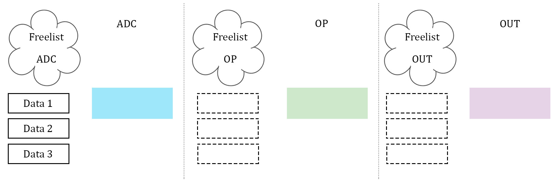
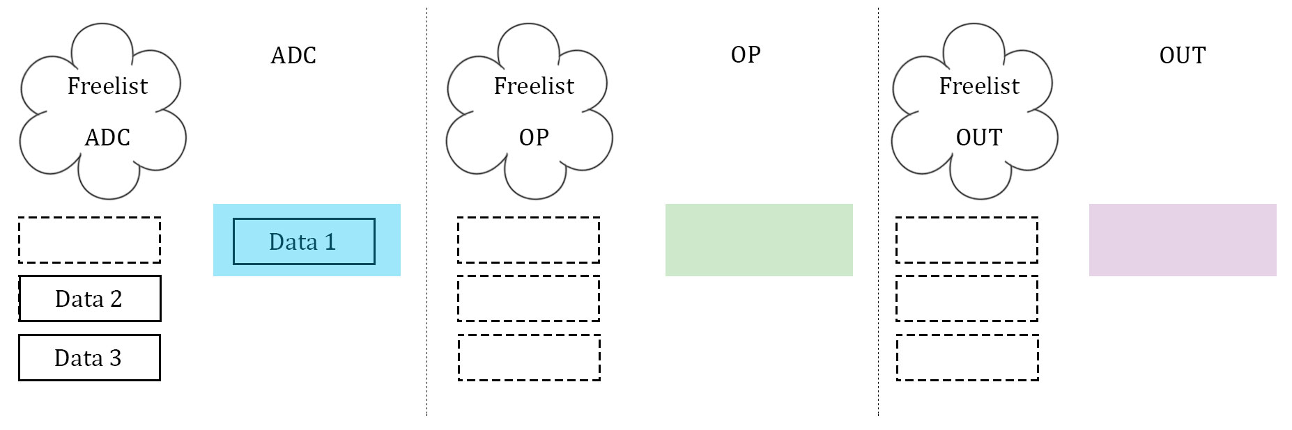
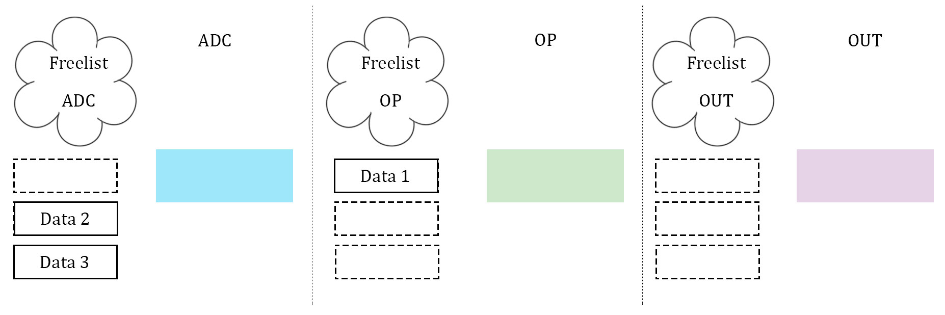
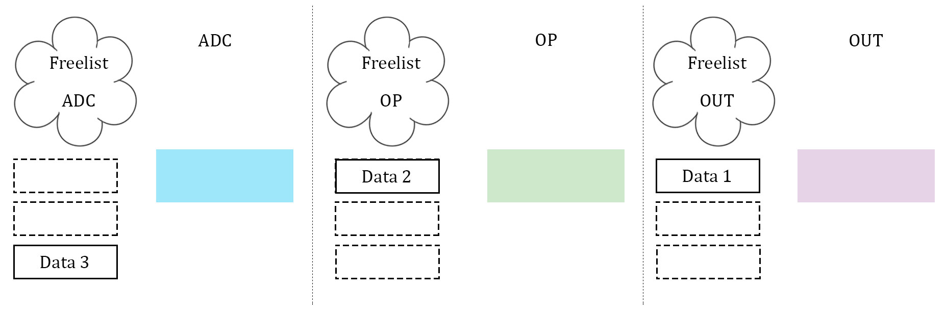
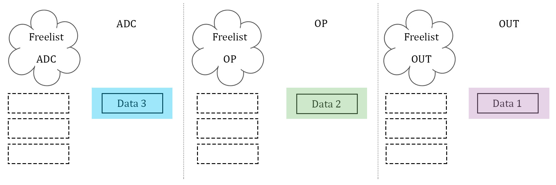
What proved to be the most difficult, as well as the most important, part of the software was getting the data to be manipulated on correctly. After several failed attempts, which will be described below, a scalable implementation of data management was created. This scheme was heavily biased by a computer architecture background. The three stages described above, namely ADC, data manipulation, and data output, were idealized. Three arrays to store data are used, and they are considered almost "packets" between the three stages. Each array has its own index to stop the issue of overwriting each other's index, and each stage has it's own flag to indicate which array it should be operating on. In addition, each stage has what is called a "free list". Much like register renaming in computer architecture, the free list is an array with one slot allocated to each array that the stage can operate on. If the array's corresponding slot is high, then the array is not being used by any other stage, and it is safe to operate on. If it is low (0), then that array is off limits to the stage. The diagrams illustrate our idea with 3 data units.
1:
2:
3:
4:

5:
6:
7:
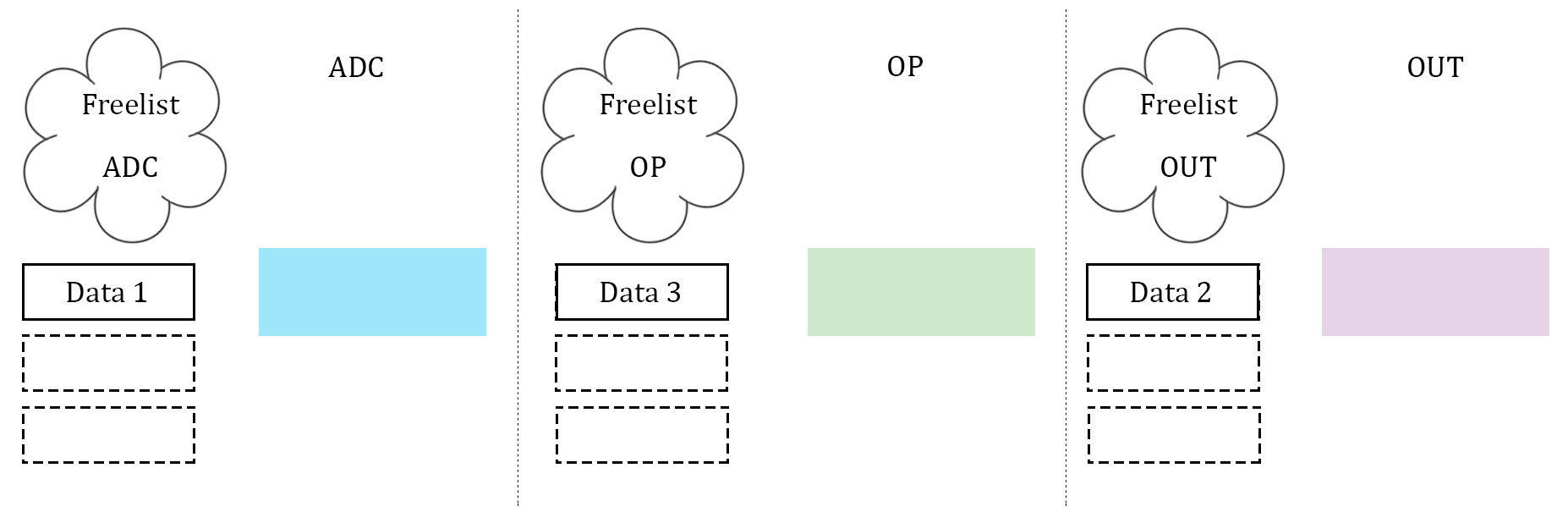
In essence, the free list acts as a buffer between each stage where the array can maintain if it has been completed by one stage and is waiting to be accepted by the next. Think of it as a register file in a communication channel. At the beginning of each stage, the stage checks its flag. The flag indicates which array should be operated on. From there, the stage checks its personal free list, and looks for the slot that represents the state of the array in question. If the array is able to be operated on, the stage operates on it. If it is not, the stage waits. Once a stage is finished operating on an array, it resets the array's personal index (so that the next stage can assume it starts at 0), it takes the array off of it's own free list (meaning that it is no longer ready to be manipulated on by that stage), and it notifies the next stage in the pipeline by setting the next stage's free list high (at least the slot that indicates the array in question). Finally, the stage's flag is incremented to point to the next array that is desired. This is how we kept data in order, as well as how we kept data from being overwritten. Since the middle stage (the data manipulation) acted as somewhat of a bottleneck (took longer than the other two stages), this manner allowed the first and third stage to continue at the same speed, and the extra buffers would simply wait in the channels. Best of all, this method was scalable to more arrays, and indeed we did increase to four arrays at one point to test the increase computation ability.
The following paragraphs will give you a general overview of the each individual function of our code:
TIMER0_OVR_vect ISR
The TIMER0 overflow ISR is responsible for reading in the ADC and outputting the ready data to the PWM to generate sound. Using the data management system described above in order to determine which array to write to and read from, the ISR was kept as simple and computationally inexpensive as possible. Every 8th iteration of the ISR (to keep the sampling frequency correct at 7.8kHz), the ADC would be read into a variable, and the ADC would be instructed to start another conversion. From there, the ISR would determine which array (if any) the value should be written into, and the value would be stored. If this array was filled, the ISR would indicate completion of that array in the manner consistent with the implemented data management system. From here, the ISR would check to see if any data is ready to be output to the PWM, and if it is, it would be output, and the output array would be incremented and possibly expelled to the adc's free list.
TIMER0 was set to run at 16MHz, meaning that the ISR executes at a rate of 62.5KHz (256 cycles to overflow). An accumulator was kept to only execute the code every eighth cycle, allowing for the system to operate at 7.8KHz, more than two times the highest frequency content of the input signal (and output signal).
MAIN
The main starts out with all of the initializations for the project. It begins by initializing the LCD. Although this was not a major part of our project, this was used multiple times in the debugging process. From here, TIMER0 is set up. The TIMER0 overflow interrupt ISR is enabled and the timer is set to run at full speed (16MHz). Next, the PWM wave is enabled to operate in fast PWM mode on output pin B3, and the OCR0A is set to initialize to 128 (meaning that silence is output from the speakers to begin with). Finally, the ADC is enabled and set to work off of port A0. It is set to compare to the internal 5V reference. The UART is also enabled, although this was used purely for debugging the IFFT function, as will be described later. Lastly, before the while loop, all of the variables are initialized, including indices, free lists, and the sinewave table used in the FFT code.
The while loop also operates on the data management system described above in order to not corrupt data. The main loop is in charge of the data manipulation stage of the pipeline. If the expected array is ready to be operated on, the main loop first takes the FFT of the data, then runs the pitch shifting function over the data, and finally takes the IFFT of said data. When this is complete, the main function passes the data to the next stage and looks to pull in the next set of data.
FFTfix
This function is in charge of executing the functionality described above in the Mathematics section of the report. The FFTfix function was taken from Professor Land's DSP page of his website. It is a fast Fourier transform algorithm that has been optimized for the microcontroller. This outputs two 128-point arrays, one for real components of the frequency, and one for phase. The arrays are redundant across the middle index.
IFFTfix
This function is a modified version of the FFTfix code described above. The only difference between a FFT and an IFFT is that, in the computations, the complex conjugate of the twiddle factors are used. This was reflected in the IFFTfix function.
Pitch shift
Multiple methods were attempted in order to achieve pitch shifting, and this is what was determined to be just too difficult for the microcontroller to handle. Three different methods were attempted. Demo code for implementing a pitch shift was found online from DSPDimension, and modified for the microcontroller. The code essentially does the following. An input buffer of sound data is windowed (multiplied by a periodic signal of the length of the FFT to be taken) in order to prepare for the FFT. From there, the FFT is taken, and the real and imaginary parts are converted to magnitude and phase. In the algorithm found online, some phase manipulation was also done. From there, the magnitude and phase are either spread or shrunk across the frequencies proportional to the pitch shift desired (shifting the pitch up corresponds to spreading the frequencies). Finally, the magnitude and phase are converted to real and imaginary again, the IFFT is implemented, and the output buffers are accumulated to allow smooth interpolation between the quantized FFT buffers. This is the Phase Vocoder method.
This method was attempted on the hardware, but was much too computationally heavy. The conversion from rectangular to polar and back to rectangular coordinates could not be optimized well enough (this required sines and cosines and arctangents of floating-point inputs, something that we could not figure out how to use a lookup table for, and something much too slow to be a part of a real-time algorithm). Therefore, many "hacks" and optimizations were attempted.
The basic idea above is to either shrink the frequency content across the spectrum into the lower half of the FFT array, or to spread it. We chose to first implement a shift-down algorithm, which would shrink the spectrum into the first part of the array. Therefore, the next iteration of the algorithm was to increment through both the real and imaginary arrays through the first quarter and assign them values of twice their index. What this does is shrink the frequency content of the first half of the array into the first quarter. From there, the second quarter of the arrays were set to 0 (thus zeroing out the higher frequencies, or so we thought). The first half of the arrays were then mirrored into the second half of the arrays (to simulate the symmetry in an FFT). However, the output of the IFFT indicated this was not correct.
Many iterations of the above code were implemented. Rather than shifting both the real and the imaginary components, we tried computing the magnitude of the frequency bins, shifting those into the real components, and setting the imaginary components equal to zero throughout the transform. The rationale behind this was that humans are fairly phase insensitive. When converting from magnitude and phase to real and imaginary in the demo code, the magnitude was multiplied by the cosine of phase for real values and the sine of phase for imaginary values. If phase is thrown away, then the reals would be multiplied by one, and the imaginary would be multiplied by zero. However, this did not solve our issue.
After playing around with this with all sorts of weird combinations of magnitude and phase, a totally different method of pitch-shifting was attempted. This one was handled in the time domain. The input data to the data manipulation part of our pipeline downsampled the signal. We focused on only pitch-shifting up by a factor of two. Thus, every other sample of the data was thrown out, and the input data was converted to length-64 array. This array was then output to the PWM at the same frequency. It kind of worked! Normally, when you downsample a signal and then play it at the same frequency, the pitch is shifted up, but the signal appears to being played at twice the speed. However, due to the very small nature of the arrays being operated on, the speed change went unnoticed, although a severe metallic nature was added to the output sound.
Due to the read/write nature of the program, a triple-buffered system was used.
The first stage is the write-input stage. A 128 point buffer is filled with ADC values at round 7800 samples/sec. Once this buffer is full, a flag is set to indicate that it is ready for processing.
The buffer then moves to the second stage, where it is pitch shifted. The signal is first converted to the frequency domain through a fixed-point FFT. Because we are using an 8-bit microcontroller, our FFT is limited to 128 points. The FFT is computed in place, meaning that the output is located in the same array as the input. Since the input to the FFT is always real as the signal is just a range of values from the ADC, the FFT we use is modified to be optimized to handle real only inputs. It outputs a real and imaginary array, from which phase and magnitude can be extrapolated.
Aside from the mathematical struggle indicated above for the pitch shifting algorithm, another real struggle for us was to operate on the data in a manner such that data would not be overwritten. This lead to our development of the above data management system, but we went through many iterations before this was achieved.
First, we tried simply outputting the ADC to the OCR0A right after being read in, to verify the ADC was reading in valid data. From there, we attempted only a single array of data. We would read in from the ADC, do nothing in data manipulation, and then write to the OCR0A. This worked. However, if you tried to do any data manipulation, a periodic noise signal would be generated, indicating corrupted data. We tried to implement a toggle flag. If toggle was high, read in the ADC, else output the ADC. However, we realized this would not allow any time to operate on the data. We altered to a double-array system with a toggle flag. If the toggle is high, read into array 1, output array 2. Vice versa for if toggle is low. However, again, this did not leave time to operate on the data. Thus, we tried to synchronize the switching between the two arrays with two flag, indicating when reading each array was done, and when operating on each array was done. We would base each stages start off of the previous stage's completion flag being raised. However, this did not work. We decided that more buffers were required. We scaled up to 5 arrays in total, and we ran the system off of three state flags, one for each stage. The state of the stage was to indicate which buffer that stage was supposed to be operating on (i.e. if state_adc = 1, array 1 would be in the ADC stage being operated on). We assumed that with this many buffers, data would not be overwritten. When an array was completed in a stage, the stage would increment its state flag to the next array. This worked very well for simply reading and outputting data. However, as soon as the FFT and IFFT were implemented, the output was not coherent. We realized that the stages were not being synchronized, and thus if one stage ran faster than the others, it would begin reading data that was not yet valid. We maintained the belief that 5 arrays was enough to solve this issue, so we tried to implement start flags. In other words, a flag would be raised after the very first array was full out of the ADC and passed to the data manipulation stage, and another flag was raised after this array was passed to the Output stage. These flags acted as ways to stagger the starting stages of the arrays so that there was some leeway in between each stage to try to avoid data corruption. This seemed to work perfectly, both for straight input and output, as well as FFT and IFFT data manipulation. It took us a while to realize that the flags were never raising high in data manipulation, meaning that the FFT and IFFT were never occurring, and no other form of data manipulation could be achieved. This was determined by observing the blinking of an LED. We decided to start following the ideas instilled in us by Computer Architecture. We simplified back to 3 buffers and went to implement a val/ready interface. A val/ready interface is designed to be latency insensitive, meaning that the data would not be overwritten. Each stage would have a valid and a ready flag. Valid indicated that the output of the stage is finished, and ready indicates that the stage is empty and looking for data to operate on. Data is passed between stages when the first stage's valid flag is high, and the second stage's ready flag is high. The valid and ready flags of each stage should never be high at the same time, as this would indicate that the stage has both valid data, and is empty, which does not make sense. However, upon thinking about this, the circular dependency of the three stages makes this implementation infeasible, as every stage must have both their valid and ready flags high to pass data around. This caused a deadlock once implemented, so no output could be achieved. Finally, the data management system described above was born.
Results
As stated before, this project was too computationally heavy to be fully implemented on an 8-bit CPU. The lack of computing power imposed very strict timing requirements. As one of our debugging techniques, we would blink the on-board LED at the start of our infinite while loop in main. If the system was running as fast as it should have (on the order of milliseconds), then the blink would not be distinguishable. This was true for all tasks up until we started signal manipulation. When the microphone signal was read in, FFT/IFFT'd, and output to the speakers, there was no perceivable blink on the LED. There was only a slight delay between the spoken and digital vocals, but more often than not it was not noticeable. However, trying to do some kind of pitch manipulation with the FFT would usually run the timing.
Unfortunately, our original idea of using the FFT to manipulate pitch never realized itself. The phase vocoder algorithm relied on the FFT to shift pitch. However as the name implies, this algorithm relies heavily on the phase of the signal to produce nice results. As the microcontroller cannot efficiently compute an arctangent, this severely degraded our performance, to the point where the input and output signals sounded nothing alike. Towards the early iterations of our implementation of the phase vocoder method, a normal input from the microphone would yield a very heavy, distorted, periodic signal. While we never truly discovered exactly what caused this error, we speculated that it was due to timing errors. The LED would blink much slower than it should have, indicating that our main while loop was not running up to speed. This most likely caused data overwriting, which is what gave us such a weird output.
Once we realized that a full phase vocoder algorithm was not feasible on this architecture, we decided to modify it and only take into account the magnitude of the FFT. We justified this decision because humans are largely phase insensitive, so the resulting time domain signal after processing would sound good enough for our purposes. However this also did not work. Although the loud and obnoxious periodic distorted signal previously encountered was no longer present, this iteration of our pitch shifting algorithm did not yield usable results. Now, the output would remain silent when nothing was spoken into the microphone; however whenever anything was fed into the mic, distorted static like noise came out. Again, the cause of this is unknown but we also guess that it was due to timing errors. Additionally, our method of strictly using FFT magnitudes for pitch shifting could have also been in correct.
Because the phase vocoder was not returning desired results, we decided to switch to a different methodology, time-stretching and resampling. In the case of pitching up an octave, time-stretching takes an input signal and throws away every other sample, reducing the length by a factor of two. If played at the same speed, condensing the waveform effectively increases the frequency but will also have the signal be played for half the amount of time. Traditionally, the signal is then resampled at a lower rate so rescale for time. However, our implementation did not do this. When we tried to playback the condensed signal at half the normal rate, a quality-degraded version of the original was output. This meant that we were not pitch-shifting the signal, but simply playing it with half the samples and at half the rate as the original. Upon realizing this, we played the time-stretched version of our signal at the normal rate and received a pitched-up output. This was because of the fact that our sample sizes were only 128 points, so any shrinks in the time domain were barely noticeable. In reality, we had been playing 64 points of a signal and had some silence after, which is what accounted for the clicking/distortion in the output. Had we accounted for aliasing/had some kind of smoothing mechanism, the output would have been much cleaner.
Because this was the only implementation that worked, we decided to analyze this one in more detail.
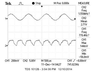
By time-stretching down, we should have doubled our frequency. To check that is is what happened, we input a sinusoidal signal 770.4HZ into our system. Ideally, the pitch shifter should have outputted double this frequency, or about 1.541kHz. As can be seen from the scope, the output signal's frequency was 1.558kHz, which means that there was a 1.1% error. Although the sound could have been cleaner, we were pleasantly surprised with this result. It should be noted that we input a frequency outside our low-pass bound because our function generator was not able to provide a signal with a low enough amplitude that would not cause clipping. To circumvent this, we decided to use a sinusoidal signal that would have it's magnitude partially reduced, so the amplifier would not clip the input signal.
Although we had a partially working implementation of pitching-up capabilities, we were not able to create a pitching-down system or clean up the signal due to time constraints. Pitching-down the signal requires elongating the signal and playing it over the same sampling period. Again, this implementation directly contradicts what most literature on the subject says; however due to our small sampling window resampling does not affect the output pitch as much.
At certain points of this project, we also decided to try and implement basic low-pass, high-pass, and band-pass filters to experiment with the FFT. However, none of these seemed to work. Even after consulting with Professor Land, we could not pinpoint the reason but it is most likely due to an offset of the real and imaginary components and magnitude and phase manipulation.
Safety was one of our highest concerns in this project. No matter what we were doing, safety always came first. This meant always using wire cutters to strip wires, using anti-static mats for MCU placement, never touching bare wire, taking extra care not to short Vdd and ground to avoid frying the MCU, etc. If one of us had ever violated these rules, the other would have to do his best to keep his partner in check.
The project had little to no electrical interference with other groups. There were no wireless communication devices used so there was no radio disturbance. The only problem that our project presented to other groups is that it could be annoying at times, especially when random loud and unpleasant noises came out of the speakers. To avoid angering other people in the lab, we kept the speaker volume to a minimum whenever possible.
For the most part, the project is relatively easy to use. If soldered, the circuit could be condensed very much, making it quite compact and very portable. One thing that would improve usability is a more accessible mic, one that was not flat against the breadboard. This way, the user could bring the mic towards their face rather than having to stoop down to the level of the mic. This change would be especially important if this system were to ever be used in a performance setting. Most people with special needs should be able to use our product relatively easily, but an extendable mic would definitely improve their experience.
Conclusion
All in all, we were not able to implement the pitch-shifting algorithm on the MCU. However, all was not for nothing! We discovered some very important limitations to the MCU, limitations that will hopefully be able help students in the future. The main bottleneck of our implementation of the algorithm was the conversion from rectangular to polar, and back to rectangular coordinate systems in reference to the frequency domain. The implementation of a sine, cosine, and arctangent function operating on a floating point is very difficult to implement in a real-time system in between an FFT and an IFFT. Therefore, in the future, groups should consider trying to avoid this coordinate system switch. If a polar transform could be found, one that allows direct manipulation of magnitudes and phases rather than real and imaginary coefficients, this bottleneck could be avoided altogether (assuming the transform would not be too computationally heavy). However, seeing as how next year a 32-bit microcontroller is being introduced into the class, this bottleneck might be avoidable.
After reading through the list of IEEE standards, we did not find much that we had to adhere to, due to the fact that our system is entirely self contained (i.e. does not use any RF devices, etc.). As for quality standards, our system is not functional, nor is it soldered, so we do not meet those requirements.
Our code implementation did utilize ideas from other codes. The FFTfix code, as well as the LCD and UART code, was directly ported from Professor Land's course website. In addition, the idea behind our phase vocoder pitch-shift algorithm was taken from DSPDimension. Their implementation was in C++ and used a different FFT format, but many of the ideas for our pitch-shift algorithm was based on this implementation. Indeed, we modified their code to implement in C and tested different optimizations on it to see how it sounded. However, they give explicit permission to use their code, under the condition that credit is given to them. We then reverse-engineered their algorithm and attempted a very hacking replacement, as described previously. We do not believe that there are patent opportunities for our project, unfortunately, nor do we plan on publishing.
Ethics were always in our mind. Engineering ethics ranges from safety, to legal infringement, to bothering our classmates in lab. As described above, safety was focused on, and all possible sources of danger were avoided. In addition, we made sure to avoid conflicts of interest. We are not trying to make a profit from our finding, nor do we believe that we have caused others to be financially or publically harmed in any way. We were always honest when discussing the issues that we ran into with Professor Land. We never accepted bribery. We strived to produce something cool and interesting, but we did bring to light some limitations of the CPU that we could not get around. We did improve our technical competence, as much was gained from both the design, as well as the debugging, of the project. We often discussed with Professor Land, as well as a couple other people, ways to improve our algorithms and did look for feedback. In addition, if a colleague in the class had a question that we were capable of answering, we did our best to help them in any way. We did our best to act in the most ethical way possible.
There are not many legal considerations in regards to this project from a safety point of view, but we have been careful to avoid copyright infringement. The whole of the project is self-contained, and could easily be boxed up. In addition, the highest voltage being used in the system in 5V (other than the power supply to the MCU itself), so there is not much risk of danger. This is not an original idea, and we are totally aware of that. We have been very careful to not infringe on any patents, and our list of references is complete.
Appendix
Cost chart
|
Name |
Cost |
|
Power Supply |
5 |
|
Mega1284p |
5 |
|
PC Board |
7 |
|
LCD |
8 |
|
White Board |
6 |
|
Total: |
31 |
Note: we ordered no parts for this project so everything was found in lab. All other components were obtained from lab; hence they were not factored into the budget.
Commented Program Listing
We have two versions of the code, one focusing on the time domain, and one focusing on the frequency domain. We have inserted both:
Division of Labor:
Each group member really did work together for the majority of the project. We worked together to build the hardware, each spending time alone in the lab, each spending time together there as well. As for the software, we sat side by side and coded together. Matt would be on his laptop, and Mashrur would be on the lab computer. Using his computer architecture background, Matt eventually came up with the data management system used in lab, and Mashrur debugged after Matt refused to believe the idea was incorrect. When the deadline came closer, Mashrur branched off into the time domain, and Matt remained in the frequency domain looking for answers. More specifically,
Mashrur:
experimented with upsampling and downsampling the input signal, outputting at different rates, and experimented with the zeroing out different frequencies in the FFT, and different schemes for reflecting the data across the origin in the FFT.
Matt:
experimented with different ways to optimize the code found, including both in the demo code and on the hardware. In addition, he too spent a lot of time trying to zero out different frequencies, only operate on magnitudes while ignoring phases, different hacks to approximate the arctangent function, and things like that.
References:
http://people.ece.cornell.edu/land/courses/ece4760/Math/avrDSP.htm
http://www.jjj.de/fft/fftpage.html
http://www.dspdimension.com/admin/pitch-shifting-using-the-ft/