"A resistive touch screen robot that follows a user-defined path input by drawing on the touch screen.""
We designed and implemented a robot that follows the path drawn on a touchscreen.
The touchscreen is mounted on top of the robot, and once the path is drawn, and the user picks up their finger,
the robot follows the dictated path. The robot will take the path drawn on the screen, and traverse a path within
a 6x9 foot area. This was done because the interface between a robot's movement, and the path being drawn by a user has many unique,
and interesting applications, from robotic drawing to autonomous operations.
High Level Software Design
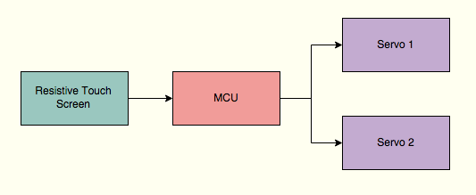
The software for the T-Bot is divided into four core elements. The diagram below describes the overview of the process and is followed by a detailed explanation.
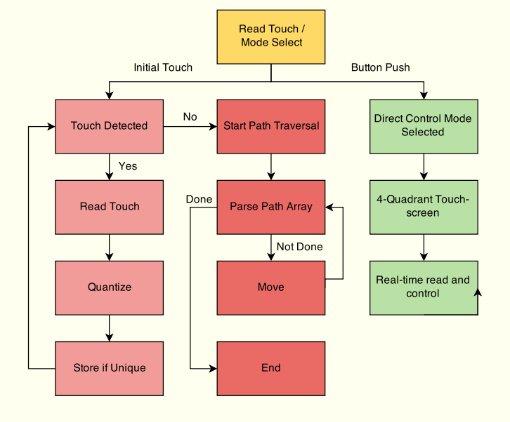
Read Touch / Mode Select
When the MCU is initially turned on it enters this mode. Here it waits to detect a read on the touch screen, polled every 50ms by an interrupt, while simultaneously polling the push-button on PINB5. If an initial touch is detected, the path-following mode, outlined in red, is entered. If instead, the button is pushed, the direct control mode is entered.
Direct Control Mode
This is a fairly straightforward mode where the touch screen is divided into four quadrants and by pressing in the correct one, one can control the robot by moving it forward, backward, left or right. This feature was included for convenient control as well as to allow a remote-control feature if the project was expanded to wireless control in the future.
Path-Following Mode
This is the core operating mode of T-Bot. The image below, illustrates an example path entered on the touchscreen. The path-following mode is activated as soon as a touch is detected on the touch-screen. Once the initial touch is detected, every 50ms, the touch screen is read and the reading is quantized to fit into the 6x9 grid. The parameters for quantization are readily adjustable in the code. If the previous post-quantized reading was the same as the current one, it indicates that we are in the same tile, and for our purposes, the same point, so the reading is not stored. This quantization allows for a faster, but more coarse control. It is required for the open-loop nature of the current system. As part of the quantization and store process some error correction is included. A 10pixel buffer is added to ensure that human entry error when close to the edge of a quantized square is not considered a path reading. The entry process would be greatly aided by a functional LCD underneath the touch-screen. This is a potential expansion to the project.
Once the touchscreen reading is detected to be consistently zero, the path is assumed have been completely drawn and the touchscreen is disabled. We now have an array of path points to work with. The array is parsed for every two path-points. Since this is an open-loop system, there are only two parameters we are controlling: direction and run-time. Each point-to-point movement is thus divided into two steps. The first step is to adjust the heading of T-Bot and the second is to move forward for the appropriate distance.
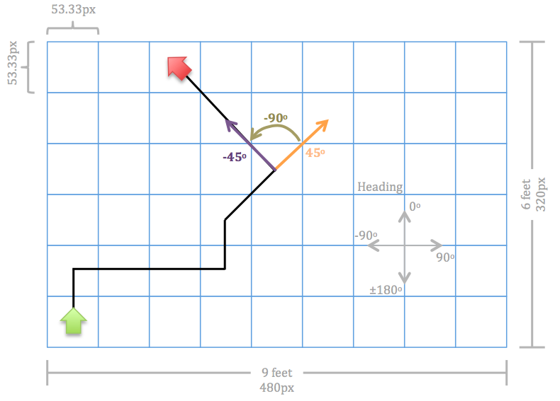
The heading calculations are based off a fixed heading system. As shown in the diagram, the robot is initially considered to be facing "north" which is set to 90 deg. For every point-to-point calculation the angle between the points is calculated and adjusted to fit this heading scheme. Additionally the current heading information for T-Bot is stored. Once the new heading is calculated, the changing in heading is calculated as the difference between the current heading and the new heading. If the heading change is positive, the robot is set to turn right, and if it is negative, it will turn left. Since turns are achieved by turning the servos in opposite directions, the time for the turn is calculated based on the circumference of a full point-turn, the speed of the servos and the actual angle of the turn as just determined.
An example of the heading calculation can be seen in the image below. The robot is at position (5,4) and needs to move to (4,5). The new heading is calculated as arctan((x2-x1)/(y2-y1)). This results in the value of -45 degrees. Since the current heading is 45 degrees, the difference will be -90 degrees, which is the value that will be used in calculating movement time. Although the majority of our cases will only involve turns with a resolution of 45 degrees, this system is equipped to handle the whole 360-degree range of angles and computations. An important corner case to mention is a full 180-degree turn. Conditionals are in place to monitor current heading and change the sign on the 180 degree heading in order to have the fastest turn. For instance, if the robot is at a heading of 90 deg. and the calculated heading is -180 deg., it will realize that +180 deg. is more appropriate and will turn right as expected.
Low Level Software Design
Touchscreen Reading
As described in the hardware design section, the touchscreen is a 4-wire resistive touchscreen. It has two lines, one for X reading and one for Y reading. One end of the line is connected to an output pin and the other end is connected to the ADC. The touchscreen is read by toggling the output pin to high and reading the value from the ADC. Due to the simple, analog nature of the touchscreen, it needed to be tested and calibrated accordingly.
If we were to read the X-coordinate we would want to read the X- pin while setting Y- to high. Similarly, for the Y-coordinate, we set X+ high and read Y+. We read both the high and low bytes of the ADC, although we do not require this level of precision. When tested, we determined that the screen readings ranged from 4,000 to 60,000 in the X-direction and 8,000 to 56,000 in the Y-direction. These were then scaled down to the 320x480 pixel resolution of LCD, although it was not used.
An interesting phenomenon we observed while performing the touchscreen reading was that we needed to repeatedly read the screen thirteen or more times before an accurate reading was registered. Although we could not establish a firm reason for this, a theory would be that there was some level of capacitive build up when performing a reading on one wire which needed to be discharged fully before we could read the next one and multiple reads enabled this to happen. Unfortunately, we were unable to find conclusive evidence that this was in fact the case.
The reading of the touchscreen and the direct control mode are handled by timer 0, configured for 1ms interrupts. The read interval is configurable but is currently set to 50ms. The direct control function operates on the base 1ms intervals.
Servo Control
We used two continuous rotation servos for this project with an operating range of 4.8-6V. The servos work with a standard PWM. However, instead of direct duty-cycle speed control they require specific pulse widths. In order to stop the servo, a pulse of 1.5ms is required. In order to move full speed in one direction, 1ms is sufficient, while 2ms is sufficient in the other direction. Because of this small range for pulse operation, a high-resolution PWM timer was required.
We selected timer 1 which provides up to 16-bit resolution, based on the configuration, and made use of all 16 bits. The pre-scalar was set to 16. The two channels, OCR1A and OCR1B, connected to D4 and D5, were the PWM outputs. The output values were tuned to the desire speed. It is important to note that for forward motion, the two servos will need to turn in opposite directions due to the way the servos are mounted on the robot. The final output values were selected to be 172 for one direction, 202 for the other direction and 187 for stop.
Testing
The general testing approach for the project was to do a high level of unit testing. We made extensive use of the UART and PUTTY to get feedback from the code as well as to test the touchscreen. After the touchscreen and motion control codes were seperated and independently tested, they were compiled as one. We displayed our calculated values as well as time steps to the UART, keeping in mind that the print did produce a delay. Most of the testing ran smoothly and was beneficial to debugging and producing the final product. However, during our use of the UART print statements, we ran into one instance where the motion control code refused to function without a print statement. This was right inside the motion control loop in main and was not an issue that a delay could solve as one might imagine. Since all it took was the printing of a single character, impact on memory and the stack was also minimal. This makes the issue an intriguing one. It may be that the hardware wiring of the UART serial line, somehow interfered with this part of the system.
Code is included in the appendix.
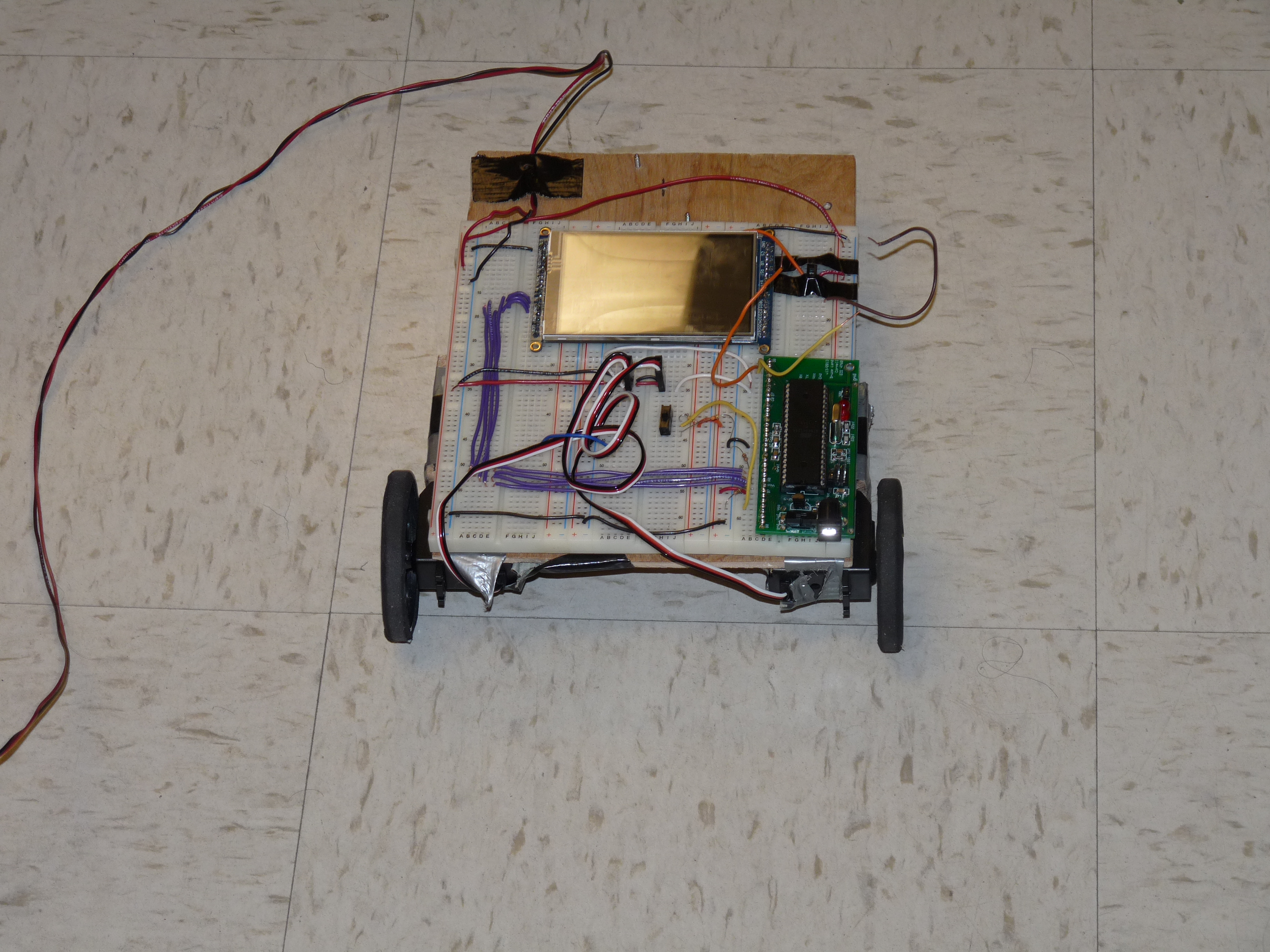
The main concept behind this project was to interface a 4 wire resistive touch screen (TFT LCD) with the ATMega1284P that controlled the direction a robot moved. The microcontroller is connected to the two servos which turn the wheels of the robot as well. The touch screen used was a 3.5" TFT 320x480 with a touchscreen breakout board. Though this board has LCD capabilities, for this project only the touchscreen portion of the device was used. The TFT LCD has a backlite that was set high to VCC because it was always on. The VCC from the LCD was connected to the power supply while ground was connected to MCU ground.
The control signals for the TFT LCD are chip select, command/data, write and read. These were connected to pin C0-C3. The eight data pins are connected to B0-B1 and D2-D7 with D0 and D1 being used for the serial communication. The main concept behind a 4-wire resistive touch screen is that depending on where a user presses on the screen, the resistance changes accordingly allowing the user to pinpoint the x and y location of the touch. To read these values the X+, X-, Y+ and Y- pins corresponding to pins A0-A3 were read. To read the X position of the user's touch, the X-, Y+, and Y- are set to ground while X+ is connected to high. Then the voltage to Y+ is read. To read the Y position, the X+, X-, Y- pins are set to ground while the Y+ pin is set to high. The voltage on the X- pin is then read. Due to a capacitive buildup in the touch screen, the x and y positions were read multiple times(13) before actually being stored to allow time for the pins to reset. The wiring from the MCU to the touchscreen board was wired according to the figure below.
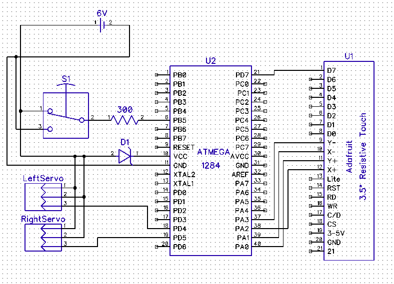
The second main hardware component of the design were the two servos. The servos we used were high torque full rotation. There were two used, one for each of the back wheels while the front wheel was simply a rotating wheel that changed direction according to the direction of the back wheels. The voltage ranges of the servos were 4.8-6.0V where we set the voltage to 5.0V. The torque was 45.8-66.7 oz-in and the speed ranged from 60-70 r/min for 4.8V to 6.0V respectively. The full rotation servos were used for better wheel control. Each servo had three wires: red, black and white. The red wire connected to MCU VCC while the black wire connected to MCU ground. The white wire was the control wire and was connected to the PWM signals. In order to drive the wheels a PWM signal was fed individually to each wheel.
After fine tuning each servo to match up with the other, we fed different PWM signals to each wheel. We first found the PWM signal that made both servos stop turning and used this as our stopping point whenever we wanted the robot to stop moving. Timer 1 was used to achieve this PWM signal. Both servos were programmed in an opposite fashion so that for one given OCR1A/OCR1B value, one wheel turned forward and other one moved backward. Then fine tuning the OCR values gave us the desired rotation speed for both wheels.
Depending on what the OCR1A/B was set to, the wheels rotated in different directions and at different speeds. The closer the value was to the stopping point, the slower the wheels rotated. The values chosen were 172 and 202 for to move the robot forward, backward, left and right. The stopping point was when OCR1A and OCR1B was set to 187. In order to turn the robot right, the right wheel was set to spin backward while the left wheel was spun forward. This meant OCR1A and OCR1B were set to the same value of 202. To turn left the opposite was used. All the connections to the MCU went through a 300ohm resistor as well. The interfacing between the robot, MCU, and resistive touch screen is shown in the figure below.
The robot was made mainly of wood. To a single flat piece of wood, we fastened two servos and the three wheels with screws. In addition the MCU and touch screen were attached to three breadboards that sat on top of the robot. There were two methods we used to power the robot. The first was using a battery pack to power both the MCU and servos allotting different voltages to each. Four AA batteries were used to do this. However, the batteries drained extremely quickly (~45min) therefore we chose to use a different method. The second method was to use the power supply set to 5V and ground with an extended wire to power the robot directly. This method was much more reliable and thus chosen to be used. A picture of the robot is shown in the introduction.
We implemented two additional switches, one that powered the MCU on and off, thus turning the robot on and off and another switch that was implemented to distinguish which mode the robot was in. The first mode, as described in the software section, was where each of the 4 quadrants on the touchscreen were mapped to the robot moving right, left, forward or backward. The second mode was the free draw mode where whatever the user drew on the screen was traversed by the robot.
Testing the hardware required several steps. Once the robot itself was built, the two PWM signals were fed to the servos to determine if the wheels were rotating at the same speed. To determine this we both counted the number of rotations of each wheel along with displaying it on the oscilloscope to make sure the period of the PWM to both servos was the same. Then both switches were implemented to test whether the modes were actually switching. We also implemented an LCD screen and used the uart to aid our testing using several print statements. Once the code was set we actually tested the robot to see how well it followed directions. To map the size of the touch screen to the actual floor the robot was traversing, we divided the touch screen up into the area we had on the floor. This value was based on a parameter defined in the code. We then put tape on the wheels so they would not slip on the flooring and adjusted the PWM signals to ensure the robot travelled in a straight line.
Demo Video:
Additional Demonstration:
Speed of Execution
For our project, in the path mode, the speed of execution is dictated by the length of the path that is drawn on the LCD. The wheels turn at 24rpm which is the ultimate parameter for the speed of execution. In the direct control mode, the motion of the robot is very receptive to controlling the direction. It is very receptive because the robot is constantly polling for the direction command. When a direction command is sensed the robot moves, and when the user removes their finger, the robot stops as it is sensed that there is no command for direction present.
Accuracy
In the path mode, the robot is able to successfully traverse the path drawn. When the user draws 90 degree turns, or a straight path, it is seen that there is a 100% success rate of reading the direction as forward, left, or right. When drawing a 45 degree on the LCD for the robot to follow, there is a success approximately 7 out of 10 times. When read incorrectly, the direction is read as a 90 degree turn. The methods to improve upon these metrics are spoken about in the conclusions.
The accuracy of the path drawn with only straight, and 90 degree turns in the forward direction returns a physical path that is completely consistent with what was drawn. When the robot finishes its execution of this type of path, it is about 3-4 inches off of the predicted path. When the path is drawn as a closed loop on the LCD, the robot's final position is one foot away from the starting point.
For the direct control mode, the accuracy is very high. Almost instantly as you place your finger in the quadrant dictated for a particular direction, the robot moves in that direction. Also, as your finger is removed it stops its motion. This is due to the direction being checked every 1ms.
Safety
The robot is very soundly built. Structurally, with the motions that the robot is built to handle, it will remain stable. The voltage used for this robot is also low at 5 Volts so this is not to be a concern for the user. All wiring was cleaned up such that the user was able to handle the robot with ease, and without danger to themselves, or the robot.
Interference
For this project we did not have to worry about inference with most other groups' designs, with the exception of those that were also designed to be run on the floor. With these designs we shared limited floor space and had to be cautious about running into the other projects or their creators.
Usability
The T-Bot is fairly usable. The robot is very responsive, and intuitive. However, the lack of a working LCD makes it somewhat difficult to understand what the user is drawing and what they can expect the robot to do. The means to switch between the modes of operation is simple, and the procedures for each mode are easy to master. For those that are visually impaired this project is not very user friendly.
The final performance of our project met all of our basic expectations. The robot was ultimately able to accurately track the path, scale the path, and convert it to the necessary wheel rotations. When beginning this project the ultimate goal was just to have the robot have the ability to follow the drawn path, and as this was achieved we thought we could build upon it. When we began the project and selected our touchscreen we were not aware of the fact that the touchscreen and converted LCD libraries did not use the same control board as the previous version sold by the Adafruit. This change in Adafruit's hardware made it impossible for us to use the converted C libraries used by ECE 4760 students in the past. This limited our use of the LCD below the touchscreen as an added component to the user interface. Next time, we would make sure that the libraries were compatible so less time could be spent configuring the LCD and touchscreen. Doing this would allow us to not only improve the user interface, but spend more time expanding the capabilities of the system built. Some potential direction for additional capabilities is the addition of more sensors such as infrared to add object identification abilities. With the addition of object identification, and subsequent avoidance, and/or plotting, the possibly for the expansion of this project grows substantially.
Standards
The C code in our project abides by the C Language standards set by the ANSI and the 1666-2011 IEEE Standard System Language. The only standards that were used related to using UART. We always used the baud rates specified in the datasheet, which were multiples of 9600. We also use the UART code provided by the ECE 4760 course website.
Intellectual Property
The design and implementation for this project were based upon the knowledge acquired from ECE 4760 at Cornell University. The datasheets for the components used are attached in the appendix section found below. The website was designed in its entirety by the project creators.
Ethical Considerations
The touchscreen controlled robot created in this project is consistent with IEEE Code of Ethics and does not harm one's health, safety, or welfare of public, and does not disclose promptly factors that might endanger the public or the environment. When reporting the successes of our project we have been honest and realistic in stating all claims and estimates based on the data that we have collected. We are sure to be realistic in stating the claims or estimates based on our data so we are able to help improve the understanding of technology. We took this improvement in the understanding of technology upon ourselves as we are qualified to undertake the endeavor of the project, and we see ourselves as people that are able to assist those around us with growth in this area. We wanted to report on all aspects of the project, including successes, and difficulties so we could receive and give honest criticism of technical work. When paying for all of the materials that were used for this project we did not receive any bribery, and all outside resources used are provided in the appendix. As a diverse team of women we strongly stand by the fair treatment of all persons, and stood by this though the entirety of our project.
Legal Considerations
For our project there are no legal considerations. All previous work done by others in support of the success of this project, such as documentation, have been properly cited in the appendix. In addition, our project is safe, so in its proper use it does not endanger or harm the user, or any surrounding bodies.
Future Improvements
For future expansion of the project, several steps can be taken. The first is to integrate a closed loop system which utilizes sensor feedback. Two types of feedback would be beneficial in this case. A radar or similar sensor that can relay position, as well as encoders or continuous rotation potentiometers would be useful in doing PID for more precise servo speed control.
The closed-loop system would provide more accuracy in movement which would translate to more accuracy required in the input method. By quantizing the touch screen inputs to a higher resolution grid (squares of 5-10 pixels), we can add algorithms to detect standard paths, drawing errors and extrapolating the entered motion. Additionally, re-writing the LCD libraries or wiring it into an Arduino would enable the use of the LCD for all user input as well and more accurate drawing with visual feedback.
From a mechanical standpoint, the accuracy of wood-based construction is extremely limited. A 3D printed base would be much more accurate. Additionally, the initial orientation caster wheel in the front of the current model has a fairly significant influence on angle of the path. Replacing it with two more servos or two wheels on separate axles would improve performance.
Contact Information:
Mahitha Rachumalla - mrr222@cornell.edu
Varnika Atmakuri - va86@cornell.edu
Danielle Regis - dar324@cornell.edu
Code:
main.c
TouchScreen.c
TouchScreen.h
Data Sheets:
ATMega1284
Adafruit 3.5" TFT Touchscreen
4-Wire Touch Controller
Continuous Rotation Servo
Wheels
Vendor Sites:
Adafruit
All Electronics
Code / Designs Borrowed from Others:
Initial touchscreen code, before heavy modification: Original TouchScreen.c
Background Research Sites:
4-Wire Touch Robotics
4-Wire Touch Video
4-Wire Touch Basics
4-Wire Touch Sparkfun
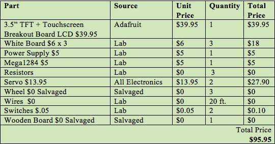
Parts Cost: