ECE 4760 Final Project
Shiva Rajagopal (svr24) and Richard Quan (rq32)
Introduction
"The sound and experience of drums...
Any time, anywhere,
with any object."
-Project Soundbyte
It's Friday night and you're hanging with your friends at home. There are no parties tonight and you have seen everything on Netflix already - you're bored out of your minds. One of your friends pulls out his portable roll up piano keyboard, starts making random songs out of boredom. "Let's make the next big hit, guys!" You all get excited. One of your friends sings along, making the lyrics as she goes. It's starting to sound like a real song, but it's missing a beat. You have the perfect idea of the drumbeat that should go along with the song, but all you have around you is two pencils. Luckily, with Drums Anywhere, you have all you need to drop the beat for your song!
Drums Anywhere is the simplest solution to making a great drum beat at short notice. Using two simple 3D-printed boxes that you can attach to any stick-like object, you can strike any surface to instantly output the sound of drums through your speakers. Using a clap sound for one box, and a snare drum sound for the other, Drums Anywhere can output the drum sound you want, even with accurate amplitude corresponding to the force of the hit!!
This is an all-new design that costs a fraction of what a drum machine costs, and brings an intuitive and extensible design to what was once a bulky and static set up. Drums Anywhere uses an ATMega1284P Microcontroller and a variety of sensors and hardware to accomplish its purpose, and puts a spotlight on new, accessible technologies such as 3D-printing. This is the first revision of Drums Anywhere, and there is plenty of opportunity to extend this design to include more features, such as more sensors, more drum voices, and perhaps a wireless design.
See a demonstration in the Results section!

High-Level Design
Overview
The project stemmed from a desire to make real drum sounds more accessible to all. Drums sets and drum machines are immensely expensive, and usually out of the price range for a music enthusiast who simply enjoys creating drum beats at short notice. Our project brings together analog circuitry and filters with digital concepts, such as hardware timing, interrupts, and a user-friendly interface. We made a concerted effort to use as inexpensive parts as possible to make this system accessible to all. The system is as simple as possible: the user simply has to plug in speakers, turn on the system, and start drumming.
Logical Structure Block Diagram
The logical structure of our system is shown below:

Hardware/Software Tradeoffs
One of the biggest considerations we made during this project was how much we wanted to balance using cheaper hardware and compensating using the software. We also encountered some tradeoffs when choosing what types of hardware to use. Since our primary aim with this project was to make the system as cheap as possible, we wanted to offload as much of the complexity of the system to the software as possible. We debated using hardware that would simplify our software component, or using a more complex hardware component that would also complicate our software, but for a lower cost. We elected for the latter option, as it added versatility to our design and the use of our project while still remaining well within the computational power of our microcontroller. This tradeoff, while requiring more complex hardware, also made our system more robust. This will be explained further in the Hardware section.
The ATMega 1284P microcontroller has more than enough timing and
computing power to keep up with the system to make the drums real. We
are able to program the microcontroller such that our system is
robust and does not trigger multiple plays with one single hit. This
is through knowledge of human abilities to repeat a hit to keep our
system from unrealistically playing multiple hits in an unacceptable
timeframe. This was a tradeoff of using the hardware we used, as the
likelihood of accidentally triggering unrealistic intervals for drums
was greatly increased. We had to add extra complexity using timers to
mitigate this issue, but the complexity was still well within the
abilities of the microcontroller.
User Interface
The user interface was one of the most important components of this
project. We wanted to make our system as similar to a drum kit as
possible: The user simply has to sit down, grab the sticks, and
create the beat. When the user powers on the device, some initial
setup occurs within the microcontroller, but this takes no more than
5 seconds. The system uses an industry-standard stereo audio plug,
making it easy for the user to plug in any speakers they have, or
even headphones if they want to practice alone. Once the user has
plugged in some form of speakers, they can attach the boxes to
whatever object they have around, including their hands if necessary,
turn the system on, and start playing. The system is capable of
running from a 9V battery, making this system extremely portable.
The LCD serves very little functional purpose in this revision of the
system, only showing the name of the system, the two voices
corresponding to each box, and the microcontroller's amplitude
reading from the Analog-to-Digital converter corresponding to the
most recent hit. However, it does give the user familiarity with the
system, especially if it is their first time.
Standards
Our project does not use very many industry standards, as very few
are required to run this system. The main standard we use is the WAV
audio standard to store our audio bitstream. The WAV standard is a
Microsoft/IBM file format that encodes audio as a stream of bits. We
use 8-bit 22kHz files in this project. All interrupts are
asynchronous, and the bitstreams are stored in program memory, so no
communication protocols are necessary. We use a standard 3.5mm TRS
connector for stereo audio output to any computer speakers or
headphones.
Copyrights/Intellectual Property
In order to convert our sound files to a series of 8-bit values readable by the microcontroller, we made use of Guilherme (William) Kalfelz's (Wusik) WAV2Code program, available here. Wusik's program takes in all .wav files in a folder and outputs a header file with all of the 8-bit values which we could then output using a PWM channel. Our system does not infringe any of his copyrights, and we are very grateful for his making this program available to the general public.
Hardware
Hardware overview
As mentioned in the high-level design section, we made our hardware more complex to guarantee more versatility. This project requires one copy of each system for each extra sound the user wants to output, including the flex sensor system, the microphone system, and a box. The microcontroller software can be modified relatively easily to handle more inputs. The entire system can run on the 5V Vcc supply from the microcontroller, which is stepped down from a 9V supply. We modified our op-amp circuits based on what gave us the most reliable signal for our use cases, as we will discuss further in this section. Future designs will include a smaller box for more compactness and versatility.
Hardware Design
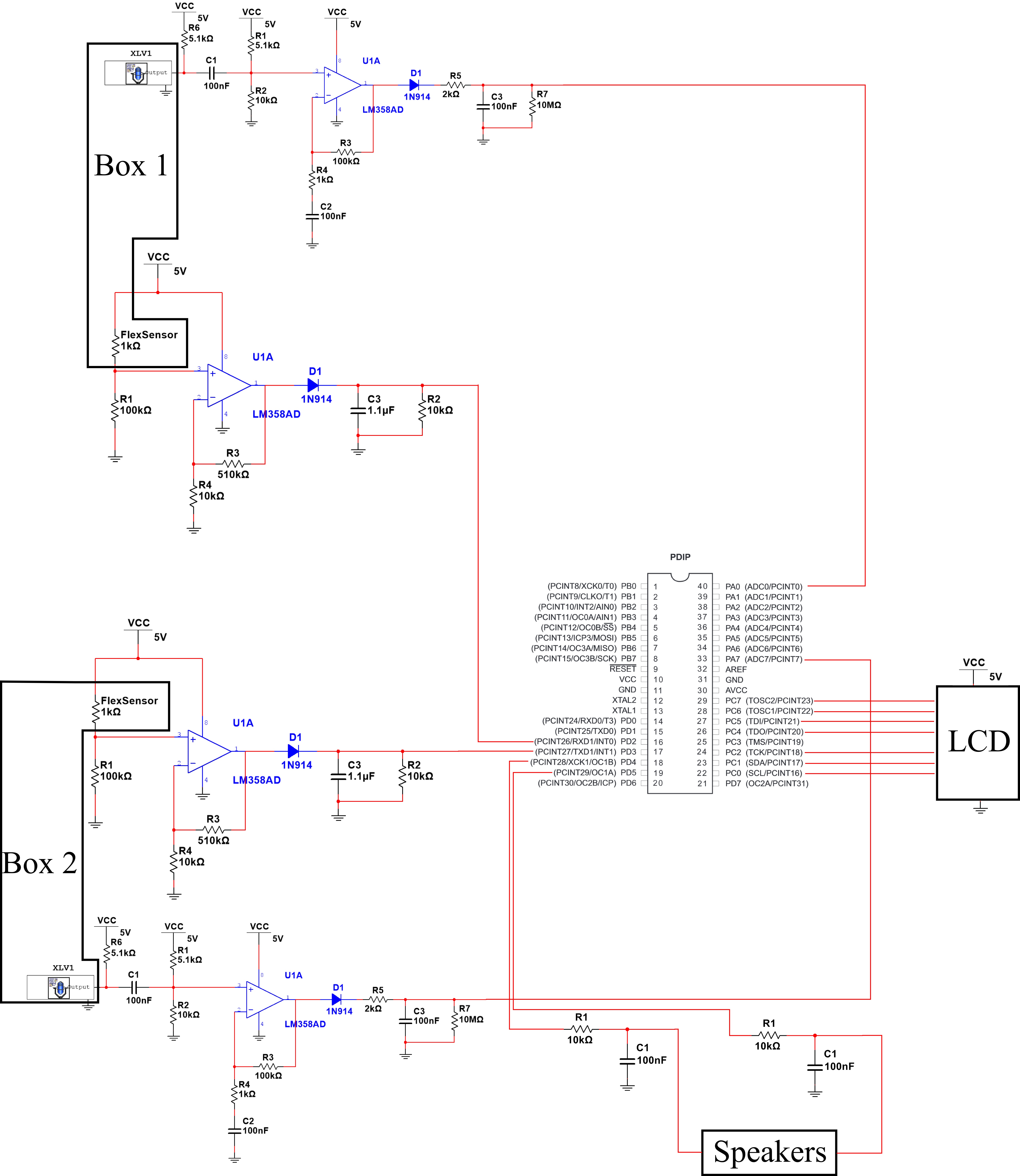
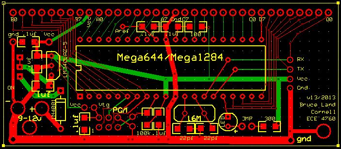
The overall schematic for our system is shown below, including the schematics for all subsystems and how they connect to the microcontroller. This diagram shows direct connections to the pins of the microcontroller for descriptive purposes and to correspond to the software more clearly. For this project, we used a custom target board, available from the ECE4760 Home page. See Appendix B for more detailed schematics of the subsystems and the target board.
Sensor Box
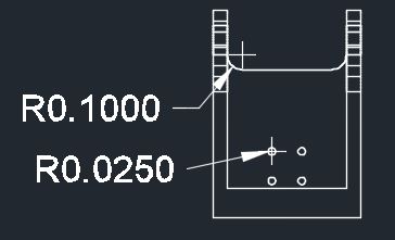
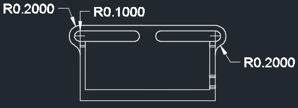
Our sensor box is a 3D-printed object that was designed in AutoCAD. The Dimensions and the CAD file are available in Appendix C. We created the box to be attachable via two-1" Velcro straps, and to have four small holes to handle each of the two wires required by the flex sensor and the microphone. The holes were made such that 26-AWG wire could fit through. We 3D printed the box using Acrylonitrile butadiene styrene (ABS). ABS is a very strong plastic, and is slightly flexible. This means that our box is strong and not rigid enough to break under strong force. The top two holes are spaced exactly to fit the spacing of the flex sensor headers. This enables us to solder the wire on the box surface, and leave the flex sensor suspending. This enables the flex sensor a wide range of motion when the box is hit on a surface, and the flex sensor circuit can take care of the rest. The bottom two holes have small wires running through and are soldered to a microphone inside. The microphone is protected and attached to the box by electrical tape. This gives the microphone a small level of shielding against the sound from outside the box, enabling better isolation and making the amplitude readings more correlated to the force of the box rather than the surroundings.

Flex Sensor
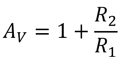
The flex sensor, a Meas-Spec LDTM-028K, was used as the hit detector. The flex sensor offers us no numerical data, and simply serves to inform us when a hit has occurred. As mentioned before, the flex sensor is suspended within the box, and therefore has space to move around. The schematic for this circuit is located in Appendix B. The circuit that follows uses an op-amp with gain to trigger a large enough rising edge to trigger the microcontroller's external interrupt. We use a non-inverting op-amp configuration to apply gain to our signal. The op-amp has rail voltages of 5V and ground. The gain for the circuit is given by:
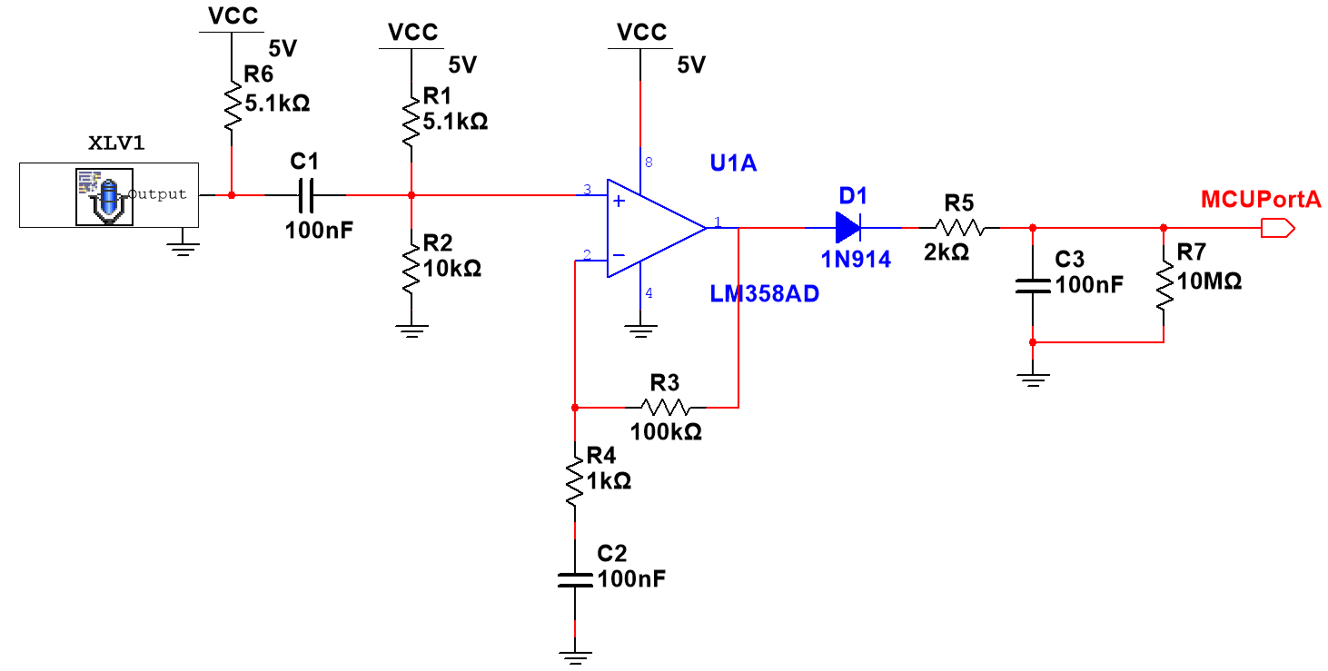
Microphone
The microphone circuit is designed to give us a range of input voltage that we can use to correspond to numerical values in the Analog-to-Digital converter on the microcontroller. The schematic for this circuit is located in Appendix B. We first take the output from the microphone and use a 100nF capacitor as a DC block, so that we remove any DC noise from the signal. We then We then use a voltage divider to add our own DC signal to create a baseline for our sound. Using a 5.1k resistor and a 10k resistor, we get a baseline of about 1.7V, which is added to the AC component from the microphone input. This will be important later in the circuit. From this voltage divider, we input the signal to a non-inverting op-amp gain circuit. The gain of the system is 101, as we can see from the equation in the Flex Sensor section. The added capacitor helps to add a small amount of filtration to the signal, which is simply to denoise the circuit and ensure that we have less variation based on the surrounding noise. After the microphone signal is amplified, we send it through a diode. The 1.7V step-up from before is important now, as we know that our diode will be past threshold and will let our signal through reliably. This also helps us to get a cleaner signal input for our microcontroller, only having positive voltage. Finally, we use a low-pass filter to cut out some high-frequency content that will not be necessary in the signal, using a time constant RC = 0.0002. This cuts off frequencies above roughly 800Hz. We then use a sample holder to ensure that our signal holds close to its value long enough to be accurately sampled by our system. We use a very large resistor here to ensure that we get a wide dynamic range for our inputs.
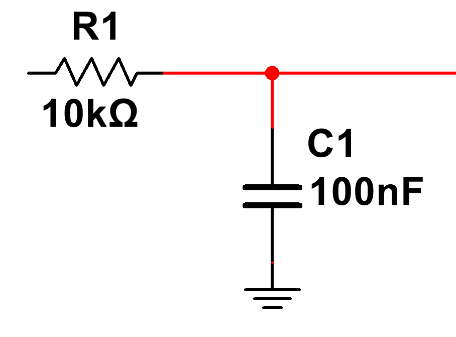
Low-Pass Filter for Sound Output
In order to clean the output PWM signal from the microcontroller of any noise, we use a passive low-pass filter before we output the signal to the speakers. We use a filter with time constant RC = 0.001, with a cutoff frequency of roughly 160Hz. The sounds of a drum are very low in frequency, so this seemingly aggressive cutoff frequency is actually very suitable for our project. The schematic for this filter can be found in Appendix B. This filter does not add excessive delay to our circuit, and produces a much less sharp sound with fewer clicks. We use two of these filters, one for each of the PWM channels we are using for the sound output.
LCD
The LCD is used as an informational tool. The connections for the LCD are visible in the system diagram Appendix B. The LCD takes in Vcc and ground inputs, as well as a contrast input that is based on a 10k trimpot we use, wiping between 0 and 5V to set the display contrast. The controls for the LCD, (EN, RS, and RW), are then set using three more bits from the MCU's C port. Finally, we have 4 wires creating a 4-bit data bus, which is how the LCD gets its data.
Software
Software overview
Our code for this project was written in a way to maximize modularity and encapsulation in order to allow easy extensions to this system as well as a way to isolate errors during debugging. The code includes initialization of interrupts to capture flex sensor data from the drum boxes, use of the microcontroller analog-to-digital converter (ADC) to convert the analog microphone data, the formula we used to translate microphone amplitude into volume for the speakers, drum sound .wav samples to be played by the speakers transformed into C code, and code to run the LCD and have it display a welcome message and amplitude data. We used interrupts instead of polling to capture sensor values with minimum system latency.
External Interrupts
Each of our drum sounds are triggered by external interrupts from our flex sensors to signify that our drum boxes have sensed an impact. To do this, the interrupt registers are set at initialization so that our drum sounds play on a rising edge from the voltage of the flex sensors i.e. the flex sensors have been bent enough by an impact on our drum boxes to create a voltage spike similar to a logical 1, close to 5V. When this happens, we can assume the drum boxes felt a significant impact and we play our drum sound. Competing interrupts are not an issue because interrupts are disabled while each interrupt service routine is still occuring. We have also debounced our interrupts as discussed below in the Safety Timers section.
Safety Timers
The state diagram below describes our debouncing method for multiple interrupts occuring
at the same time. When the system senses an interrupt from the drum boxes and thus plays
the drum sound, the microcontroller starts a timer that counts for 20 ms. The system does
not accept the interrupts until the end of the 20 ms, a time period much too short for most
humans to hit the drum box multiple times, but long enough for us to avoid voltage spikes
due to noise during an impact.

Analog-to-Digital Conversion
We embedded microphones into our drum boxes to determine how loud our output drum sound should be. The stronger the drum box impact, the louder the sound is for the microphone. When a drum box triggers an interrupt for our system, the amplitude from the microphone is read by the system and mapped to a multiplication factor for our sound output described later. To determine a numerical value for the sound's amplitude, we run the microphone's analog output into the microcontroller's onboard ADC. Although the ADC can only read from one port at a time and thus one drum box at a time, we have set the ADC read rate at an extremely high sample rate of 125,000 Hz so this is not noticeable to the user at all.
Sound output
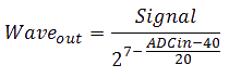
To simulate drum sounds, we used freely distributed drum sounds from across the Internet and an open source converter, Wav2Code, to convert the audio into C code that represented time samples of the amplitudes of the .wav file. The C code sound waves are then stored and read in from program memory. Another timer is set up in fast PWM mode to output to our speaker. We modify our PWM wave's amplitude based on the stored sound waves to output the sound on the speaker according to the equation below. While the denominator appears to be complex math, it is simply a mathematical model for a bit shift. Shifting the output based on a linear change in the input amplitude actually modifies our amplitude to model human hearing better, as human hearing reacts to logarithmic changes, not linear changes. This makes our drum amplitude changes more realistic. When the sound is finished playing, we use flag variables to signify that the system can resume and not act unpredictably.
LCD
The LCD was mostly used as a static display. When the display initializes, we use the LCD library to output three static strings to the LCD, containing the name of our system, and the two voices that the boxes currently correspond to. From there, we use the program's main loop to simply print the most recent amplitude read by the microphone on the most recently hit box. This mostly gives the user a general idea of what force on the box corresponds to different output amplitudes. All conversion is done inside the code, but for a first-time user, the LCD is helpful to get acquainted with the system. The LCD library is slow in general, so it is important to keep our LCD usage to a minimum, which we ensure by only letting the LCD update when no ISRs are running.
Other Required Libraries
These three headers contain necessary functions and declarations for using the ports and features of the Mega1284 microcontroller.
These standard C headers are necessary to implement the logic and data structures needed in the program.
These headers are required for doing the math required to calculate speaker amplitude.
These headers enabled the functions we needed for outputting data through the LCD.
This header holds the recorded sound waves in char arrays to be outputted to the speaker.
Results
Overall Performance
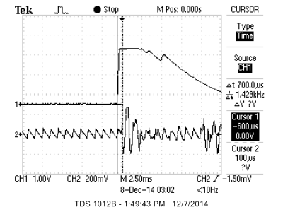
The system performs very well, and has extremely low latency. As we can see from the oscilloscope trace below, the system only takes 700 microseconds from the initial box hit until the sound starts being output. This includes the time it takes to trigger the external interrupt, switch the analog-to-digital converter to the correct port, perform the analog-to-digital conversion, and begin the sound output. This is well below the threshold at which human hearing can notice a distinct latency in the system, making our system very viable as a product. The sound output was extremely clear, as can be seen from the demonstration video. The boxes and their use of Velcro made for an easy-to-use assembly, and is very versatile as to the objects it can be attached to. The Velcro we used was extremely sturdy, and sometimes unwieldy, but this would be easy to modify, as the box straps are capable of handling any type of Velcro that is 1" wide or less. The amplitude response of the system acted as expected, and the system's ability to display useful information to the user helps make the system more user-friendly. The wires and the soldering of the system are sturdy enough to stand up to the force of the drumming, and the use of computer speakers made it easy for the system to be adjustable for a variety of settings. There are certainly ways to improve the stability of the breadboard set up, as we can see from the demo video that the plugs are prone to falling out sometimes, but for most use cases we can say that our system performs very well.
Flex Sensor performance
The flex sensor and the circuit performed very well, as expected. The flex sensor stayed sturdily in the box, as we were able to solder the wire through the holes in the box, and the sensor remained suspended. This led to us having stable, reproducible results for flex sensor input. As we can see in the first graph, our raw flex sensor signal can be weak, noisy, and unpredictable. However, using our flex sensor amplification and filtration circuit, we are able to get the signal on the bottom, which produces a 3V signal that only triggers when the flex sensor hit is hard enough. The 3V is enough to trigger the microcontroller's external interrupt reliably, leading to us having a very reliable and clean method of knowing whether the box has been hit or not. The diode in our circuit ensures that we do not have any excessive negative voltages going into the microcontroller. This is especially important because the flex sensor is capable of swinging the voltage either way as it settles, and too much negative voltage can cause major problems with the microcontroller. Our filtration part of the circuit is able to avoid double signals from the flex sensor effectively, as we can see in the bottom trace as well. The flex sensor was able to trigger hit signals for a variety of microphone amplitudes, as we can see from the second scope trace below. This ensures that our system did exactly what we planned: We could confirm a hit with the flex sensor, and get variable amplitudes from the microphone.
Flex Sensor Raw Input vs. Filtered and Amplified Signal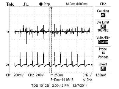
|
Flex Sensor output vs. Microphone Output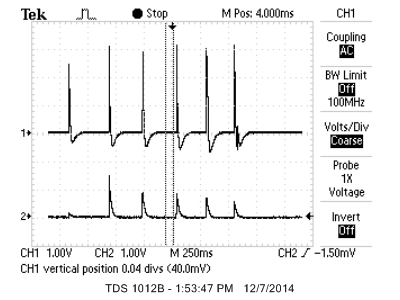
|
Microphone Performance and Accuracy
The Microphone assembly performed very well for the range of hit forces that our system could be put through. The DC offset gave us a good baseline for the microcontroller to compare to. As we can see in the first trace below, the microphone's dynamic range was about 1.7V, which gives us a good space for converting to digital values and converting them to realistic amplitudes. The microphone was isolated from outside noise well enough to be passable in a variety of environments. When testing the amplitude readings while directing noise directly at the microphone, we did find that the microphone was not as well-isolated as it could be, sometimes creating louder output than expected for the hit as a result. However, this could also be useful as a feature. Getting inaccurate amplitude readings like this required a lot of surrounding noise, and if the user is in an environment as loud as this, maximizing the output might be useful. As we can see in the trace to the right below, the amplitude of the microphone was roughly correspondent to the eventual amplitude of the speaker output. The few microphone spikes with no speaker output are shown to demonstrate that microphone amplitude does not translate to a sound output when the flex sensor does not trigger.
Microphone Dynamic Range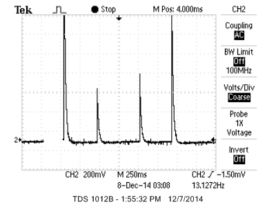
|
Microphone Amplitude (top) and Speaker Output (bottom)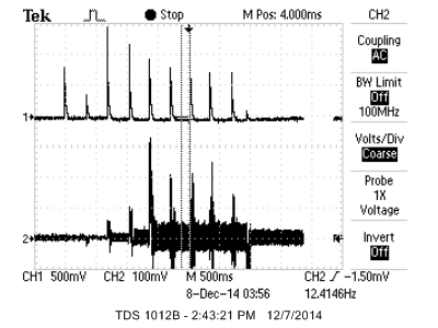
|
Sensor Boxes
The ABS plastic used to 3D-print the drum boxes were easily able to stand up to the force applied to them when hitting a hard surface, such as a table. This tells us that the boxes are resilient, as a table is the hardest surface that we expect the user to hit the box on. Anything softer, such as someone's lap or a softer table, will also cause a drum beat, but will not cause as much stress on the box. After putting the assembly together, we found that the box dimensions were excessively large for the hardware we needed to fit inside. A second revision of the design could move the flex sensor higher in the box, making space for the microphone to fit below, enabling us to also solder the microphone through the side of the box, like the flex sensor. This constraint would enable us to cut the length of the box in half, and only require one Velcro strap loop, as opposed to the two we have currently. The boxes were functional, but not optimal.
Safety and Interference
As with all projects, we had to ensure safety with Drums Anywhere. Electrically, the system is extremely safe, not using voltages above the 5V Vcc source that is used by the rest of the system using the microcontroller. The user's drumstick, whether it be a physical object or the user's hand or wrist, does not ever come close to the electricity that is required by the sensors. The system is well-insulated, and does not pose a threat of electric shock to the user. Our boxes are also not heavy or sharp, and therefore pose no physical risk if they are accidentally thrown, in case the box slips off the user's stick. Our project in its current form does not use any wireless technology, and therefore does not cause any interference with other electronics. A future design might see an attempt to make the system wireless, but any interference would be taken into consideration before it was developed, and we would try to use existing technologies, such as Bluetooth.
Conclusion
Summary and Possible Improvements
The system overall performed as we expected it to. The latency of the system was very minimal, and the output of the sound corresponding to the box hit occurred seemingly instantaneously. The output of the amplitude corresponded to the force of the hit in a very natural way. Our use of simple operations in the microcontroller code combined with the reliability of our sensors made for a strong, robust system. The sensor boxes feel sturdy and accomplished their purpose very well. Our project accomplishes its purpose of making drum sounds available any time, anywhere. This allows anyone, whether they are drummers, music enthusiasts, or anyone who simply wants a drum beat, to simulate the feeling of drumsticks with a cheap, simple assembly.
Using small quantities of the required parts, we were able to keep our costs for this system very low, especially during the development stages when we were experimenting with different sensor assemblies. We were able to save money on 3D-printing as well, as Cornell's Rapid Prototyping Lab printed our boxes for free, since they were for academic purposes. Printing these commercially out of the same material would not be prohibitively expensive, as our box could be printed for $5 in its current form. This cost could be minimized with a redesign as discussed in the Sensor Boxes section of Results. With or without the free boxes, however, our project is significantly cheaper than any drum machine in existence, and takes a unique approach to creating real drum sounds at short notice.
One other advantage to our project is the extensibility. We are currently using external interrupts on the microcontroller, of which there are only three on the board. However, we could easily use pin change interrupts for the same purpose, of which the microcontroller has 32. This enables us to add features to the system like enabling a box that a user could place on their feet to simulate a bass drum. This could easily be accommodated by the memory of the microcontroller as well, as our current storage of drum sounds does not use more than 10% of the microcontroller's internal program memory. This could enable us to add many more drum voices, and a button-based interface to changing the voices corresponding to each box.
We would have liked to clean up our breadboards and use more efficient layouts. Currently, we only use one side of each op-amp PDIP. Consolidating this assembly could halve our number of Op-Amp PDIPs and let us use one less whiteboard. In addition, our project would be more optimal with a smaller, rearranged box, but this would be an easy fix, as we have a much better idea of how to fit the parts together now.
Standards
The only standard we used in this project was the WAV sound standard. Through use of Wav2C from Wusik, we were able to convert our WAV files into an 8-bit 22kHz stream of bytes that we could output from program memory with ease, keeping the fidelity and structure of the WAV file. This standard does not need licensing, and was very easy to use in our project.
Intellectual Property/Legal Considerations
The only part of our software assembly we cannot take credit for is the use of Wusik's Wav2C. Wusik owns the copyright to this program, but he makes it available for free online, along with its source code. There is no particular license attached to this program that we could find, but we are not using this program for profit. Therefore, we do not believe our use of Wusik's program infringes any intellectual property.
There is certainly opportunity for patents on this project. To our knowledge, there is no system in existence like ours that enables the user to attach an object to a stick and produce realistic sounds like those from a drum kit. However, for this to occur, we would need to ensure that we are not infringing on any license that Wusik uses for his Wav2C program. Alternatively, we could build our own Wav2C system so that we do not need to worry about legal violations. Otherwise, there are no legal considerations to worry about for our project, as we do not use any wireless transmitters, and do not need special licensing for any part of our project.
Ethical Considerations
In developing this project, we followed the IEEE Code of Ethics, being careful in the development of our project to engineer our product in a responsible manner. We investigated the possible safety concerns that come along with this project, and determined fully that our project would be safe even if accidents were to occur. We minimized risk in order to be consistent with public safety and welfare in mind. In addition, we sought honest criticism at every stage of the development of our project, including from Bruce Land, our TA Tahmid, and from our classmates to make our project better. At many points, we had small errors in our code, or in our design, and have acknowledged the contributions of all those involved in this project. We have been honest and realistic in the abilities and limitations of our project throughout. This is exemplified by our statements about how the project is limited in its current form, but there is plenty of room for extensibility. We have also been honest with the drawbacks of our project in terms of usability, size, and ease-of-use. Finally, we have sought to improve understanding of technology through our project. Our project is technologically simple, and we make all of the information available to the public in order to encourage others to build similar products if they are interested. This project is a good example of how simple hardware and software can be combined to create a musical application, and we hope that this reaches those who have similar interests and want to build similar systems.
Appendix A: Commented Listing of Code
You can download our commented source code here: DrumsAnywhere.zip
Appendix B: Schematics
Target Board (source)
System Diagram: (click for higher-resolution)
Flex Sensor:

Microphone:
Low-Pass Filter:
Appendix C: Drum Box CAD Model
Download AutoCAD file here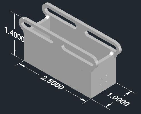 |
 |
 |
 |
Appendix D: Component Cost Breakdown
| Part | Vendor | Quantity | Unit Price | Total Price |
|---|---|---|---|---|
| ATMega1284 | Lab stock | 1 | $5 | $5 |
| LCD | Lab stock | 1 | $8 | $8 |
| Breadboard | Lab stock | 3 | $6 | $18 |
| Flex Sensor (LDT0-028K) | Lab stock | 2 | $2 | $4 |
| Microphone (CMA-4544PF-W) | Lab stock | 2 | $1 | $2 |
| 9V Power Supply | Lab stock | 1 | $5 | $5 |
| 3D Printed Boxes | Cornell Rapid Prototyping Lab | 2 | $0 | $0 |
| Velcro | Lab stock | 2 | $0 | $0 |
| LM358 Dual Op-Amp Chip | Lab stock | 2 | $0 | $0 |
| Speaker Connector | Lab stock | 1 | $0 | $0 |
| Two-pin header | Lab stock | 2 | $0.20 | $0.20 |
| Resistors | Lab stock | 24 | $0 | $0 |
| Capacitors | Lab stock | 12 | $0 | $0 |
| Diodes | Lab stock | 4 | $0 | $0 |
| 10kOhm Potentiometer | Lab stock | 1 | $0 | $0 |
| Wires | Lab stock | Too many | $0 | $0 |
| Tape | Lab stock | Not enough | $0 | $0 |
| Total Overall Cost | $42.20 |
Appendix E: Task Delegation
Shiva Rajagopal |
Shiva and Richard |
Richard Quan |
|---|---|---|
| Software Design | Assembly | Hardware Design |
| Sound Output Interface | Website Design | 3D-Printing Boxes |
| Microcontroller Debugging | Wiring of Flex and Microphone Circuits | Box Assembly |
Appendix F: References
Appendix G: Acknowledgments
We would like to thank Bruce Land for use of his lab, and all of the parts for this project. We also thank him for pointing out the simple fix when we were struggling to remember basic concepts. ECE4760 was an excellent class, and we enjoyed it immensely.
We would also like to thank Syed Tahmid Mahbub for helping us through the sound output section of the lab, as his advice to use onboard sounds greatly simplified our design and created higher fidelity drum sound output than we would've been able to synthesize.
We would also like to thank Guilherme (William) Kalfelz (Wusik) for the WAV2C program we used to convert our drum sounds to char arrays. His program made our project much easier and sped our development immensely. Find his Arduino/Microcontroller website from the link in the References section above.