"A laptop with diplay and keyboard capabilites that runs RetroBSD, a UNIX OS"
project soundbite
Introduction top
For our 4760 final project, we created a miniature laptop called iPicUNIX that runs RetroBSD, a port of BSD. The microcontroller is mounted on the Fubarino SD board. The laptop has a TFT as a 2.8' display and keyboard both enclosed within a 3D printed encasing. There are sample programs that allow the user to execute and edit. RetroBSD allows for a full UNIX environment with a built in C compiler to satiate the user's hacking pleasures. The total development cost is within the $100 threshold.
Our mixed interest in operating systems and firmware encouraged us to create iPicUNIX. We saw this as a unique opportunity to create a product that drew on content that we learned both within this class and beyond its scope. This project allowed us to develop both our hardware and computing skills in an unfamiliar realm of system integration and kernel and driver manipulation.
High Level Design top
Design Rationale and Project Idea Incubation
We initially had interest in developing a miniature software defined radio (SDR) that operated on a short wave band. However, after consulting faculty and careful consideration, we realized that developing a functioning SDR from the hardware side would be unrealistic in the final project's time span. We then chose to switch to create a UNIX run laptop. Our greatest motivator to build iPicUNIX was fun. We found the idea to be extremely interesting, and felt our final product would be something both of us would enjoy using.
Logical Structure
The system was structured as follows: commands were inputted into the Microstick II based PIC32 from a keyboard. The inputs were decoded and pushed via UART to the Fubarino. The Fubarino contains the BSD kernel which is stored in the internal Flash memory and the filesystem which is mounted. Programs can be run and altered off the Fubarino. An SPI connection to the TFT was maintained by the Fubarino.
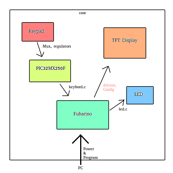
Figure 1: Logical Structure
Hardware / Software Trade offs
With the iPicUNIX, our system was largely implemented in software. The nature of an Operating System lends itself to software, making this an obvious choice for its implementation. For the keyboard, we abstracted out the logic from our Fubarino board, using a second PIC microcontroller to do software debouncing matrix scanning and communication with the Fubarino in software, and actually building the keyboard and signal muxing in hardware. The TFT was controlled by a built in ILI9341 TFT control chip.
Relevant Standard
RetroBSD is an open-source project, free for use and alteration. RetroUSB's creation and the vast bulk of its existence is due to Serge Vakulenko. We used an application called pic32prog, also written by Serge Vakulenko, to flash code to the internal flash of the Fubarino.
Hardware Design top
Fubarino
The Fubarino runs the PIC32MX795F512H microcontroller. This proved to be a good fit for the specifications of this project as it met all memory requirements to run RetroBSD and is a member of the MX series, a requisite for this project. The MX795 has 512K Flash memory, 128K RAM with a 80MHz 32-bit MIPS core. Likewise, the RetroBSD uses 128 KB of RAM to run applications. Like the PIC32MX250F128B mounted microstick, the Fubarino can be powered through USB and is directly operable with 3.3V devices with no regulation necessary. The Fubarino contains 45 Digital IOs with the majority possessing up to 5V tolerance. Additionally, there are 15 10-bit Analog pins. There are two hardware serial ports (UARTs) plus a serial connection through USB that operates at 12Mbps. A microUSB reader with SPI protocol is used for storing the filesystem. Also, a 2.8” LCD TFT was used as our display. It has 240x320 resolution with 16-bit color. The TFT was interfaced through SPI although it has parallel capabilities as well. To set SPI up, the pins IM1, IM2, and IM3 are set high by soldering shorts onto the pads on the back.
Keyboard
For our keyboard, we purchased a iPazzPort KP-810-16, a mini wireless keyboard, with the intention of disassembly the keyboard and hijacking the internal PCB to use as our keyboard, getting the pins from the pushbutton matrix before they were debounced, encoded into USB, and wirelessly transmitted. However, we found that the pins going into the IC were too close together to accurately probe while also pushing switches, and that the effort of figuring out the matrix would be too high, when we could just make our own matrix. So that is what we did. We took a solder board, and created a keyboard of 65 pushbuttons, 13 wide and 5 tall. Then, we soldered these all into a matrix. Purely by chance, the rubber overlay with the keys drawn on from the keyboard we bought happened to fit, so we were able to use that.

Figure 2: Creating the keyboard

Figure 3: Switches inserted
First, we attempted to use the PIC32MX250F128B to directly scan the keyboard, taking advantage of the code we had already written for lab 2, and creating a 2D array of ASCII code to be indexed by the result of the scan and sent via UART as chars. Despite almost all of the keyboard working fine, 2 columns simply wouldn’t work. After several hours of debugging (probing pins, switching keyboard lines to make sure the keyboard itself wasn’t at fault, trying external pulldown resistors, making all inputs outputs and vice versa, etc), however, we found that 2 of the pins we were attempted to use were not actually valid I/O pins, and that the PIC32MX250F128B pinout on the ECE 4760 main page was actually fairly erroneous, listing both RB12 at pin23 and RB6 at pin15, both of which were not actually I/O pins but actually DC voltage pins. In order to get around this limitation, we employed two 8 pin muxes to hook up the column pins of the keyboard to the PIC. In this way, we were able to cycle through the mux selects in order to mimic reading all the inports, and the seeing when one of the mux outputs went high, and recorded the select at that time in order to index into our software array. This way, we only needed to use 13 pins on the pic, instead of the 18 from before.

Figure 4: Connecting the prototype circuit
Case
As a finishing touch on our project, we wanted to create a case to house our internals. To design the case, we used AutoCAD 2016. The case consisted of 5 parts: a base, to house the fubarino, the keyboard circuit and the keyboard; a screen housing, to hold the TFT; a screen frame, to lock into the housing; and 2 hollow hinges, to route wires from the TFT to the base internals. The design was actually quite complicated; designing the hinges to allow for wires to go through, designing the base to allow for the screen to open up past 90 degrees, making tabs on the base in order to allow the keyboard to snap in, etc. After completing our design, we reached out to one of the professors in the ECE department, Joe Skovira, who allowed us to use the 3D printer in one of his labs in order to print our case. After correctly calibrating the printer, we were able to print the parts without much problem, and assembled the case.

Figure 5: Open case

Figure 6: Side profile
Software Design top
Software made up the vast majority of our project. The kernel and filesystems are the core structures behind RetroBSD. The main exterior program was the keyboard decoder and debouncer. The configuration files, drivers, and add-on C files were either edited or created to run RetroBSD on the Fubarino.
Keyboard decoder and debouncer were written on the Microstick. This code was based off our previous code we had written, namely our keyboard scanner and debouncer from lab 2, and our uart code from lab 4. We organized the code into two main threads: the uart thread and the key thread. In the uart thread, we simply would take characters from a global buffer which was filled by the key thread, and outputted it via UART at 115200 baud. The key thread handled interfacing with our keypad, and worked using nested four loops to output high at each keyboard row sequentially, each time cycling through every mux select possibility and reading the mux outputs to see if a connection had been made between a row pin and column pin, and if so, recording the row and column values. These values were then used index into a 2D array of ASCII codes, which after debouncing using the 4 stage FSM we used in Lab 2, were place into the buffer as chars.
The configuration files, drivers, and add-on C files were either edited or created to run RetroBSD on the Fubarino.
Keyboard decoder and debouncer were written on the Microstick.
Results top

Figure 7: Prototype of project
Our project was quite an elaborate undertaking and, as a result, was unfinished by the end of our given timeline. We had successfully modified and flashed retroBSD to the fubarino, and written our own code to interface with the I/O pins, simply blinking an LED. In order to interact with the minicomputer, however, we had to use our computers as the console, and connect to one of the UART ports on the Fubarino to boot and control and see the console. This was because we weren’t able to get our keyboard circuit to interface with the Fubarino. In addition, while we were able to interface with our TFT using the SPI, we weren’t able to get the console to output onto it. So while we were able to fully interact with the BSD operating system, we weren’t able fully realize our portable retroBSD experience we sought to create.
Speed of Execution
In our project, everything we did had considerable responsiveness. Even though the 80MHz of the PIC32 seems slow today, the computers of the time when BSD 2.11 was released (the version of BSD that retroBSD is based on) in 1992 had about that clock speed. Our keyboard we created was also very responsive, with no visually detectable input lag. We expect, however, that the limitations of SPI and TFT technology would see considerable slowness when trying to output the console quickly; however we didn’t get far enough to see if that we be the case.
Safety
For our lab, we were dealing with fairly nominal voltage levels, maxing out at about five volts. The case we made was out of ABS plastic, so any user would be protected even if something went wrong, and the keyboard had a rubber cover to separate the user from the internal circuitry.
Interference with other peoples design
Without any powerful electromagnetic or audio outputs, our device would not interfere with any other design.
Usability
Because we weren’t able to connect the keyboard to the main board, or get the TFT to act as a console, we couldn’t use the device as it had been originally intended, as a portable laptop-like device which could be programmed on the go. However, using a computer to interface with it allowed us to still write programs and execute them, as well as executing simple graphical examples on the TFT. Operating the iPicUNIX system requires a basic understanding of UNIX and the kernel. In program vi and cc allows for the user to create, edit, and compile files on-site, allowing the user to change the system’s function in minutes.
Conclusions top
Summary
While we did not attain our initial target of constructing a fully-operational laptop-like UNIX computer, we made significant headway in our time working on the project. Both members had little to no experience in operating systems; we viewed the iPicUNIX project as a learning opportunity in a very interesting realm of low-level systems within the confines of microcontrollers. The enormous progress made in the final week of the project shows that proof of concept is not only possible but likely given our greater understanding of the dynamics of the operating system.
Future Improvements
There are a variety of improvements that can be made to create a functioning laptop. Hardware wise, a modular printed circuit board is necessary for the keyboard circuit to fit in the currently designed case. The circuit on the solder boards, specifically the wiring, does not permit the keyboard to rest securely within the case. The TFT and its respective wiring fits snuggly within its allotted space and functions as expected. Implementing VT100, a video terminal that supports ANSI escape codes, is an area worth exploring to add functionality to the keyboard. Converting the wiring from the TFT to Fubarino from solid core to ribbon cables will reduce the firmness opening and closing the laptop screen.
On the software side, the project needs to have a screen that displays the console. A direct fix to this is to modify the gpanel-spi driver file to allow for dual UART and SPI connectivity to allow for programming from the external system and displaying the console onto the TFT simultaneously. Our attempts at this approach did not come to fruition; however, more research into the drivers and configuration files is necessary. Additionally, extra program demo files besides blinking LEDs would be resourceful to exhibit the capability of the operating system and Fubarino. An interesting program would be using an MP3 file to project a series of sounds through a microphone. Such a program would require a DMA-driven, Vref DAC output and the corresponding driver. This sound feature will give the iPicUNIX system functions closely resembling a computer.
Standards
PSerial Peripheral Interface (SPI) was used as a communication protocol between the Fubarino and TFT for outputting data (SDI) to the display.
Universal Asynchronous Receive Transmit (UART) was used as the communication protocol between the PIC32MX250 and the Fubarino for the keyboard.
Intellectual Property Considerations
The only code not written by us are properly cited and from Serge Valukenko and the ECE4760 staff.
Ethical Considerations
Throughout the scope of this project, we constantly complied with the IEEE code of ethics. We are conscious that our project is novel in that it is the only attempt at a portable laptop-like system running retroBSD. iPicUNIX is designed for the recreational hacker's personal enjoyment and utility from having the power of BSD in a small, embedded setting. Our project was devised such that it cannot be used to cause physical harm or distress to others. Throughout the duration of the project, we have been honest and open with our results, code, and analysis and pledge that any conflicts of interest shall be brought to light. We encourage everyone to explore different technical projects that they have interest in. Despite our lack of operating system knowledge, we found the challenges and successes from this project to be extremely rewarding.
A specific list of the IEEE ethical code can be found here: IEEE website.
Legal Considerations
The license for retroBSD allows for redistribution of the source and binary, as long as the copyright notice is kept among distributions, and the creators can’t be used to promote products derived from the software without explicit permission. In the scope of our project, these guidelines were followed, including the addition of the copyright notice in our modified kernel configuration file.
Appendices top
A. Schematics
Our schematics were generated using a fully licensed version of Eagle 7 on Ubuntu 14.04.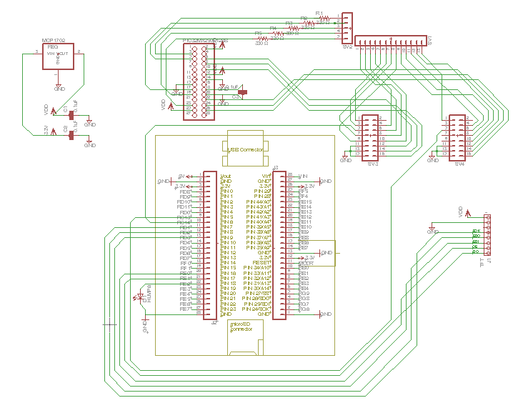
Figure 8: A diagram of the entire hardware setup and network
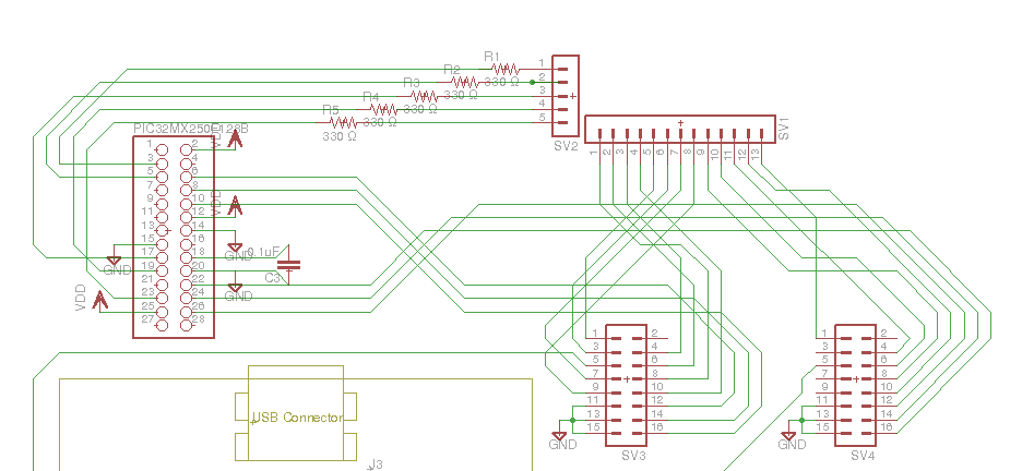
Figure 9: Keyboard Circuit
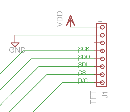
Figure 10: TFT Pinout
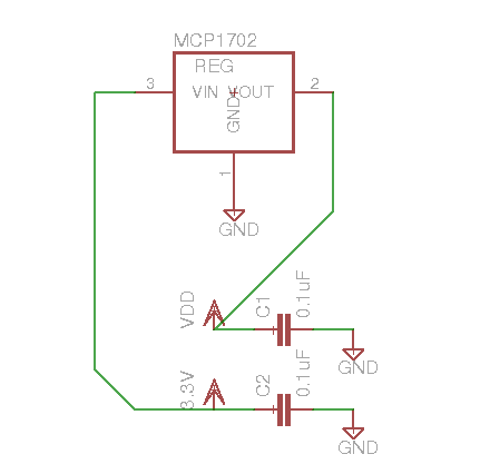
Figure 11: Voltage Regulator
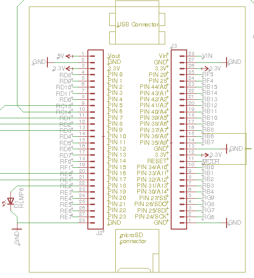
Figure 12: Fubarino Closeup

Figure 13: CAD rendering of the case
B. Cost Details
Part Number |
Vendor |
Quantity |
Price |
Total Cost |
Fubarino SD |
Microchip Direct |
1 |
$30 |
$30 |
2.8” LCD TFT ILI9341 |
Adafruit |
1 |
$30 |
$30 |
PIC32MX250F128B |
Lab stock |
1 |
$5 |
$5 |
Solder Board |
Lab stock |
2 |
$2.50 |
$5.00 |
P02368H mux |
Lab stock |
2 |
N/A |
N/A |
header socket |
Lab stock |
1 |
$0.05 per pin |
$1.40 |
3D printed case |
Lab stock |
1 |
N/A |
N/A |
Total: $75.90
D. Code Listing
Kernel and Filesystem Code
Keyboard Code
Schematics
C. Distribution of Work
Will |
Cyrus |
keybord hardware |
display configuration and drivers |
keyboard code |
LED code |
3D printed case |
circuit layout |
configuration modification |
website |
Acknowledgements top
We thank Professor Bruce Land and TAs for guiding and teaching us throughout the project and course.
We would also like to thank Serge Vakulenko, the creator of RetroBSD, for make a wonderful open-source project. We alos would like to thank members of the RetroBSD blog for their help.
Additionally, we would like to thank Joe Skovira for letting us use his 3D printer to print our case.
