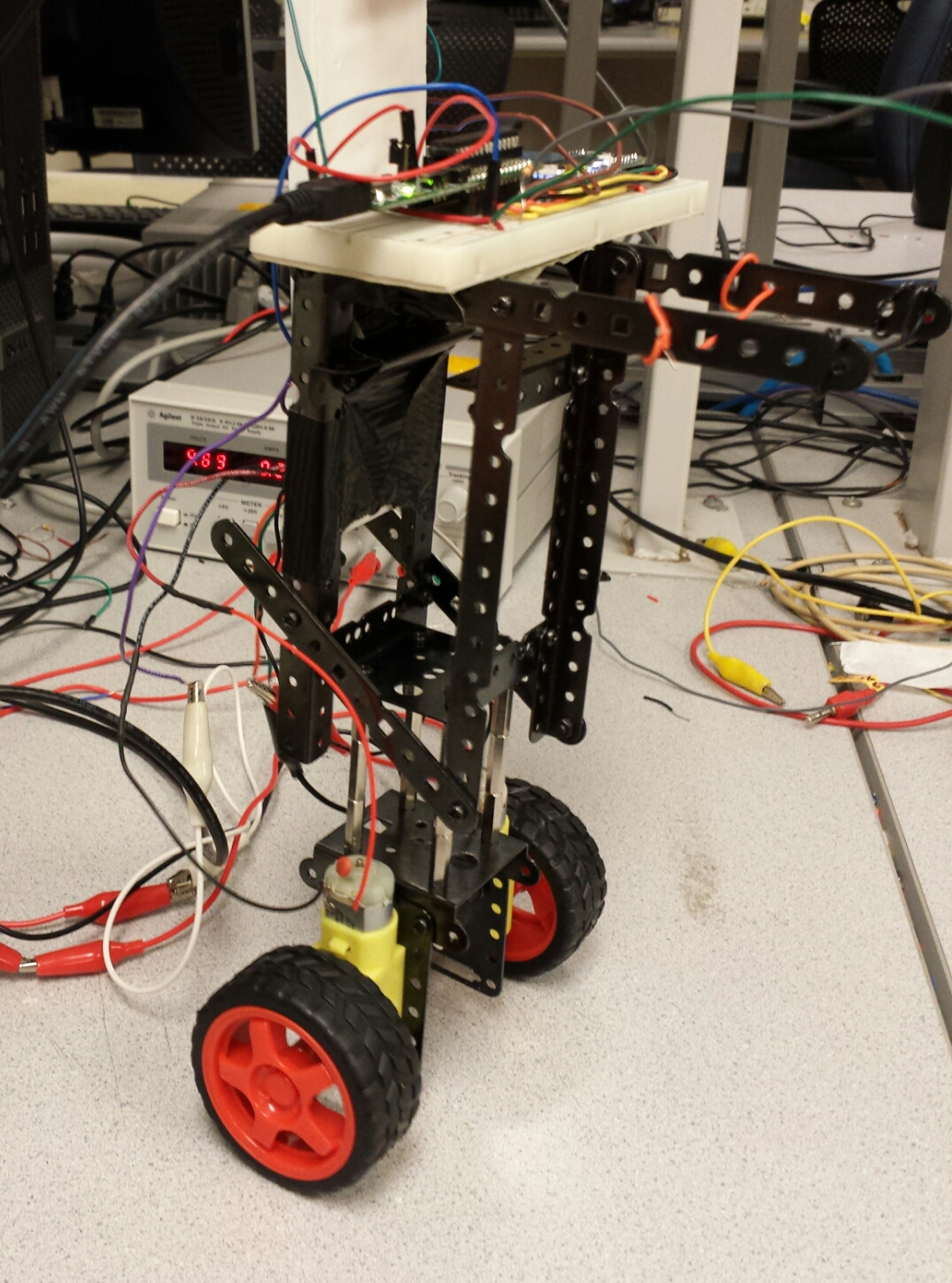
"A self balancing, two-wheeled, inverted pendulum robot."
project soundbyte
The early popularization of personal transportation with portable hoverboards has inspired and paralleled the recent development in hands-free transportation systems such as self balancing scooters. Further, advances in Artificial Intelligence and Robotics has forwarded the creation of surprisingly capable robots that can navigate the world autonomously. These technologies are made possible by research in dynamic control systems, that has recently produced amazing results.
Such research and technologies have inspired us to create our own self-balancing robot.
In this report we present the design, construction, results, and concluding thoughts that have culminated in our final project for the course ECE 4760: Designing with Microcontrollers, a PIC32 operated self balancing robot. The robot, or balancebot, consists of a tower structure that houses the PIC32 with peripherals, an inertial measurement unit, and a motorized drive system. The PIC32 receives tilt information from a gyroscope and accelerometer and produces a pulse-width modulated directional signal to drive two motors sitting at the base of the tower. The motors drive wheels that position the robot so as to counteract the tilt of the tower and thus balance the structure. The chassis, motors, and wheels were salvaged from an Arduino robotics kit. We bought gyroscope and accelerometer chips as well as an H Bridge. All other components were sourced from the ECE 4760 lab space.
High Level Design top
Overview
Our design can be divided into the hardware and software. The hardware involves sensors and controllers. The software uses the sensor data as input to produce outputs for the controllers.
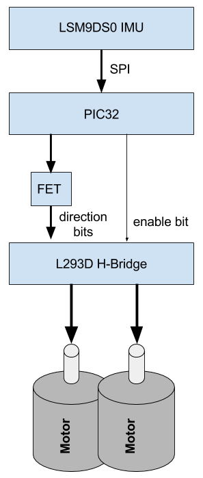
We obtain accelerometer and gyroscope sensor values from an inertial measurement unit (the Adafruit LSM9DS0 chip). The PIC communicates with the LSM chip using the Serial Peripheral Interface (SPI) protocol. The PIC32 use these values to determine how to drive the motors, and sends two signals: one pulse-width modulated (PWM) amplitude and a direction control bit. (See figure below) The PWM signal allows us to control the strength of motor response, and the direction control bit allows us to vary the direction of the response.
In order for the robot to drive in both direction, we implement our motor control with an h-bridge. The h-bridge allows us to apply the PWM voltage in either direction across the motors, which is essential for balancing.
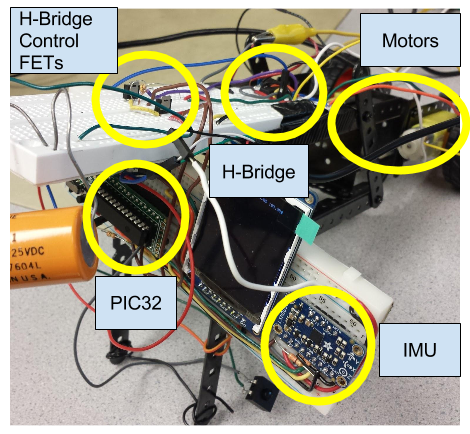
We used a TI L293D H-Bridge chip. In order to vary the power output of the motor, we PWM the enable pins on the L293D. The duty cycle on the PWM controls how long the L293D is enabled and driving current through the motors. In this manner, the PIC32 can control both the direction and power with which to drive the motors. The major components and connectors in the robot are displayed in Figure 1.
In our actual implementation of the Balance Bot, we used two direction bits, which are mutually exclusive (as done in software), one for each motor. We also used MOSFETs in order to drive the H-Bridge direction control with a 5V source (which the PIC cannot supply). Moreover, we connect a 6V source to the H-Bridge, which powers the motor (and, importantly, maintains isolation between the drive circuitry and the PIC). For both the 5V and 6V supply, we simply use the table power supply, which wires sufficiently long enough to avoid interfering with balancing. Figure ??? shows our implementation of the block diagram above.
The robot is a closed-loop system, and uses sensor filtering from the raw IMU values to more accurately determine the current state of the robot.
Background Math
In developing the balance bot, we considered the dynamics equations that represent the behavior of the system. These turn out to be very complicated and ould not necessarily lead to a better performing robot. Here are several links to more complete reports with in-depth analysis of the dynamics involved (http://web.mit.edu/2.737/www/extra_files/andrew.pdf, http://resources.sei.cmu.edu/asset_files/TechnicalReport/1999_005_001_16784.pdf). In our project, we take an explicitly more experimental approach.
Our Controller
In order to convert our pitch approximation from out sensor reading into an effective motor output to balance the robot, we utilized a PID controller, which is comprised of three different terms designed to stabilize a wide variety of dynamical systems. The proportional term demands output proportional to the error in the desired state, the integral term “learns” past errors and demands output to correct them, while the derivative term fights overshoot by predicting future change and acting against it to maintain the desired state. This is a linear controller, and we found that it worked quite well when we tuned the P, I, and D values appropriately. We go into significant detail about how these controls work and what results they gave in the Software PID Controller subsection, and Results section. (https://en.wikipedia.org/wiki/PID_controller)
Hardware/Software Tradeoffs
There were few instances of us having to make hardware/software tradeoffs, yet several are noteworthy. One example is the use of two control bits that are mutually exclusive. Instead of using a not-gate, we simply used two outputs from the PIC. This allowed us greater confidence in avoiding ever setting both control bits to high at once, and was simple to implement as we had many free I/O pins. One other such tradeoff was the multiplexing of the gyroscope and accelerometer data on a single line. The LSM has two separate pins for each, and yet we were unable to configure the PIC to read on a single SPI channel from two different pins. Fortunately, the acceleration and gyroscope readings were always transmitted synchronously, so we merged both pins from the LSM into a single data line for the PIC to read (see more in the hardware section for the LSM).
IEEE, ISO, ANSI, DIN, and Other Standards
Our robot utilized the SPI standard for communication to our sensor peripherals. We use UART for serial communication between the PIC and our lab computer to read data. We do not explicitly use other protocols in our robot’s operation.
Patents, Copyrights, and Trademarks
Self balancing technology has been in development for many years. Various patents and restrictions are currently in effect which would greatly inhibit the commercialization of our own interpretation of a balancing robot. These patents include US 6302230 B1, US 20020063006 A1, and many others, including international patents. We do not plan to commercialize our project in any form as this robot was created purely for educational purposes.
Hardware top
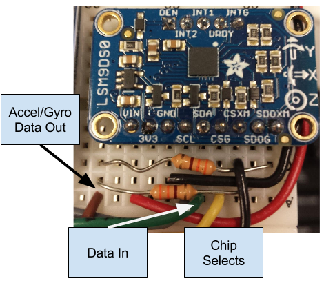
The hardware for our robot was designed procedurally in stages. First we set up communication between the LSM9DS0 gyroscope/accelerometer. We used an SPI interface to both configure the LSM and to read the gyro and accel values. We use 5 lines from the PIC in total: clock (SCL), chip select for acceleration (CSXM), chip select for gyroscope (CSG), data in (SDA), and data out (SDOXM and SDOG). In addition, we provide standard 3.3V power and GND to the LSM.
"It should be relatively straightforward for someone else to build our balance bot from our design documentation"
As mentioned in the hardware/software tradeoffs, we were limited to one pin on the PIC to read IMU data, yet there are two data out pins for acceleration and gyroscope readings. We could have simple connected both of the outputs directly to each other with a wire, and read that common wire with the PIC. However, if we accidentally set both of the chip selects LOW (they are active low), then the two outs would create a short and potentially destroy our LSM. We protect against this situation by connecting both of the pins serially to 300 Ohm resistors, in parallel with each other. The actual LSM circuitry is displayed in Figure ???.
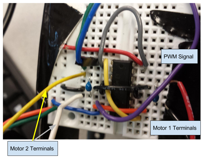
Once the SPI communication worked, we moved on to interface with the L293D H bridge. This required generating one PWM signal and two direction control signals. Direction signals are mutually exclusive, except when changing directions during which time they may both be momentarily low. Testing revealed that the the logic high signal coming from the PIC32 was not high enough to trigger the H bridge. We used two MOSFETs to supply a constant 5 volts controlled by the PIC32 to the H bridge. The PIC sent a PWM signal to the L293D over its enable pins in order to modulate the speed of the motors. Lastly, the motors were directly connected to the H bridges output ports.
We initially considered using a single H-Bridge to control both of the motors at once, as it would cut the amount of circuitry roughly in half. However, the specifications of the L293D were not sufficient to drive both motors at once, at max capacity. Fortunately, the L293D has two full h-bridges, and so we were able to devote one h-bridge to each of the motors.
The TFT display on the robot was purely for debugging purposes and as such is not a necessary component of the Balance Bot. During development, we used it to display the data read from the IMU, variables related to the PID control, and the actual PWM output to our motors.
It should be relatively straightforward for someone else to build our balance bot from our design documentation. We have provided detailed block diagrams with pin labelings as well as the source code and parts used.
During our design of the Balance Bot, we attempted various things which did not end up working out or remain in our final design. Early in the design of our hardware, we attempted to create our own H bridge from components provided in the lab. We found that our H bridge did not support the current draw our motors demanded, and lack of PFETs meant that there was a large voltage drop across the NFETs connected to the source voltage resulting in less driving voltage for the motors. We also worked with alternate motors and gearboxes to find a balance of speed and torque for our robot. An iterative design strategy allowed us to quickly find faults, whether they be electrical, mechanical, or software related, and implement solutions for them.
We would like to note that excluding the H-bridge and the IMU, all of the other components we salvaged or found otherwise in the lab. We are particularly proud of the performance of our robot from what scrap parts we found.
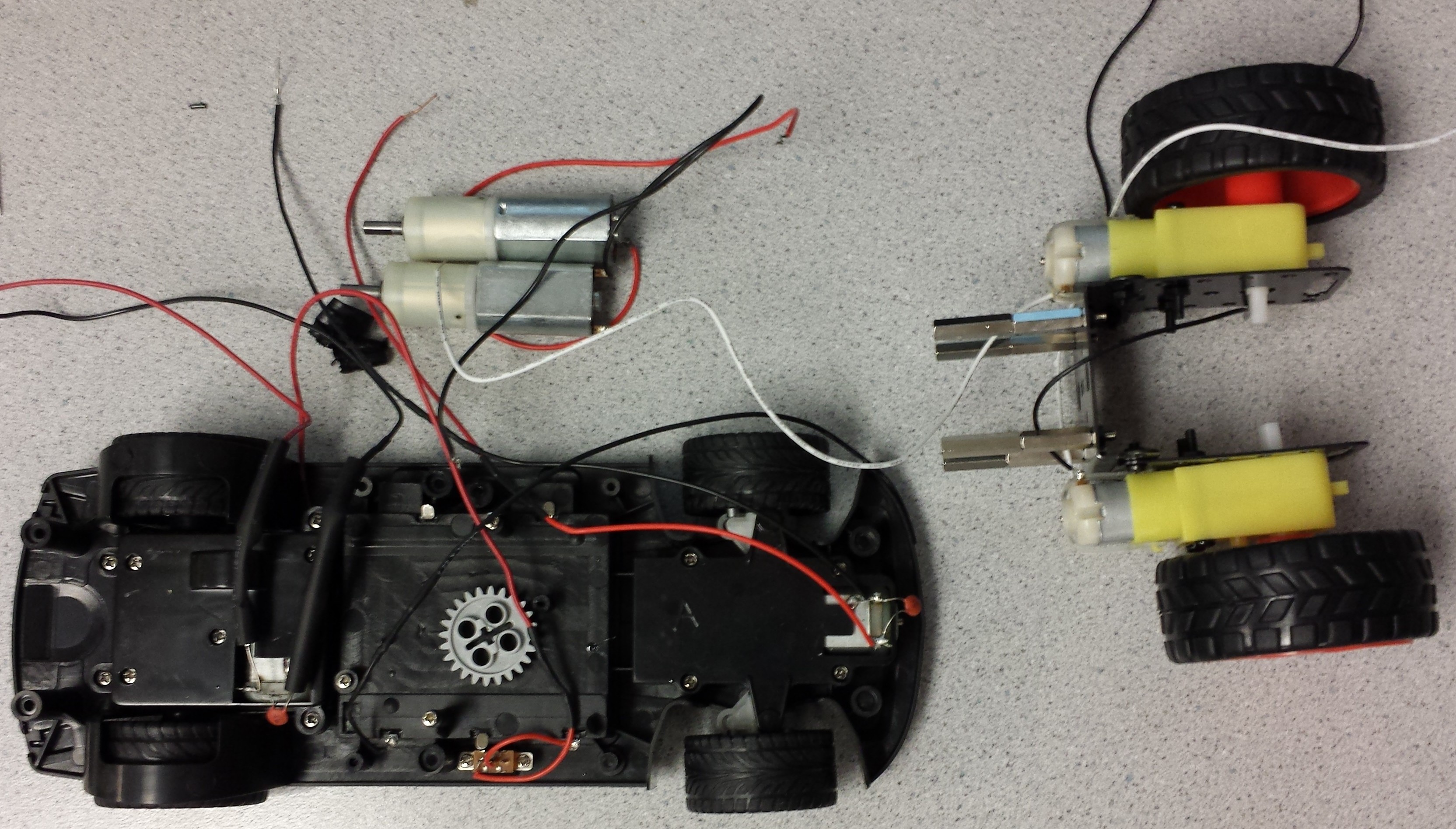
One major bottleneck in the capabilities of our robot was the motors. We salvaged both of the motors we used from toys. Figure ??? shows our initial findings and very early construction of the robot.
Software top
LSM9DS0 Library
The first piece of software developed for the balance bot was a library that used SPI to communicate with the LSM9DS0, the 9 axis Adafruit IMU. Using the published Adafruit library as our inspiration, which was designed for the Arduino, we created our own designed for the PIC32. The library handled the SPI read transactions, the SPI write transactions, and the value conversions necessary to configure the IMU and extract sensible acceleration and gyroscope data. Below is the interface, found in lsm9d0.h:
void lsm9ds0_init(unsigned int CS_G, unsigned int CS_XM);
void lsm9ds0_update();
char lsm9ds0_whoami_g();
char lsm9ds0_whoami_xm();
float get_accel_x();
float get_accel_y();
float get_accel_z();
float get_gyro_x();
float get_gyro_y();
float get_gyro_z();
lsm9ds0_init takes in the pins that should be used as the chip select for the gyroscope and accelerometer chip respectively, configures the appropriate pins on the PIC and configures both the gyroscope and accelerometer chips by writing to appropriate registers using spi write commands. The gyroscope is configured in normal mode; see the LSM9DS0 datasheet for details. The accelerometer is configured for 100 Hz data generation on all three axes in 2G mode, though only one was used. Optionally, each of the chips can be configured with filters as specified in the datasheet.
lsm9ds0_update fetches data from all three gyroscope axes and all three accelerometer axes and stores it in the internal data structures of the library. Since the X, Y, and Z data for both chips are stored in sequential registers, only two SPI read transactions are made, both using the address auto-increment read mode. For both the gyroscope and accelerometer, the data for an axis is stored in two 8-bit registers so 12 registers must be read in total. This routine handles the appropriate bit packing used to convert the data into 32 bit floats used by the PIC32. This is called once per control loop tick to ensure the latest sensor data is used. get_accel_{x,y,z} and get_gyro_{x,y,z} return the converted data values as floats.
First the chip select line is asserted low to signal the start of a transaction with the appropriate chip (passed in as an argument). Since the first step is to send a read to the peripheral using the SPI TX buffer, we wait until the TX buffer is not full. As dictated in the LSM9DS0 datasheet, a multiple register read command is initiated by a sending a byte that contains the starting address as its 6 least significant bits and 1 in the 2 most significant bits. We then flush the read buffer using ReadSPI2 and execute the correct number of SPI reads using getcSPI2, which returns a byte from the SPI read buffer that is stored in our library. After the transaction is done, we assert the chip select line high to signal the end.
Similar to the read transaction, the write transaction begins with asserting the chip select low, and ends with asserting it high. To write a value into a register on one of the chips on the LSM9DS0, we first send the address, followed by the value. Reads after each byte written are mandatory.
Pitch Estimation
To estimate the angle of the balance bot from the vertical we used three pieces of data from the LSM9DS0 library: the angular velocity along the x direction, the acceleration along the y direction, and the acceleration along the z direction. Linear accelerations were ignored; the accelerometer was used as a tilt sensor.
Our filter design is inspired by the Kalman filter, but avoids all of the complicated covariance calculations. The Kalman filter averages a prediction estimate with a measurement estimate and optimally picks the weight of each. The measurement vector contains three entries: the angular velocity about the axis of rotation, and the two acceleration values. Our state vector is simply the angle and the angular velocity.
Our prediction estimate is calculated using the angular velocity:
The measurement estimate is calculated using the two acceleration values. Since we know that gravitational acceleration always points downward, our angle can be computed as:
To avoid expensive trigonometric computations, and since our region of operation is very close to zero, we linearize the above about 0:
Our filtered pitch estimate is then computed as follows:
The constant K, which ranges from 0 to 1 is used to choose the amount of preference the filter has for the gyroscope estimate versus the accelerometer estimate. We strived to use a value of K close to 1 to favor the gyroscope, which is smoother. The accelerometer reading is still essential, as without it the filter has no absolute bearing and drifts. See the results section for more details.
In order to account for a placement of the LSM9DS0 that is not perfectly flat, a calibratable constant is added to the accelerometer estimate:
The pitch offset, which is a median of two seconds worth of filtered pitch readings, is computed on start as well as on command by the pressing of a button attached to the PIC. The implicit assumption is that the operator will initiate a calibration when the PIC is close to balanced. The median is taken to avoid a noisy reading.
The filter routine implemented in run_sensor_filter implements the above equations and is invoked once per tick of the PID controller.
PID Controller
Our PID controller uses the filtered pitch reading as input and outputs the PWM (bidirectionally) to the motors. A PID loop’s output is traditionally computed as follows:
We want the balance bot to remain upright, so our desired pitch is 0 and thus our error function is the negation of the pitch reading. To avoid numerical errors, we take the derivative of the error function to be the raw gyroscope reading in the axis of rotation. This is valid, since the derivative of our angle is the angular velocity:
Our integration is performed Riemann style as follows:
The output of the PID loop is clamped to the maximum duty cycle possible. If the output is negative, the direction bits are appropriately set to the H Bridges that control the motors.
PWM signals are created using the PIC32 peripheral PWM functionality, initialized as follows:
OpenTimer3(T3_ON | T3_SOURCE_INT | T3_PS_1_64, GENERATE_PERIOD);
OpenOC1(OC_ON | OC_TIMER3_SRC | OC_PWM_FAULT_PIN_DISABLE, 0, 0);
PPSOutput(1, RPA0, OC1);
and a given PWM is asserted using SetDCOC1PWM.
The PID loop is implemented in protothread_pid in balance_driver.c and only runs when the measured angle is in [-20, 20] for easy turn off.
Display Thread
In developing, we used a TFT to display information about PID and sensor values. This is instrumental in debugging and operational diagnostics. However, the TFT display is not an integral part of the actual finished product.Serial Communication
We used a UART serial communication between the PIC and our lab computer in order to obtain data from the robot while it was balancing. The serial transactions are kicked off in a dedicated protothread to avoid locking up the control loop. This ensure high fidelity data for debugging and analysis.
Outputted over serial are the filtered pitch reading, the gyroscope pitch prediction, the accelerometer pitch prediction, the raw measurement vector consisting of one angular velocity and two linear accelerations, and the PWM duty cycle sent to the motors.
Results top
We achieve sustained balance for up to minutes at a time. The balance bot can recover from small gentle nudges by the operator. Precise tuning is required to achieve balance and limitations arise from the weakness of our motors. Nevertheless we are very satisfied with what we have achieved using the parts available.Pitch Estimation
Our estimation filter performed adequately well for the task at hand. We settled on a filter constant value of K = 0.9, which provides a smooth enough pitch reading without increasing susceptibility to gyroscope integration drift.
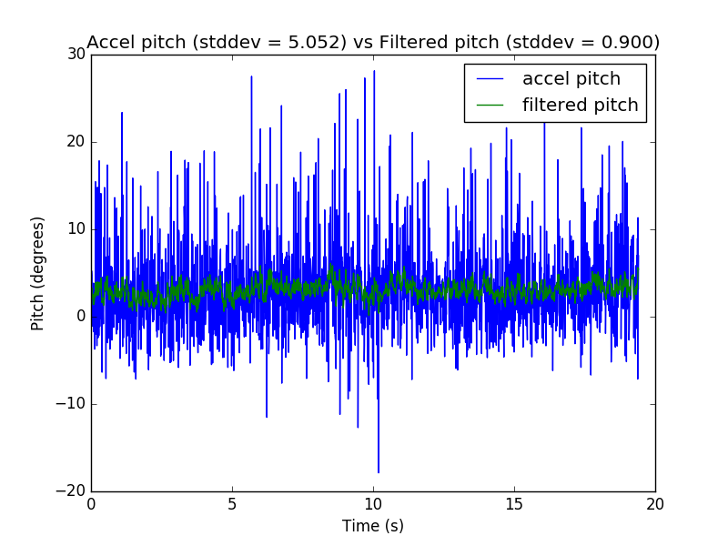
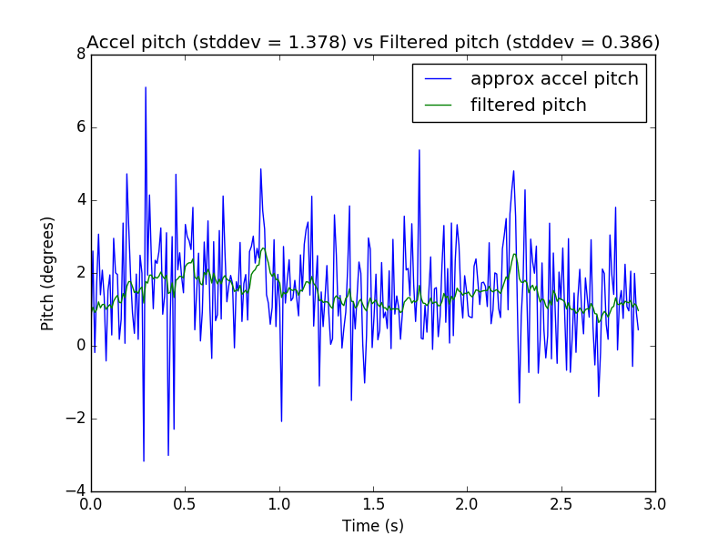
Plot 1 - A period of 20 seconds of balance bot balancing; note the relative smoothness of the filtered pitch reading to the acceleration pitch estimate.
Plot 1 shows that our filter reduces the standard deviation of the pitch estimate by a factor of 5 over the naive accelerometer tilt sensor during balancing. Plot 2 shows the same characteristics while holding the balance bot by hand, where we see a reduction in standard deviation by a factor of about 3.5.
These plots also show that while balancing, our controller was not able to stabilize the bot to within the noise bounds of the sensor reading.
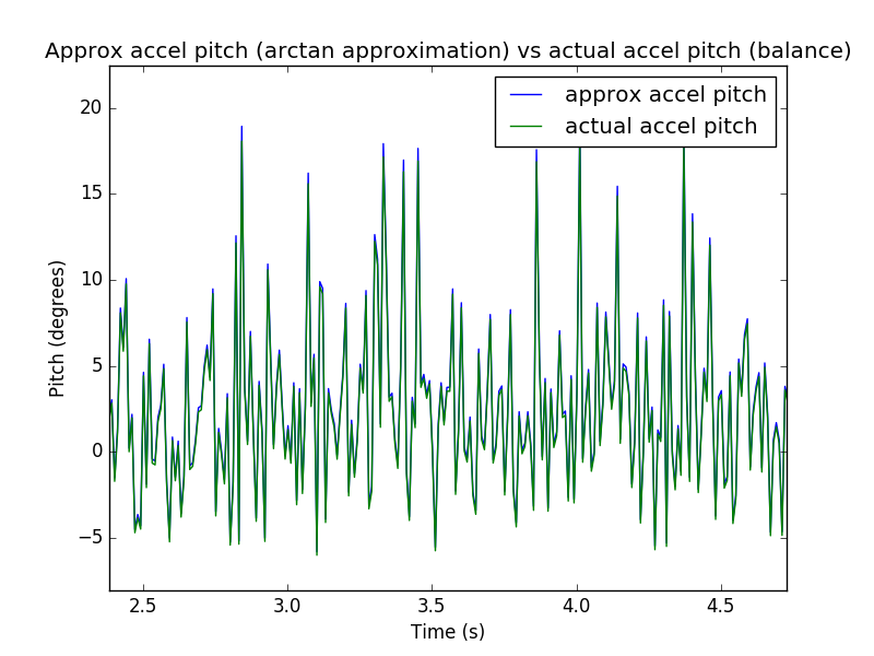
Our arctan approximation proved to be inconsequential:
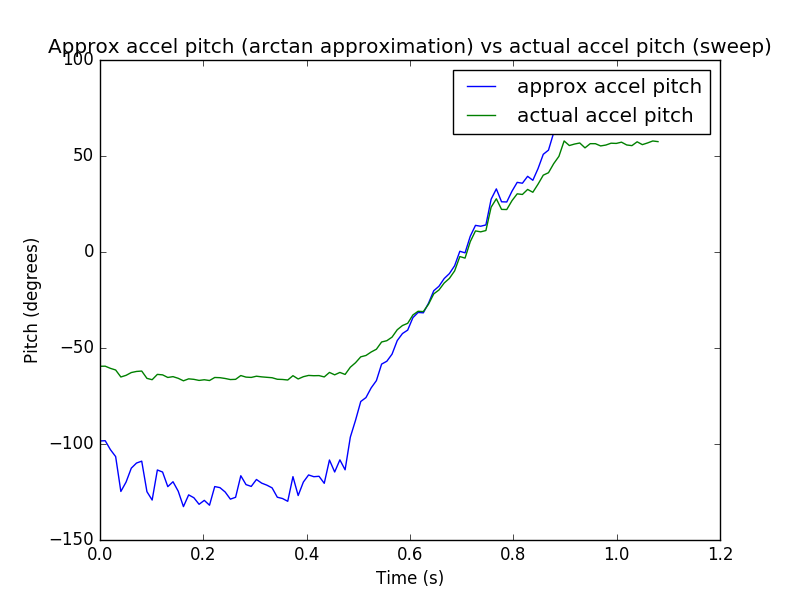
Plot 4 - Arctan approximation of pitch vs actual arctan during a 1 second sweep of the robot by hand.
Plots 3 and 4 show that the arctan linearization is very near exact close to zero and fails when the magnitude of the angle becomes greater. At such magnitudes however, the robot cannot physically recover so this is not critical. The actual arctan angle was computed using the raw acceleration data sent by the robot over serial.
Plot 5 shows the susceptibility of gyroscope integration to drift.

Plot 5 - Pure gyroscope estimation of pitch vs filtered pitch with K = 0.9 for a 20 second window during balancing
Without the constant correction of the ever noisy acceleration estimate, the pitch estimate would not be correct and the robot would fall after a short amount of time.
All analysis and plotting was done using Python and numpy in analyze.py.
Balance
Our robot was able to stay upright for up to several minutes at a time with the appropriate PID gains. The maximum recoverable tilt angle, as seen in Plot 7, is around 3 to 4 degrees.
Plot 6 shows how the balance bot responds and attempts to correct for tilts induced by hand. Note that only absolute value of the PWM duty cycle output was recorded during our data collection.
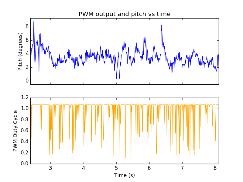
Plot 7 - PWM output and pitch vs time during 5 seconds of balancing. Note the actuator saturation. PID gains: P = 166, I = 75, D = 166
Plot 7 shows the balancing behavior of a particularly aggressive controller. Very little time is spent with the motors not at full power, a tell-tale sign of actuator saturation. With more powerful motors, it would be clearer if this controller is actually unstable. With our actuators, it becomes quite difficult to distinguish between aggressive controllers as they all essentially reduce to bang-bang controllers.
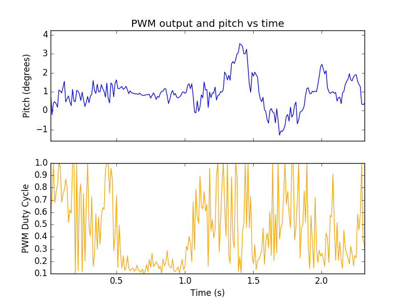
Plot 8 - PWM response during balancing of a less aggressive controller. The lull in pitch and PWM amplitude is due to operator intervention. PID gains: P = 116, I = 0, D = 140
Plot 8 shows the PWM characteristics of a less aggressive controller. At about 0.5 seconds the operator steps helped to balance the robot, resulting in very little PWM output. After 1 second, the robot resumed balancing. Note that very little actuator saturation is present here.
PID tuning was done using trial and error.
Other Considerations
Control loop rate had a considerable impact. At 100 Hz and above the robot balanced well. At around 50 Hz, the slower response time was noticeable. At 100 Hz, the robot could not balance for more than 0.5 seconds. Due to this constraint on control loop cycle time, it was detrimental to draw large amounts to the TFT display.
The period of the PWM signal was kept constant throughout the project. We used a 40 Mhz timer with the 64 prescalar and a generating period of 1000. This results in a PWM frequency of 625 Hz.
The balance bot does not cause any mechanical or electrical interference with any other projects or equipment. There is no human-interaction needed. The bot should take care of itself. Humans are merely needed to supply power, and tune the control system (and perhaps give a helping hand).
The balance bot comes equipped with a safety feature that turns off the motors after a tilt angle greater than 20 degrees is achieved.
Simulation
In order to validate our controller and learn more about the dynamics of the inverted pendulum problem, we created a Python simulation of the scenario.
Equations of Motion
We treat the system as two point masses, a point pendulum of mass m, and a cart of mass M. Applying Newton’s law we have:
Simplifying one of the equations of motion:
where a is the linear acceleration of the car and alpha is the angular acceleration. Performing a torque balance yields the second equation of motion:
See http://www.profjrwhite.com/system_dynamics/sdyn/s7/s7invp1/s7invp1.html for more details.
The equations are rearranged in the simulator as follows:
Those accelerations are integrated to compute the linear velocities, and angular velocities, which are then integrated to compute the linear position and angle of the balance bot.
Control
Any Python based controller can be used into the simulator. The control is interpreted as a force applied to the base of the balance bot. All of the testing done in the simulator used a basic PID controller.
Features
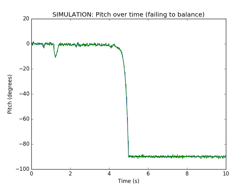
We strived to make the simulation as realistic as possible. Gaussian noise is added to the sensor reading fed into the controller to simulate the noise from the LSM9DS0. The maximum possible force available is capped to simulate maximum speed of the balance bot’s wheels. In addition, there is linear drag applied to the cart.
Visualization
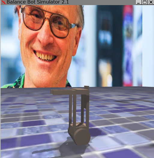
The visualization was done using a custom 3D engine written by one of our team members. The 3D model of the balance bot was created by our team using Google Sketchup.
Data
Below is pitch data over the time as the simulated balance bot attempts to balance:
Conclusions top
What Didn't Work
Our original design imagined a monowheel design for the self balancing robot. We quickly iterated into a dual wheeled design due to components immediately available at the time, specifically the DC motors and metal chassis. Professor Andy Ruina from the MAE department, who is quite familiar with the inverted pendulum problem, advised against the monowheel, and to instead that we focus on the more interesting control problem of self-balancing with a simpler two wheel design.
We attempted various “hacks” in the PID loop in attempts to improve control. None of them provided any discernible benefit. One of the more promising ones was a quadratic error term. This was motivated by the observation that the robot was quite aggressive near an angle of zero degrees but failed to compensate strongly enough at bigger angles.
The effect of these changes were hard to notice, likely due to actuator saturation. For many of our trials, the PWM output was saturated for most of the time.
Future Improvements
Our robot was built with a strategy based around rapid iteration. In retrospect, careful analysis of the mechanical dynamics would have likely determined the required motor characteristics and control algorithm gains. Instead, we spent our time searching for the optimal tuning in a massive space that is best explored using methodical analysis. In the end, the biggest limitation to our robot’s performance was the hardware, specifically the motors. The best strategy is to order a range of hardware types for the required components to find the ones that work best.
We have many ideas for future improvements over our current implementation. One opportunity is to incorporate a remote controller to allow for active desired pitch setting. This would allow the human user to drive the robot along its axis of motion. Another vision is improve the motors to a point at which they would be able to drive the balance bot up and down slowed surfaces. Lastly, we can envision creating a cargo platform for the balance bot to carry heavy items.
Intellectual Property
In its implementation, our final design correctly adhered to both the SPI and UART standards. Our source code leverages the plib.c libraries provided by the ECE 4760 course staff. Although we did not directly use any code from the public domain, our SPI controller was inspired by an existing driver for the Arduino microcontroller. Our design, although inspired by existing technologies, did not require reverse engineering of any existing product.
Ethical Considerations
Our project in its entirety, including design, development, and testing, has closely adhered to the IEEE Code of Ethics. All team members have accepted the responsibility of mitigating danger to our persons, others, and the environment in all phases of development. We have no conflicts of interest. We have accepted no bribes in developing our project. All presented data is, to the best of our knowledge, without manipulation and honest in its representation. We have have not expressed discrimination in any form based on gender, race, sex, religion, or otherwise to any member of involved party while developing this robot. We have also taken all possible and suggested precautions when working on our project. This includes proper grounding of components, eye protection when soldering, and testing for shorts before applying power, among others. Finally we have sought constructive criticism of our work at all stages of development, as well as encouraged our peers to adhere to these vary same code of ethics we have followed.
Legal Considerations
We do not believe our project infringes on any domestic or international laws or regulations. We do not plan to commercialize or sell any part of our project for profit.
Appendices top
A. Parts List and Costs
| Part | Source | Quantity | Unit Price | Total Price |
|---|---|---|---|---|
| Microstick II | Lab stock | 1 | $10 | $10 |
| Bread boards | Lab stock | 2 | $6 | $12 |
| DC Motor | Lab stock | 2 | $1.95 | $3.90 |
| L293D H bridge | Adafruit | 1 | $2.95 | $2.95 |
| LSM9DS0 Accel/Gyro | Amazon | 1 | $24.95 | $24.95 |
| Chasis | Lab stock | 1 | $0 | $0 |
| PIC32 | Lab stock | 1 | $5 | $5 |
| Total Cost | $58.80 |
B. Source Code
Please contact us via E-Mail for the source code.
C. Division of Labor
Although some members of our team may have focused on some parts of the project over others, we have all worked closely toghether on most all aspects of the design, testing, and development of the project.
| Leo Mehr | Alex Spitzer | Einar Veizaga | All |
|---|---|---|---|
| Chasis construction and project management | Software control system | Hardware Design | General debugging |
| Media creation and software debugging | Simulator Development | Hardware development | Documentation and report |
References top
This section provides links to external reference documents, code, and websites used throughout the project.
Datasheets
References
Acknowledgements top
We would like to thank Bruce Land and the rest of the ECE 4760 staff for their tremendous support and advice during the design, development, and testing of our project.
