Blimp-F-O is a remote-controlled flying machine designed with a PIC32 microprocessor.
Introduction
Flying drones have a wide range of applications and are becoming more and more popular. With that in mind, we decided to construct a balloon copter capable of fluid navigation in any direction. At the same time, we wanted our design to be reliable and capable of carrying a substantial amount of weight so that we could extend the project in the future. Our current design provides enough thrust, power, and CPU idle time to comfortably include peripherals like temperature sensors, video cameras, and displays.
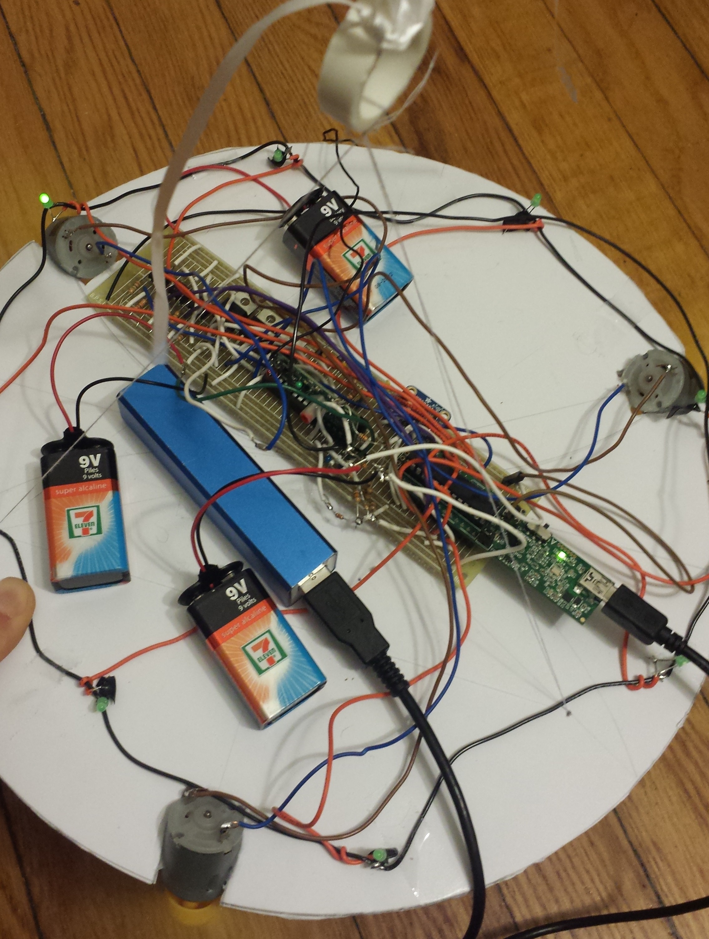
Blimp-F-O comprises a PIC32 microcontroller, an adafruit! accelerometer, three motors (with propellers), and an adafruit! 350 MHz transmitter/receiver pair. It is powered with three 9V batteries and a portable USB phone charger.
Here's a short video showcasing some of Blimp-F-O's features:
High Level Design
Functional Overview
Due to its unique and symmetrical design, Blimp-F-O is intuitive to control. To turn it on, four batteries are connected to clearly marked terminals, and the mini-USB cable is attached to the microprocessor. After a brief delay, the control system enters Hold Position mode, described later in this section. From here, we can calibrate the blimp to account for the loss of helium over time. Blimp-F-O can be calibrated either with the remote (for fine-grained precision) or by an on-board ballast system (for larger changes). Using the remote increases or decreases the duty cycle of the PWM signals to the three motors uniformly, while adding or removing ketchup packets - they were free - physically alters the weight, achieving the same goal.
Once calibrated, Blimp-F-O is ready for operation. A single green LED around the ring turns on to indicate the forward direction, and the user has complete control from there. A more in-depth video is available on the course's YouTube page.
Background Calculations
Designing a flying machine required a number of critical calculations before construction. In order to ensure that our blimp would be capable of flying, we decided to use helium-filled balloons to help offset the weight of the underlying components. Of course, we needed to calculate the bouyant force that a balloon would provide - these calculations are provided below:
Bouyant Force = V × g (ρ1 - ρ0)
where V represents the volume of the balloon, g represents the acceleration of gravity, and ρ1 and ρ0 correspond to the densities of air and helium, respectively.
At Ithaca’s elevation - around 400 feet (courtesy of Wolfram Alpha), the density of air is 1.212 kg/m3. Using the density of helium gas at STP (0.1663 kg/m3) and the volume of our balloons (36” diameter corresponds to 0.443 m3) we calculated that we will be able to lift about 1.40 kg.
Our conservative envelope calculations for total weight of the frame and components are as follows: 3 × 10g (motors) + 2g (accelerometer) + 3 × 3g (propellers) + 500g (batteries) + 10g ( receiver) + 20g (microcontroller) + 200g (foam frame) = 771 g. This is below the maximum theoretical lift calculated for our balloons to lift by a comfortable amount. To account for the additional lift, we employ a ballast system using an orange climbing bag full of ketchup packets.
Tradeoffs and Standards
Naturally, there are several tradeoffs demonstrated in our design. The power and size of the propellers, for instance, come at the cost of additional weight. Similarly, the number and size of our batteries, which determine the lifetime of flight of Blimp-F-O, could severly alter the weight and therefore require additional helium balloons.
Aside from typical engineering standards, our project does not require any additional standards. Ethically, we used and tested all of our components safely, and we made sure to adhere to FCC regulations, confirming that the used transmitter and receiver operate on legal frequencies (315 MHz).
Modes of Operation
Blimp-F-O operates through a finite state machine, which is updated every 30 milliseconds. In total, there are 9 states, which are described below. The driver can transition between these states by pressing commands on a 4-button remote control. The various commands are depicted here:
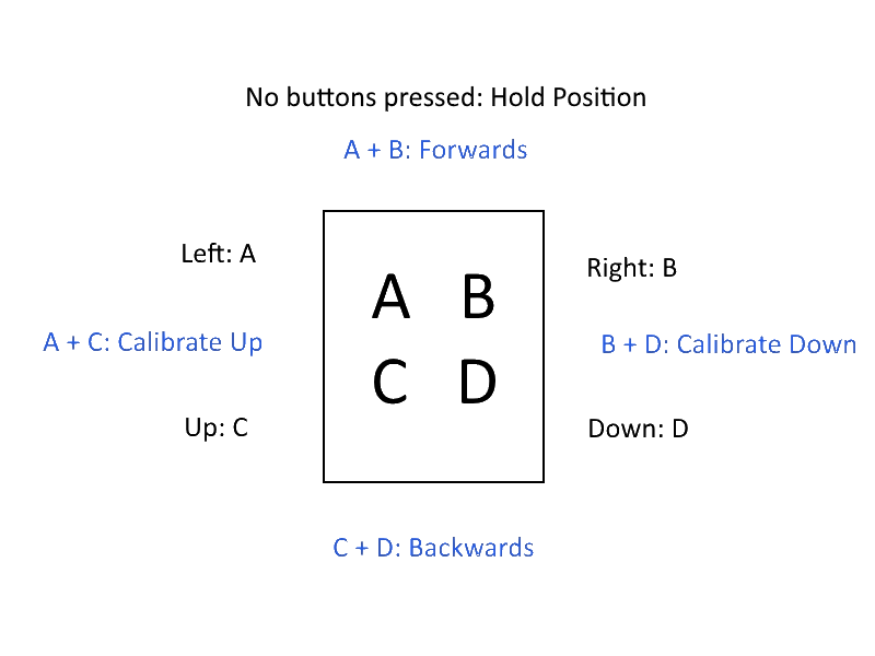
Hold Position: The default state, which uses data from the accelerometer to adjust motors individually. If the blimp begins to tip, the appropriate motors are adjusted to provide a restoring torque. In this state, the motors should provide just enough force to keep the blimp at a steady height, which turns out to be about 50% strength.
Forwards: The blimp proceeds in the direction of the lit LED. This direction starts at 0 degrees (i.e. pointing towards motor 1) and can be controlled through other states. Interestingly, the geometry of our design enables us to travel forwards at the same speed, regardless of which direction is forwards.
Backwards: The blimp moves in the opposite direction of the lit LED. Similarly, we can travel backwards at a constant speed for any direction.
Right: The angle inside the control system is adjusted to the right. Over time, this will cycle (clockwise) through the outer LEDs indicating that the direction of the blimp is changing.
Left: The control system angle is adjusted to the left. The outer LEDs will cycle counter-clockwise.
Up: The blimp turns on all motors to full strength to increase elevation. In this state, the blimp continues to right itself if one side begins to drop.
Down: The blimp turns off all motors, causing it to lose altitude. The self-righting code is still enabled.
Calibrate Down: If the Hold Position state is calibrated incorrectly (and therefore causes the blimp to rise when it should be still), this state will adjust the baseline motor strength until the blimp remains at a constant altitude.
Calibrate Up: If the Hold Position state is calibrated incorrectly (and therefore causes the blimp to fall when it should be still), this state will adjust the baseline motor strength until the blimp remains at a constant altitude.
Hardware & Coding
Pinout
This project involved communication between several modules, which operated on different voltage levels. To illustrate, the microcontroller's pinout is portrayed below:
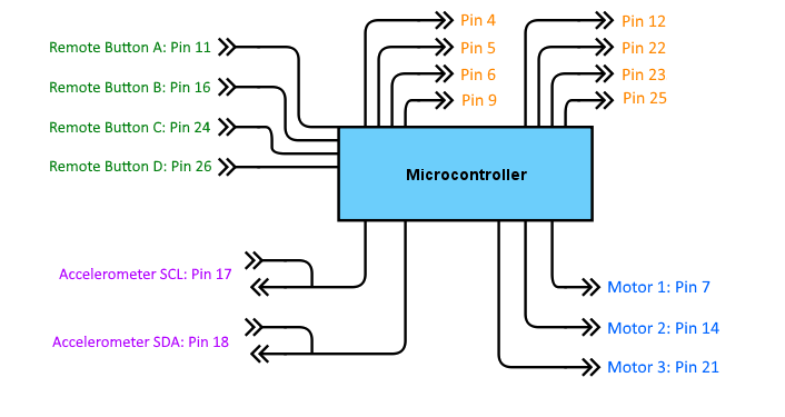
Each colored group in the diagram represents a category of connections:
• The green inputs come directly from the remote control module, and correspond to the four buttons - A, B, C, and D - described in the high-level design section.
• Similarly, the purple accelerometer connections correspond to the I2C interface between the microcontroller and the accelerometer. This interface is initiated in our main function, but the master microcontroller submits requests for acceleration information every 30 milliseconds.
• The yellow output pins connect to the eight green LEDs arranged in a circle around Blimp-F-O. These are used to tell the driver which direction is currently forward.
• Finally, the blue output pins consist of PWM signals to the three motors. These are set up using the PIC32's Output Compare modules 1, 2, and 3, all of which are sourced from timer T3.
Design
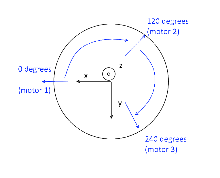
Because each component needed to use the same orientation data, we created a standardized coordinate system for the entire blimp, shown below. This coordinate system enables us to more easily code and calibrate the self-righting feature of our blimp. Whenever the accelerometer detects a spike in either x- or y-accelerations, an angle is calculated using an inverse tangent function which corresponds to the part of the blimp that is tipping down the most. From here, we simply use cosine and scaling functions to calculate the duty cycle for each PWM output.
As mentioned before, the PWM outputs themselves make use of the Output Compare modules. A timer, T3, counts to 40,000 counts repeatedly, signaling the start and end of a PWM cycle. Since our processor runs at 40 MHz, this corresponds to a frequency of 1,000 Hz. To change the duty cycle dynamically, we can input values into the duty_cycle register which correspond to timer counts. As an example, if we set the duty_cycle register to 20,000, then our duty cycle would be one half. This is further explained in the Code section below.
Below is a full schematic of our circuit. All of the components of our design were connected together with a common ground with the exception of the motors, which were controlled through an optoisolator to isolate the unpredictable and potentially harmful motor feedback signals from the microcontroller. The circuit is divided into sections: the left half provides power and voltage dividers for the RF receiver, the top represents the ring of LEDs with a common ground, and the bottom right section represents the three propeller circuits. We determined that two 9V batteries could provide enough current to keep the blimp airborne for around ten minutes. (click for full resolution)
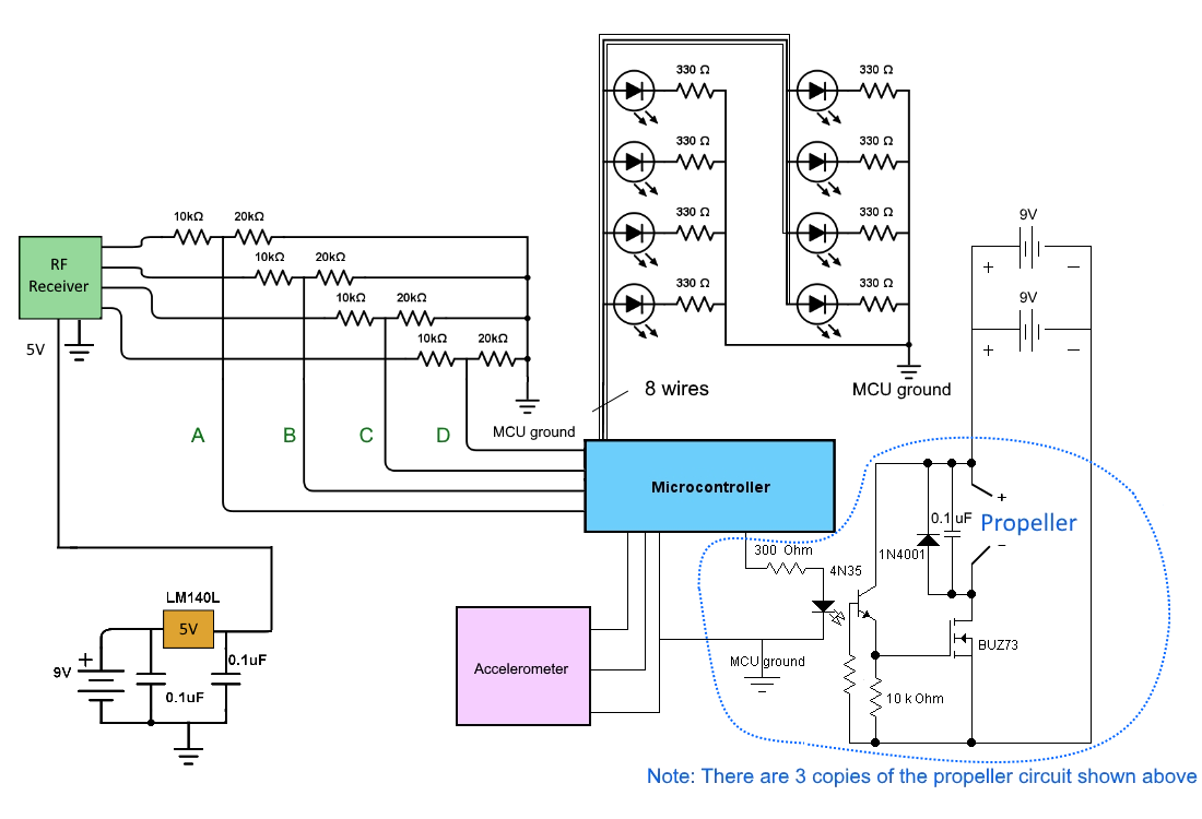
Many parts of the circuit were derived from our work in earlier labs. For instance, the propeller control circuits, which translate the PWM output of the microcontroller into a range of propeller speeds, were copied from Lab 4.
Furthermore, this circuit underwent several designs. We originally had connected an adafruit TFT display to help debug our design, although this occupied a large number of pins on our MCU. For this reason, we obtained a 1:8 decoder, which we could have used to operate all eight LEDs with only three control pins. After soldering the decoder (along with the eight resistors) we realized that without the TFT we would have enough pins to simply attach each LED to the microcontroller, which is what we ultimately implemented.
Code
All of our code for this project was done in C using the MPLAB X IDE. We used ProtoThreads to run multiple threads, which was especially useful for testing. At a high level, our code runs through a bunch of operations every 30 milliseconds. In order, these are:
1. Read data from the accelerometer
2. Read data from the RF receiver
3. Adjust the state of our FSM
4. Turn on the appropriate LED to indicate the forward direction
5. Based on the FSM state, calculate and set the motor duty cycles
We explain below some of the more interesting features of our code.
Accelerometer
Interfacing the MCU with the accelerometer turned out to be one of the most difficult challenges in this project. Even though the PIC32 supports I2C channels and has a few macros and functions to help establish a channel, there wasn't much documentation available online and we ended up doing a lot of programming by trial-and-error.
In our main() function, we initiate an I2C channel with a baud rate of 9600. To ensure that we have established communication with the accelerometer, we send the PIC32 master address and wait for a slave acknowledge. Then, while the code is running, we call a single getData() function which manages the communication and returns three eight-bit values corresponding to the x, y, and z accelerations. These values are then scaled from 0 to 1, keeping in mind that the value for the z direction in normal operation should read -g, the acceleration from gravity.
Motor Control
Part of the fun of this project involved the math behind the motor calculations. Since theta (the direction which is currently forwards and has a lit LED) could be any value between 0 and 2π, we needed a general-purpose technique to calculate the strengths of each motor. This task was complicated by the calibration states, which can drastically change the baseline "0 movement" motor speeds for all of the motors. Our solution was to implement the following equation for all three motors (n = 1, 2, 3):
Motorn duty_cycle = (upDown + (1 - upDown) × tipn)× calibrate
Using this equation, we have the power to change anything that we need to. Remember that a duty_cycle of 40,000 corresponds to a motor at full-power. UpDown manages the up and down commands (it is 1 in the up state and 0 in the down state), calibrate is (reasonably) set from 30,000 to 40,000 via the calibrate commands, and tip is a value from 0 to 1 which describes how much force each motor should provide. Looking at the equation, when upDown is 0 (i.e. the user directs the blimp to decrease altitude) the motors can still turn on if the blimp starts to tip, which is just what we desire.
The three tip values are usually calculated by a stay() function, which includes all the code necessary to self-balance. When a motor begins to tip, the tip value for that motor is increased until the blimp is level again. That being said, when we want to move either forwards or backwards we can use the tip values to move in the x-y plane. Given an angle between 0 and 2π, this is accomplished by setting the following values:
tip1 = cos(theta)
tip2 = cos(theta - 2π/3)
tip3 = cos(theta - 4π/3)
This is the genius of our coordinate system! Other than covering a few minor corner cases, this simple code perfectly sets the motors to move forward for any direction in the x-y plane.
Results
The Blimp-F-O design emphasizes high usability through the provided features. The accelerometer balancing provides ease of design on the frame layout as it removes the need to perfectly balance all components between the three points of support. Considering the number of asymmetrical components required for the design, this feature was possibily the only realistic method of maintaining a level frame during flight, and without doubt the most user friendly. Given the symmetrical nature of the design, a level frame is critical to maintaining control over flight direction.
Another provided feature is the ring of LEDs around the frame itself indicating the current set direction of travel. Since the the Blimp-F-O supports foward and backward motion in an infinite range of directions, the ring of LEDs provide the user with a method of determining the currently set axes of travel.
The third usability feature is the remote calibration of motor standstill power. In addition to ballast adjustment, the blimp supports dynamic adjustment of the baseline power level for maintaining level flight. Since the battery life affects power provided to the propellers, the exact PWM settings required to maintain a level flight change during operation. The dynamic calibration allows for a finer and more continuous adjustment than removing ballast allows.
Limitations of the final desgin that we observed and can be seen in the introduction video are chiefly the result of the balance between propeller power, battery life, and weight. Ideally, our blimp would support larger propellers and a longer battery life, however, the amount of lift we can provide is limited by the number of balloons we can attach to the frame. We calculated the maximum amount of weight supported by three 36" balloons is 1.40 kilograms. Although the propellers would increase the amount of weight supported, we wished to have room for adjustment with ballast and thus wanted to keep weight under this limit. This resulted in smaller motors and fewer batteries. As a result, the amount of weight imbalance that can be corrected by the accelerometer correction is limited by the propeller power. Additionally, the smaller propellers resulted in less robust controls, making it difficult to immediately change directions. Even though we separated our power supply into three parts for the RF receiver, the MCU, and the motor, we could only support 3 minutes of full power flight before noticing a decline in propeller power requiring a ballast adjustment.
Conclusion
Overall, the Blimp-F-O performed spectacularly and our team is pleased with the results. The features we set out to implement are as useful as anticipated and provide a fun remote blimping experience. If we were to create a second Blimp-F-O, however, there are additional or alternative features that we would strongly consider.
One issue we faced while testing the blimp was power stability resulting from a limited battery life. Although the total flight time provided by two 9 volt batteries was significant, the amount of lift provided by the propellers would decrease as a function of battery power. This required both control adjustments and ballast adjustments to maintain a level flight, disrupting the joy of simply flying the blimp. Therefore, we would consider a feature that allows the batteries to provide a stable amount of power for a longer period of time before dropping off. A simple method would be a regulator between the power supply and the motor; however, we were already operating under the maximum voltage supported by the propellers and a regulator would further decrease the range of control we had over the propellers. We were also unwilling to use larger batteries in an effort to keep design weight low.
Another feature we would like to implement is higher responsiveness to user input. This is not strictly any specific feature, as it is a function of the balance between propeller power and weight. Given the amount of ballast we used in our tests, we believe that we could have supported larger propellers strictly based on weight. However, we are unsure we would be able to provide the necessary power for larger motors. Even without larger propellers, there were several places we could have limited the weight of the design. For example, a more hollow frame would decrease weight at the cost of requiring suspension of the electrical components between the frame.
A final feature we would like to implement in a second design is rotational correction. Since the design features movement along any axis of the circular frame, we want to keep the set axis of movement constant for the user unless an input is given to change it. The blimp tends to unavoidably rotate during movement and alter this axis without any user input. Any small amount of wind or resistance can cause this rotation to start during flight. A rotational correction system to counter this movement would increase usability of the design by making steering simpler for the user.
Appendix
We provide the schematic of the design in the hardware and coding section.
Commented Code
Design cost
| Component | Cost |
|---|---|
| Simple RF M4 Receiver by Adafruit | 4.95 |
| DC3-12V High Torque Motor Propeller for Model Aircraft | 24.40 |
| MicroStick II | 10.00 |
| 5V voltage regulator | 2.00 |
| PIC32MX250F128B | 5.00 |
| 9V batteries | 9.99 |
| Balloons | 7.99 |
| Foam core | 3.99 |
| Battery clip | 3.99 |
| Keyfob 4-Button RF Remote Control by Adafruit | 6.95 |
| MMA8451QR1 | 7.95 |
| Total | 87.21 |
Task division
Jim
- Motor control
- Power control
- Solder board circuit
- Frame design
Brian
- I2C communication
- FSM implementation
- RF receiver communication
- Ring of LEDs
Joint
- Debugging
- Soldering
- Weight calibration