"A self-balancing two-wheeled robot utilizing an IMU and PID control for stability"
Project Sound Bite
A quick look at the range of mobile robots in existance reveals an enormous diversity in shape, form, and modes of mobility. However, one thing that most of them have in common is that they are passively balanced (i.e. their bodies are constantly in a state of stable equilibrium). While this is perfectly logical in most cases, there are certain applications, such as Segways and humanoid robots, that take advantage of an unstable-equilibrium, inverted pendulum design to enhance their capabilities. While their self-balancing mechanisms may increase the complexity of their design, the benefits, which include greater maneuverability and stability, outweigh the costs.
The two-wheeled design of the self-balancing Segway Personal Transporter significantly increases its maneuverability, because it reduces the turn radius to zero. The vehicle can rotate in place to instantly change its direction of motion and precisely navigate tight spaces that a three or four-wheeled robot cannot. Additionally, while a passively balanced, stable-equilibrium system may tip over the instant it is put off balance, an actively balancing, unstable-equilibrium system like the Segway can take actions to recover if its balance is temporarily disturbed. This stability-enhancing behavior directly mimics the natural behavior of a human that avoids a fall by taking a step in the direction of motion.
To demonstrate the benefits of such a design, we built an upright, self-balancing, two-wheeled robot utilizing an IMU and a PID feedback control loop to maintain stability. This report contains a thorough discussion of our project, including details about the mechanics, electronics, software, and everything else that went into designing, building, and testing our self-balancing robot.
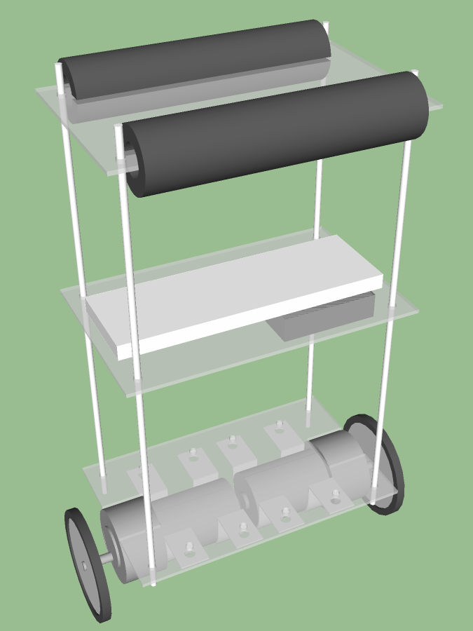
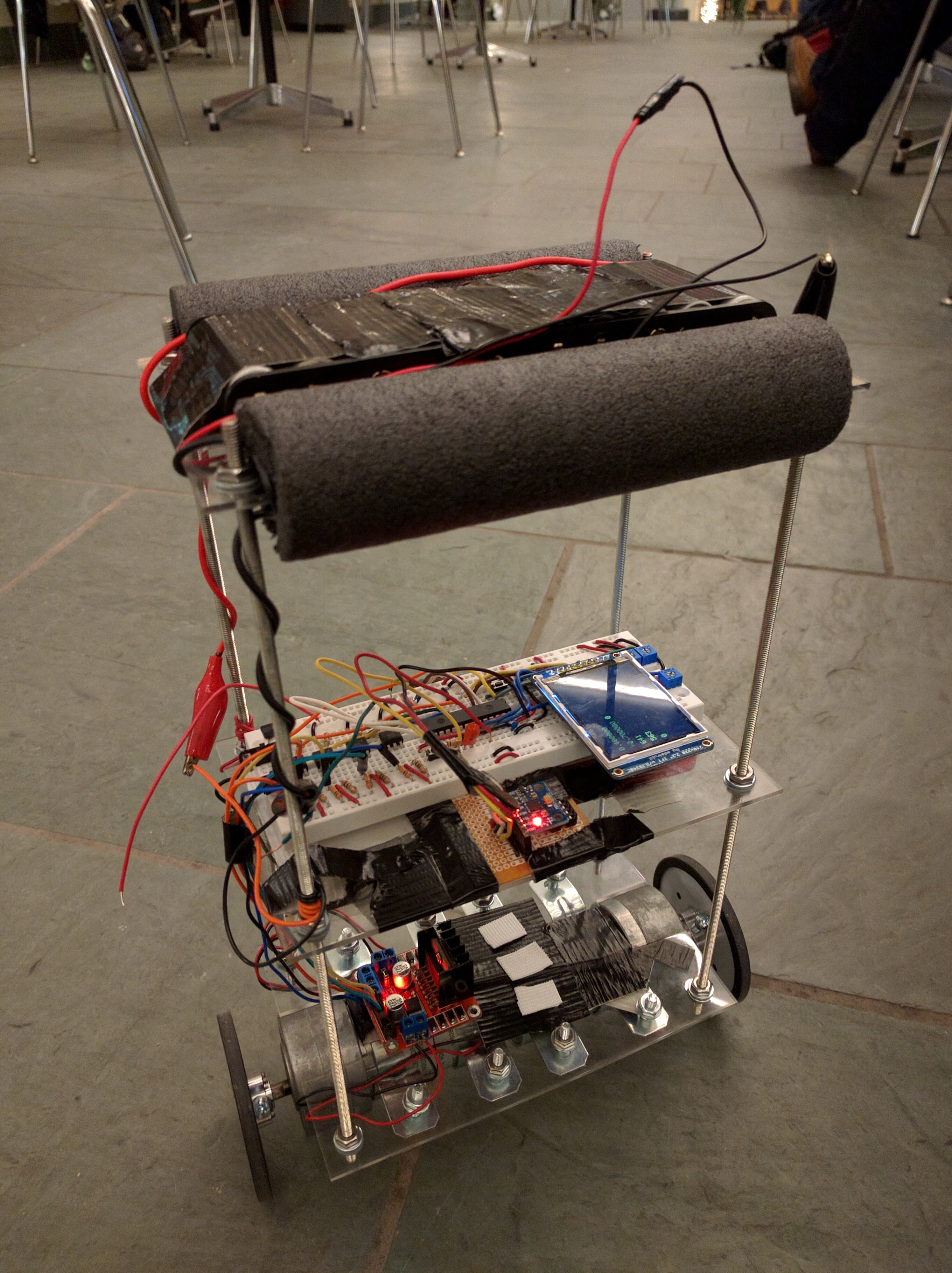
Figure 1: CAD model (left) and the final product (right)
Video: Our final product demo
High Level Design top
Rationale
Because of the previously stated advantages that come with a two-wheeled self-balancing design, a number of consumer products have recently gone mainstream that utilize a similar idea for purpose of convenient human transportation. Our goal with this project was to demonstrate the balancing mechanism used in these products in a compact, cost-effective prototype of a self-balancing robot. Given that this is our final project for the course ECE 4760 Microcontrollers at Cornell University, we also wanted to integrate a broad selection of of topics from the course material, including multithreading, pulse-width modulation, and feedback control among others.
Mathematical Background
Our self-balancing robot design is essentially an inverted pendulum, which is a pendulum with its center of mass above the pivot point. Balancing an inverted pendulum is a challenge, because it is inherently unstable. The slightest disturbance from equilibrium position results in a force away from equilibrium that further destablizes the system. Therefore, keeping balance at an unstable equilibrium requires precise, low-latency control to instantly correct any errors in tilt the instant they happen.
To deal with this problem, we employed a PID controller that uses tilt feedback to control the torque of the motors and keep the robot balanced. A PID controller continuously measures a process variable (the tilt of the robot) and calculates an error value (angle from the vertical), which is the deviation of the process variable from some desired, ideal value (0 degrees from the vertical). The controller attempts to minimize this error over time by continuously adjusting a control variable (motor torque) according to the following equation, where u(t) is the control variable, e(t) is the current error in the process variable, and Kp, Ki, and Kd are coefficients that must be tuned to achieve the desired behavior of the controller:
Equation 1: Fundamental equation for a PID controller
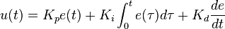
As seen from the equation the PID control variable depends on the current error (the proportional term), the rate of change of the error (the derivative term), and the long-term bias of the error (integral term), hence PID. This feedback loop, outlined in Figure 1 below, is the core of the robot's balancing behavior.
Figure 2: Diagram showing the steps involved in the feedback control loop of the balancing robot
While PID control is a proven technique and is widely used for a variety of different applications, it relies on accurate sensor measurements in order to properly do its job. Raw sensor data always contains a significant amount of noise that could be detrimental to the functionality of the robot if not handled properly. This noise comes from a variety of different sources, and effects different sensors in different ways. Therefore, we will exploit this fact to devise a sensor fusuion algorithm that builds on the strengths of each of the individual sensors to make up for the weaknesses of thge others.
While we can derive tilt by using just an accelerometer, the accelerometer measurements are prone to error in the short term, due to horizontal acceleration of the robot. So we average the measurements over time (low pass filter) to get a more accurate long-term reading, but also one that has significant latency. On the other hand, integrating gyroscope measurements is a very good predictor of tilt in the short term, but has significant drift in the long term. Because the gyroscope is good in the short term and the accelerometer is good in the long term, we average the two together in a weighted average in what is called a complementary filter:
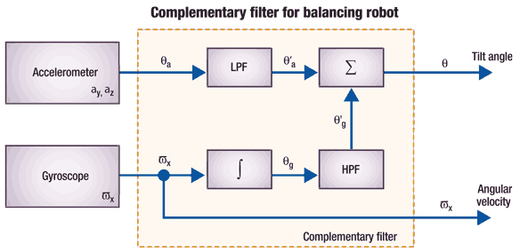
Figure 3: Diagram showing how the complementary filter fuses accelerometer and gysoscope data (source: mouser)
Each timestep, the complementary filter takes the angle calculated in the previous timestep, adds it to the integrated gyroscope readings for the timestep, and averages that with the angle derived from the accelerometer through a simple arctan computation on the acceleration vector components. The weights place more emphasis on the gyroscope-derived portion in order to reduce latency.
Design Overview
The electronics for this system can be divded into three main components - the microcontroller, the measurement subsystem, and the motor driver subsystem. For this project, we used a PIC 32 microcontroller unit. Multiple times a second, the microcontroller reads raw data from the measurement subsystem and sends PWM signals to the motor driver to be converted to mechanical motion. The measurement subsystem consists of an Invensense MPU 6050, a 6-DOF IMU that has an onboard three-axis accelerometer and a three-axis gyroscope. At a rate of 20Hz, the IMU measures the three-dimentional gravitational and rotational vectors and sends them to the MCU to be processed. When fresh IMU data is received, the MCU filters out sensor noise, and then fuses the data from the two sensors together to produce a single reading of tilt. Once the current tilt is known, the MCU calculates the error from the desired tilt, in this case the vertical, and then uses PID to control the PWM output to the motor driver subsystem. The motor driver subsystem consists of a Dual H-bridge DC motor driver connected to two 12V Merkle Korff DC gear motors. The circuit for the motors is separated from the circuit fro the microcontroller using 4N35 optoisolators. These isolators ensured that the microcontroller unit is unaffected by inevitable voltage spikes from the motors. The MCU and IMU are powered by three NiMH AA batteries in series for a total of 3.6 volts, and the motors, which require 12 volts, can be either powered by a wall-connected power supply, or 10 onboard NiMH AA batteries connected in series for a total of 12 volts. We added a 2.2" TFT LCD display unit to aid in debugging purposes, such as to display the current tilt, rotation rate, or the currently selected PID coefficients that can be tuned via onboard potentiometers. Figure 3 below shows a block diagram of electrical components of our design.
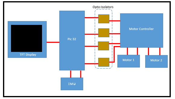
Figure 4: High-level block diagram of the robot hardware with TFT display for debugging
The mechanical design of the robot consists of three horizontal platforms made of acrylic glass, and held together by a rigid frame of four 12'' threaded rods and machine screw nuts. Each motor is securely connected to the lower platform via two semicircular brackets and machine screws. Before we began the assembly of the robot, we made a detailed CAD model of the design in SketchUp, seen in Figure 1 above. That helped us decide in advance what parts we needed to get and of what quantity, and also allowed us to verify that all of the parts fit perfectly together. When it was time to actually build the chassis, we used blueprints derived from the CAD model in order to laser cut the acrylic glass to the correct shapes we required.
Hardware/Software Tradeoffs
Our hardware design follows a minimalist approach primarily due to budget constraints. Ideally, we wanted to use a motor with enconders and high RPM. Encoders allow direct measurement of the speed of the robot, which is necessary to avoid motor speed saturation that may cause the robot to be unable to keep its balance. However, we ultimately settled and made do with 140 RPM motors with no encoders. That added some necessary complexity to our software implementation, but our robot was able to balance without any serious issues.
One major component of this project involves tuning the PID coefficients to achieve stability. To avoid hard-coding these values and re-programming the robot every time, we tied the values to three potentiometers, one for each PID coefficient. Without this feature, it would have been difficult to properly tune the PID coefficients. As another feature to aid in debugging, we added a push button that zeros the desired tilt angle whenever it is pressed, in order to enable calibration of the robot for uneven loads that may move the center of gravity off from the physical center of the robot.
Mechanical Design top
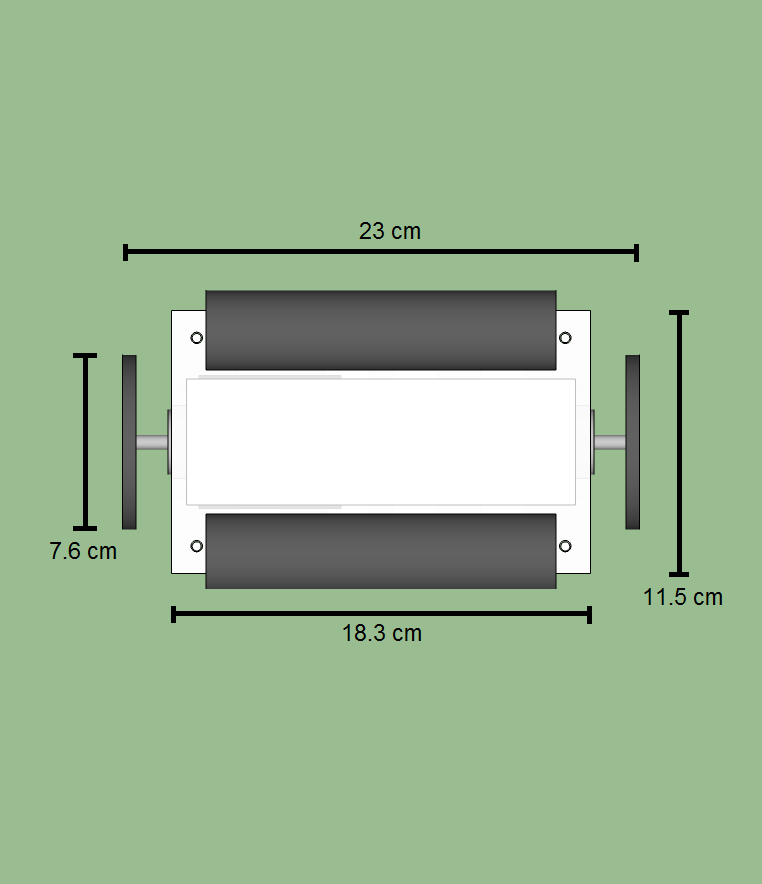
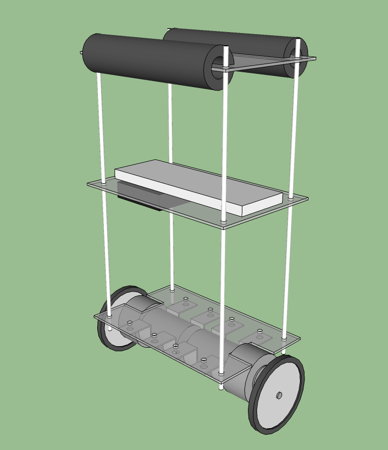

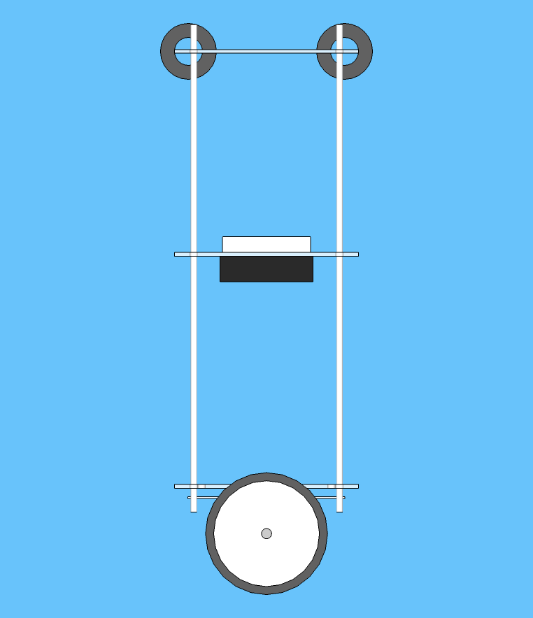
Figure 5: CAD drawing of robotic chassis in SketchUp, from four different views
Chassis
Our goal in designing the chassis was to build a rigid frame that is inexpensive, relativiely light, and sufficiently adjustible to meet our needs throughout the development of the project. To meet these requirements, we decided to go with a minimalist design composed of parts that can be found in an average department store, like Home Depot or Lowes. We settled on a sheet of acrylic glass for the three platforms, supported by four 12" threaded rods and connected by machine screw nuts and washers. The motors are secured beneath the lowest plaform using four semi-circular metal brackets and eight additional screws, nuts, and washers. We lined the top platform with foam pipe insulation, to cushion the robot against some inevitable falls. The precise list of parts and materials, as well as the CAD files themselves, can be found in Appendix C below.
We first designed a CAD model of the robotic chassis in SketchUp (Figure 5 above), and once we were happy with the design, we laser-cut the acrylic according to the CAD model. The Rapid Prototyping Lab in Rhodes Hall at Cornell University has a free laser cutting service that we utiilized for this project. Figure 6 below shows the blueprints for the laser cutter of the three platforms (the left one is the base to which the motors attach). No other parts needed to be cut or fabricated, so the rest of the construction was relatively straight forward, and involved mainly tightening nuts.
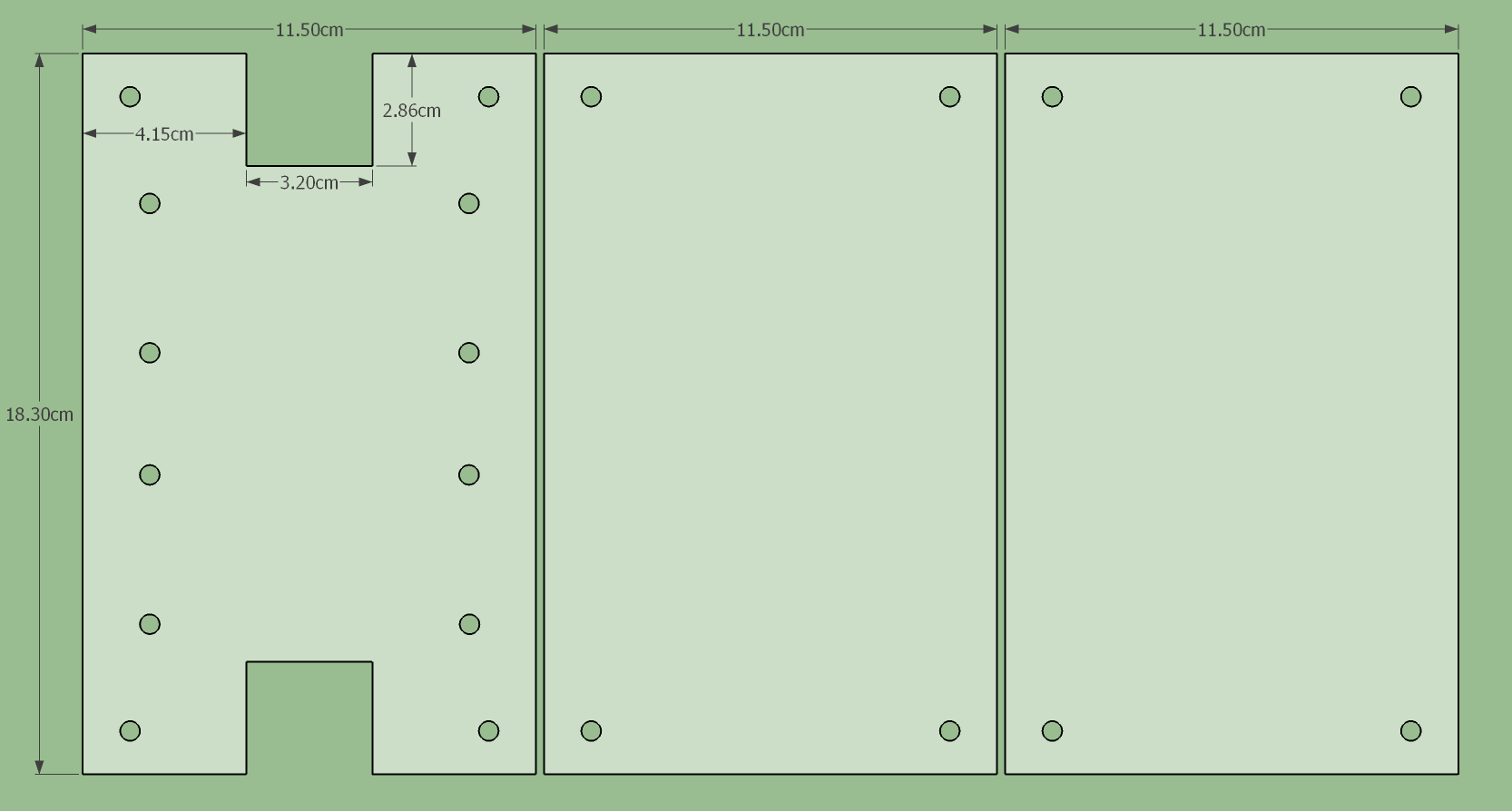
Figure 6: Template used for laser cutting the acrylic sheet for the chassis
Motors
One of the most critical and challenging decisions we had to make for this project was selecting the motors. There is a huge variety of motors available for ordering online, but the challenge was finding a set that fit our specific needs for the project. For the robot to properly balance, we knew that we needed motors with high torque and a sufficiently high RPM to allow us to connect the wheels directly to the motor shaft (to simplify the design). A high torque is necessary in order to avoid stalling, and a high enough RPM is required to prevent the motor speed from saturating during normal balancing behavior. Current consumption is also a factor, as we we wanted to be able to power the motors using on-board batteries, and not have to remain tied to a power outlet. As with everything else in this project, we were limited by budget constraints.
Given all of these requirements, we spent a significant amount of time comparing different options for motors before settling for two 12V Merkle Korff DC gear motors. These motors are rated at between 130 to 150 RPM, with 5.6 lb-in of torque, and requiring about 1.5 A of current at full load. We bought them off of Ebay for about $11 each.
The only problem with these motors was that they did not come with motor brackets, or any way to conveniently attach them to the robot. Because of this, we had to get creative with ways to securely attach them to the chassis and prevent them from sliding around. To solve this problem, we used four 1 1/4" EMT straps (Figure 7 below) from Home Depot, which happened to fit perfectly around the body of the motors, and had two holes that conveniently connected to the bottom platform of the robot with screws and nuts.
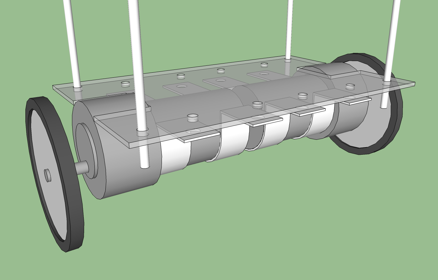

Figure 7: Closeups of the bottom of the robot highlighting the four EMT straps holding the motors in place (screws connecting straps to chassis not shown)
Wheels
The wheel diameter was chosen based on the RPM of the motor. We calculated that with 150 RPM, and a wheel diameter of 3", we could get a maximum speed of about 2 ft/s, which is about 0.6 m/s, which seemed like enough, given that we did not entend to drive it around at high speeds. We chose a set of 3" diameter wheels with rubber tires in order to increase the grip on smoother surfaces such as tile floor. We attached the wheels directly to the motor shafts using a set of wheel hubs that we ordered separately.
Hardware Design top
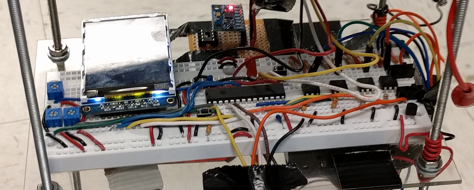
Figure 8: Breadboard with PIC32 (center front), optoisolators (right), TFT LCD (left), and IMU (center back)
PIC32 Microcontroller
The PIC32 microcontroller serves as the brain of the robot. It reads the sensor data, filters and fuses it together, runs the PID controller and controlls the operations of the motors and the LCD display. Unlike in previous labs where we used a Microstick II development board, we decided to set up the standalone PIC32 on our breadboard due to budget constraints. We used the Microchip PICKit 3 in-circuit debugger in order to program the PIC32 via USB from the MPLAB X IDE.
Invensense MPU-6050 IMU
In order for the robot to be able to keep its balance, it requires sensors that allow it to measure its tilt accurately and at a high measurment rate. For this, we chose the MPU-6050, an IMU that combines a 3-axis gyroscope and a 3-axis accelerometer with an integrated circuit. It has a digital interface and communicates with a host microprocessor via the I2C bus.

Figure 9: MPU-6050 IMU break out board that we used for this project
To get it to work, we utilized the I2C functionality built into the PIC32, and wrote a few device specific functions that read data from this IMU. Overall, the MPU-6050 is very easy to set up and use, but it is useful to note that it starts up in sleep mode by default, and does not make any measurements in this state. To get it running, simply clear the sleep mode bit from the second power register (see the register map), and the IMU will instantly begin to measure data and store it in its internal registers. To retrieve the measurements, simply read the registers corresponding to the data you care about. Each accelerometer and gyroscope measurement comes as an integer in a set of two bytes, an upper byte and a lower byte. Concatenate the two in order to get the full piece of data.
For this project, we only needed two axes of accelerometer data and one axis of gyroscope data. We read these three values once every 50ms, and ran them through the complementary filter described above to fuse them and derive an accurate and low-latency tilt measurement. This tilt measurment is what is fed into the PID controller to balance the robot.
In order to improve the stability of the robot, we took a few extra steps to calibrate the sensors and achieve more accurate measurements. First of all, when the robot is turned on, it should be lying on its side on a stable surface to allow it to calibrate its gyroscope. It does so by taking a large number of measurements while stable, averaging them, and subtracting the offset from any subsequent measurements. This makes sure that the robot does not have any bias in its gyroscope measurements, which would make it think it is rotating when it is actually not. Once that is done, the robot needs to be calibrated to zero its tilt. While it may seem logical to assume that zero tilt should be when the robot is vertical, we wanted it to work in the general case when the center of gravity might not always be at the center of the robot. Therefore, we added a push button that, when pushed, sets the current tilt as the "zero tilt" that the robot strives to achieve. That allows the robot to account for any sort of uneven load that it may need to carry.
4N35 OptoIsolators
With our experience using motor controllers, we knew it was necessary to isolate the microcontroller circuit from the motor circuit. When motors are powered on or changing directions, they can generate voltage spikes which often resets the microcontroller and halts the functioning of other systems. In order to mitigate this issue, we used a 4N35 optoisolator that properly separates the microcontroller and IMU circuit from the motors and motor driver circuit. The optoisolator receives its inputs from the microcontroller ports. When those ports are high, the optoisolator is high. This system uses four optoisolators: each motor uses two isolators, one for each wire. Since the wheels were not spinning at the same rate, we had to adjust the resistors connected to the input port of the isolator. For the fast spinning wheel, we used 300 Ohms. For the slow spinning wheels, we used 60 Ohms.
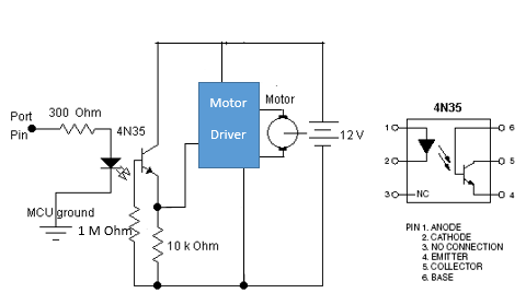
Figure 10: 4N35 OptoIsolator Setup with Motor Driver
Dual H-Bridge Motor Drivers
We used two motors that were connected to a dual H-bridge motor driver. We decided to buy this H-bridge device instead of building one because this device is convenient, reliable, and a more compact than what we could have built. The motor driver comes with a heat sink which was very important considering the large current draw of the motors, and the large amount of excess heat.

Figure 11: LN298N motor driver board with heat sink
Power
In order to power our robot, we needed a powere source that could supply 12V and sufficient current to power 2 motors, each of which can require as much as 1.5A at maximum load. Therefore, we started with a 12V 3A wall power adapter that we got from Ebay. The problem was that this power adapter seemed to shut down when the motors jittered or suddenly switched direction at maximum speed. This may have been due to current spike above 3A or voltage spikes eminating from the motors when they switch direction. Because of this, we decided to stop using that power adapter, and switch to a variable power supply in the lab, which can supply much higher current. This fixed our problem, and the motors never shut off again, so this is how we demoed our robot, as can be seen in the video above. We also considered running our robot off of 10 rechargeable NiMH AA batteries in series to produce 12V, but we were not able to test that prior to our demo.
Software Design top
I2C_helper.h
This is a header file we created with helper functions that enable interaction with the IMU over the I2C bus.
- i2c_write() writes data to a specific register in the slave IMU.
- i2c_read() reads back data from a specific register.
- readImuValues() is a helper function that reads back all three axes of both the gyroscope and accelerometer sensors.
- calibrateGyros() is a function that, when powered on and and the robot is lying still, takes 1000 masurements of the gyroscope to estimate its bias. This leads to a significant mprovement in the stability of the robot.
finalproject_main.c
This is the main file of our project. It contains a main thread, that initializes everything from the PWM to the ADC. When the main function completes, it spawns two threads that handle different tasks in the self-balancing robot's functionality. The more important one is the PID thread, which is the thread that manages the robot's self-balancing behavior. It first reads and parses the gyroscope and accelerometer values from the IMU over I2C. It then fuses the sensor data using the complementary filter described above to derive a single filtered tilt value for the robot. Subtracting that from the desired tilt (derived by calibrating to the robot's point of balance), this thread calculates the error. Then, it computes the three PID terms and sums them using the user-selected PID coefficients. Finally, it converts the PID control value to a PWM duty cycle, and sends that to the motors so that the robot balances. A second thread, the ADC thread adjusts the PID coefficient based on three potentiometers, thus giving the user control of these coefficients without having to reprogram the MCU.
Results top
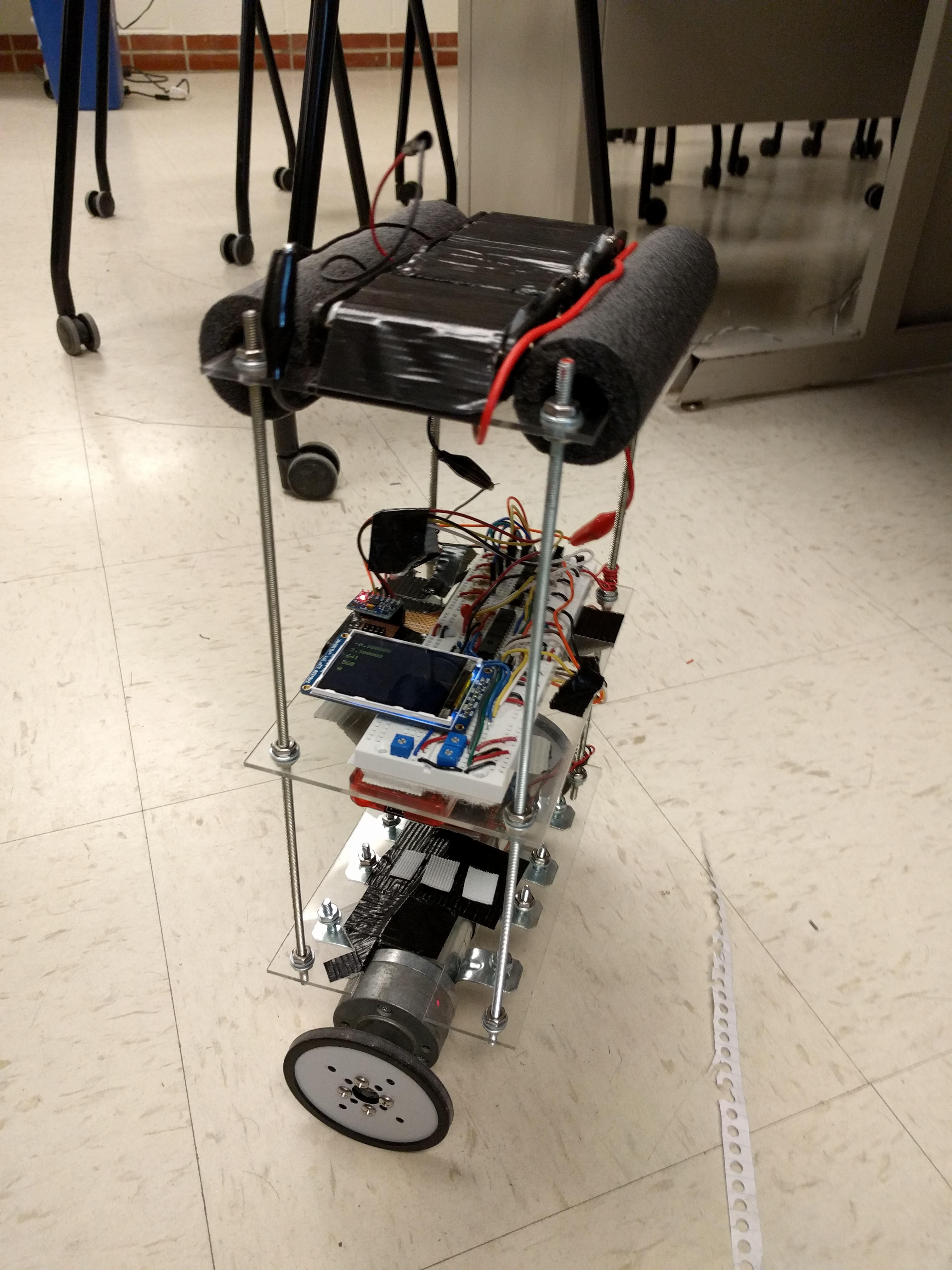
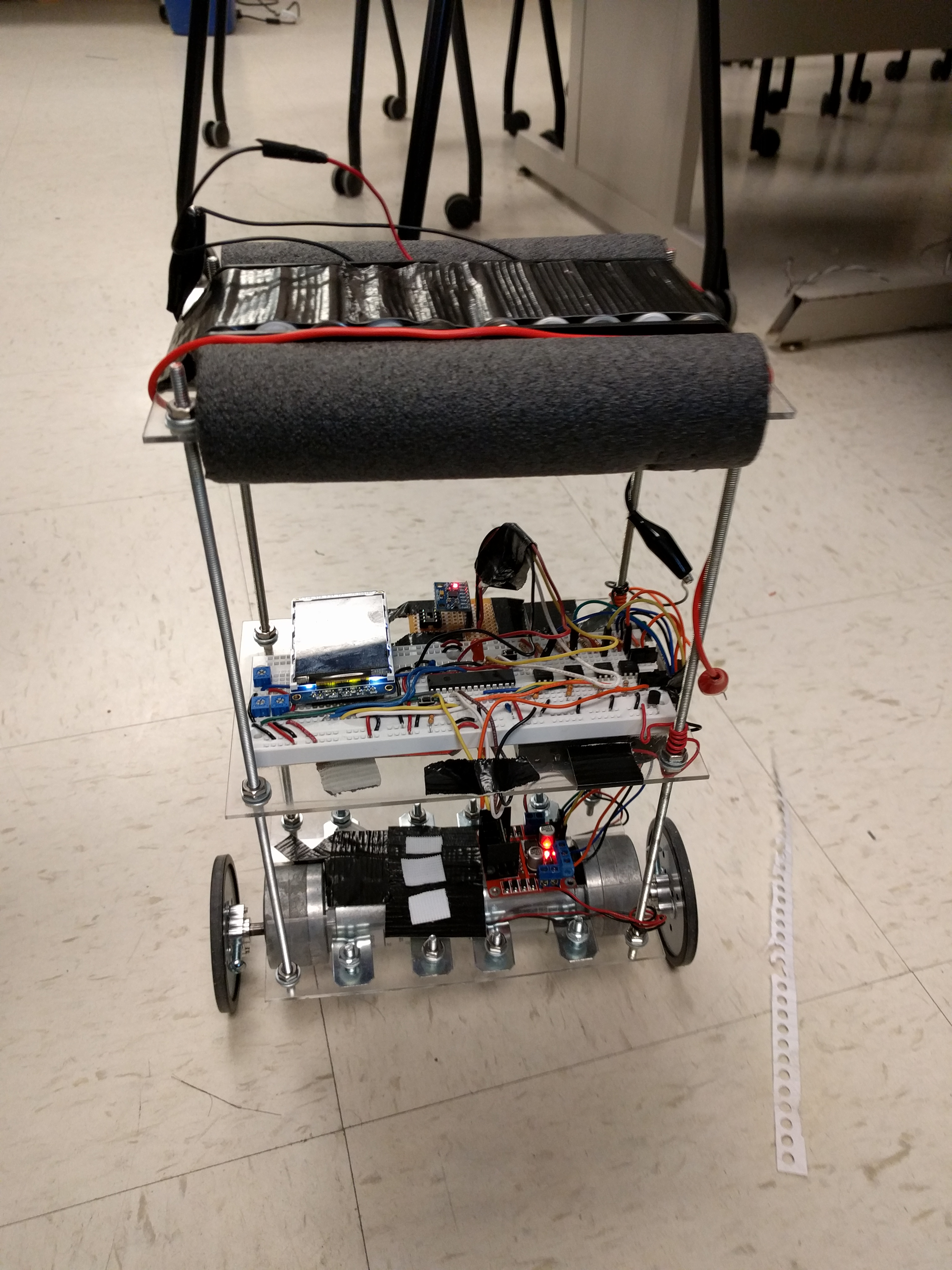
Figure 12: The robot balancing on its own, powered by NiMH batteries
Performance
Having manual control of the PID coefficients via the potentiometer turned out to be an enormous help, because it saved us an immeasureable amount of time while tuning the PID controller. By gradually tuning the PID coefficients, we were able to improve the stability of the system. It turns out that the robot is most stable for settings with very low D coefficients in PID, so our controller is effectively PI. To find the reason why this is the case will require a deeper analysis. After a lot of trial and error, we successfully got our robot to balance. If the gyroscope is properly calibrated, the tilt is zeroed, and the robot is placed gently in an upright position, it stays upright despite disturbances that would normally make it fall over. It is even able to carry a significant load and remain perfectly balanced:
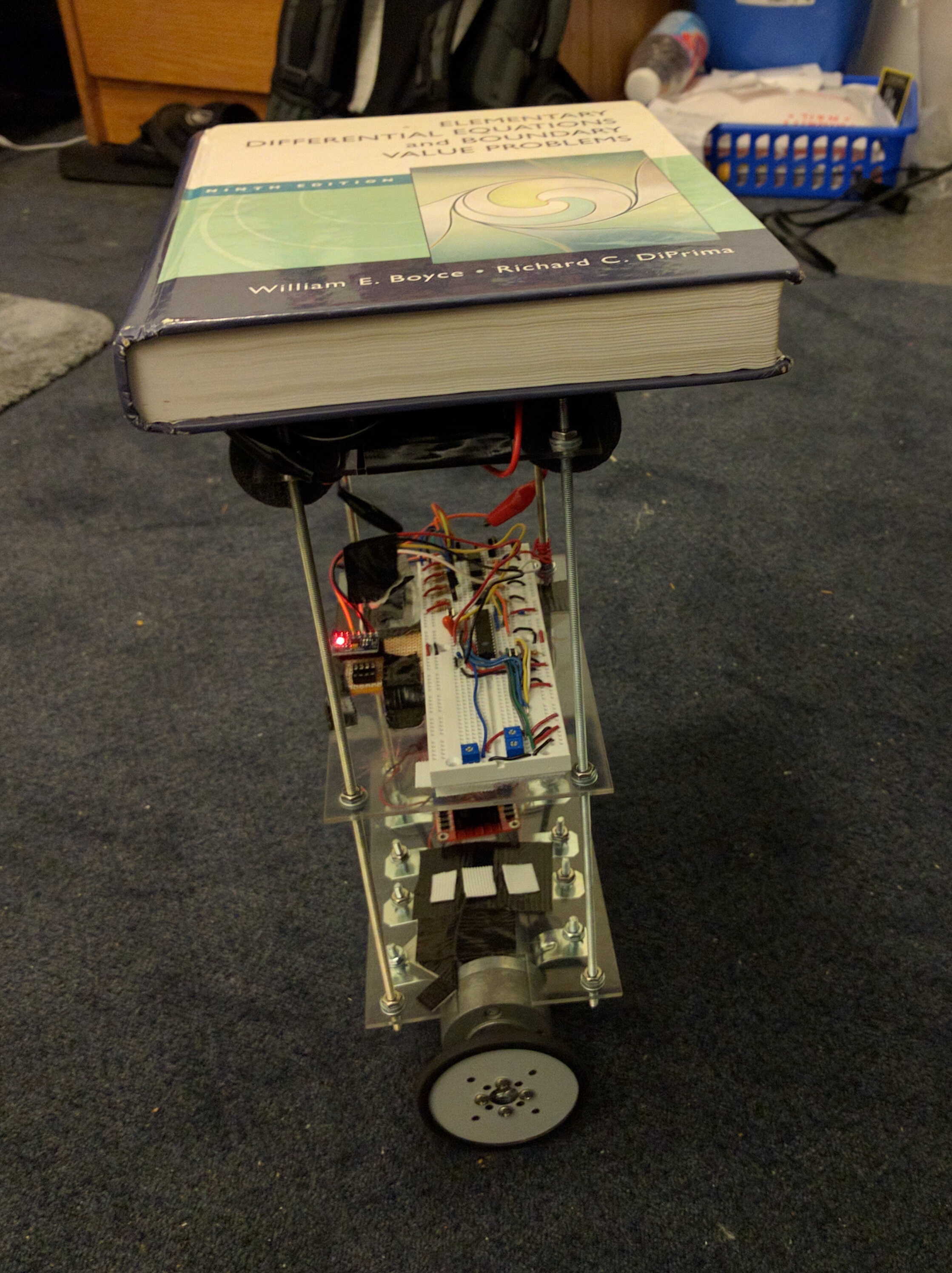
Figure 13: The robot balancing a substantial load
In our demo, the robot balanced for about 2 minutes before we turned it off, although it is capable of balancing for significantly longer periods. On a surfaces with high resistance, like carpets, the robot is able to balance more steadily than it does on hard surfaces like floors. We also noticed that raising the center of gravity improves the stability of the robot. That is the reason why we put the batteries (the heaviest part other than the motors) at the very top.
It also became very clear that the type of filturing used on the IMU data has an enormous effect on the stability of the robot. Due to incremental design, we initially had it such that the tilt measurement came from the accelerometer and the rotation rate came from the gyroscope. Both values were low-passed using an IIR filter. The significant latency and laggy response that occured as a result made it impossible for the robot to balance. But the complementary filter we then implemented solved all of the latency issues, and that is how we eventually got the robot to balance.
While the robot performed at least as well, if not better, than we expected, we did notice a few limitations that affected its performance. For example, regardless of how the PID coefficients are tuned, the robot always exhibits a minor wobble. We think this is due to the motors having a minimum PWM duty cycle threshold below which they do not move. That can possibly be compensated for in software to improve stability.
Second of all, while we supplied exactly the same power to both of the wheels simultaneously, one wheel tends to spin noticeably faster than the other at low speeds. This causes the robot to move in somewhat of an arc. The difference seems less noticeable at higher speeds. The robot still balances, so we did not spend too much time looking into this issue.
A third issue has to do with a design choice that we made. Due to budget limitations, we decided to not add motor encoders to our robot. Encoders are not inherently necessary for self-balancing, but they would would have allowed us to directly measure and control the speed of the robot. When testing our robot, we noticed that, for various reasons, it sometimes begins to accumulate speed. It remains balanced until it reaches a point where the motor speed saturates, the wheels cannot keep up with the body of the robot, and it falls over. Having faster motors could have helped, but the issue here is the lack of encoders. With encoders, we could have prevented the robot from approaching speeds that it cannot handle, and even controlled the robot such that it stayed in place rather than roaming around with no speed control.
Useability
We made a significant effort to increase the useability of this robot, both for ourselves to aid in debugging, and for the general user. The potentiometer PID coefficient control and the LCD display are two examples of ways to aid in debugging. By controlling the PID coefficients via potentiometer, we were able to make rapid iterations and test them immediately, without having to worry about reprogramming the robot. The LCD display, which showed us the coefficient values for PID, allowed us to record the ones that worked so that we could replicate them in the future.
In terms of general useability, we tried to make operating this robot as simple as possible. The user simply has to connect the robot to power, and then flip two switches to the ON position - one to power up the MCU and the other to power the motors. It is recommended that the robot lay down on a flat surface as the MCU is powered on, because that allows it to successfully complete the gyroscope calibration procedure before it begins operation. To calibrate the robot for an uneven load, simply press the tilt-zero button in order to zero the desired tilt to the current tilt of the robot, to compensate for uneven loads. While the LCD and potentiometers are very useful for development purposes, they can be completely removed from the product when given to an everyday user. Once the robot is tuned properly, there is simply no use for these parts anymore.
Safety
Because of the way the chassis is designed, if the robot falls over, the wheels are raised off the ground, and the robot becomes immobile until it is again placed upright. As an additional precaution, we could have also had an automatic motor shutoff past a certain tilt angle, but we never took the time to implement it. But regardless, this device is not a toy and has powerful motors and batteries. It should be used by kids only under adult supervision. Always use in a dry environment, and never expose the robot to water or moisture. Always remove the batteries before storing for extended periods of time.
Conclusion top
Evaluation
We came into this project expecting to build a two-wheeled robot that would balance itself with the help of an IMU. It took a good amount of work, and we encountered significant challenges, but we met our expectations and achieved our goal. After building the chassis, designing and testing the circuits, writing the software, and tuning the PID coefficients, we were able to sucessfully balance the robot on the two wheels, and even carry a load. But it is still not perfect - the few issues detailed above, including the minor wobble, the asymmetrical motor speeds, and the lack of encoders are small problems that can be fixed in a future update.
The key to completing this project was careful advance planning of every step we needed to make, and every material we need to buy. We spent what at first seemed like an excessive amount of time planning, but it all paid off in the end, because we were able to more effectively manage our time, and were more prepared for the problems we would encounter.
Future Improvements
- Fix the wobble by setting a minimum PWM duty cycle that is just below the threshold at which the motors begin to spin. That will get rid of the current deadspot in which the motors don't spin for a number of degrees.
- Fix the asymmentry in the motor speeds. That likely has to do with friction, so using machine oil to lubricate one or both of the motors might fix the problem.
- Add encoders to the robot to allow it to measure and control its speed. That will prevent it from approaching its maximum speed and falling over.
- Implement automatic tilt calibration so that the robot will always remain balanced even if its center of gravity is shifted, requiring no action by the user.
- Implement manual remote steering of the robot, commanding it to move forward, backward, and rotate clockwise or counter-clockwise.
- Add a light sensing system to the bottom of the robot and make it autonomously follow a dark path drawn on the ground.
Intellectual Property Considerations
We designed our robot completely from scratch, and as far as we know, we did not infringe upon any patents in the process. In order to enable multithreading, we used the Protothreads library developed by Adam Dunkels. According to his website, "protothreads are a extremely lightweight, stackless threads that provides a blocking context on top of an event-driven system, without the overhead of per-thread stacks". We also utilized some code adaqpted by the course staff from the Adafruit Arduino library in order to operate the LCD display.
Ethical Considerations
During the course of our ECE4760 final project, we strictly followed the IEEE Code of Ethics. We made decisions consistent with safety such that nobody was in danger of getting injured. We are honest and realistic in stating our claims according to data collected. We are accurate in listing our component cost to our best knowledge. We are willing to accept constructive feedback and incorporate it into our design. We strove to solve challenging problems by ourselves, and sought the help of the instructor and TAs for those we were not able to resolve. We did not hold any bias against anyone nor engaged in acts of discrimination based on race, religion, gender, disability, age, national origin, sexual orientation, and gender identity. We treated all of our peers with equal respect and offered help to our colleagues whenever possible. We give credit when using the code from any external sources to prevent any perceived conflicts of interests, and acknowledge all contributions made to the final project.
Legal Considerations
We think there is little patent opportunity for this project, because we have not really done anything novel and non-obvious. We did not have to sign any non-disclosure agreements for sample parts.
Appendices top
Appendix A: Source Files
- final_project.c (21 KB) // Our main project file
- i2c_helper.h (5 KB) // A header file that handles I2C communication with the IMU
- finalproject.zip (428 KB) // A zip of the entire MPLAB X project
- final_assembly.skp (393 KB) // A Sketchup CAD file of the robot mechanical assembly
- laser_cut_template.skp (130 KB) // A template for laser cutting the acrylic glass of the chassis
Appendix B: Schematics

Figure 14: Circuit schematic of hardware configuration
Appendix C: Cost
The total cost of our robot turned out to be $89.89, which is less than the maximum budget of $100. The details are shown in the parts list below:
| Part | Part Number | Cost | Quantity | Total Cost | Vendor |
|---|---|---|---|---|---|
| PIC32 | PIC32MX210F016B | $5.00 | 1 | $5.00 | |
| IMU | MPU6050 | $5.99 | 1 | $5.99 | ebay |
| TFT LCD Display | Model 1480 | $10.00 | 1 | $10.00 | |
| Motor | LYMC-62700-631 | $10.99 | 2 | $21.98 | ebay |
| EMT straps | $0.38 | 4 | $1.53 | Home Depot | |
| Wheel | $2.50 | 2 | $5.00 | Sparkfun | |
| Wheel hub/adapter | $4.99 | 2 | $9.98 | Servocity | |
| Breadboard | $6.00 | 1 | $6.00 | ||
| NiMH AA 1.2V battery | $0.88 | 3 | $2.64 | ebay | |
| 4-slot batter holder | $3.32 | 1 | $3.32 | ||
| 3.3V voltage regulator | MCP1727 | $0.00 | 1 | $0.00 | mouser |
| Optoisolator | 4N35 | $0.00 | 4 | $0.00 | |
| Dual H bridge DC motor drive controller | L298N | $5.28 | 1 | $5.28 | ebay |
| Polycarbonate sheet (11'' x 14'') | $4.54 | 1 | $4.54 | Home Depot | |
| Threaded rod | $0.98 | 4 | $3.92 | Home Depot | |
| Nuts | $0.08 | 32 | $2.71 | Home Depot | |
| Washers | $0.03 | 32 | $1.10 | Home Depot | |
| Foam Pipe Insulation | $0.10 | 1 | $0.10 | Home Depot | |
| Header socket/plug | $0.05 | 16 | $0.80 | ||
| PROJECT COST | $89.89 |
| Nadav Nehoran |
Sherry Zhao | Desmond Caulley |
|---|---|---|
| Chassis CAD design and construction | Report leader, wrote weekly upates | Circuit design - including interface between the IMU, optoisolator and PIC |
| Software implementation for I2C, data filtering, PID | Assisted in soldering and wiring | Soldered the circuit components and assembled the circuit on the chassis |
| Tuning of PID coefficients | Parts acquisition |
Software implementation for PWM |
References top
This section provides links to external reference documents, code, and websites used throughout the project.
Acknowledgements top
We would like to thank Professor Bruce Land and the course staff for all their fantastic help and advice throughout the semester and on this final project. We could not have done this without their support.
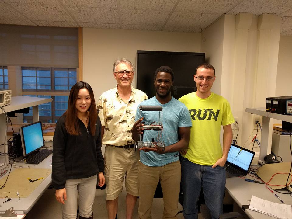
Figure 15: The team with Professor Bruce Land after the demo. From left to right: Sherry Zhao, Bruce Land, Desmond Caulley, and Nadav Nehoran