Results
Bluetooth
Using the HC-05 chip, bluetooth was used to control all aspects of the other circuits built for the project. Using a UART interface, bluetooth was very effective in controlling the amplifier. It was implemented using the protothreads DMA UART libraries. In the interest of time, we did not develop a front end for the bluetooth, however, using a bluetooth terminal on an Android device instead. Future work would involve building a fully functional front end to the amplifier.
Distortion
Our goal for the distortion portion of the circuit was to take our input signal through a raw distorted effect and output it through our class-D amplifier to our speakers. 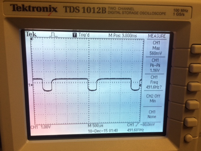 Figure 10: Distortion of Sinusoid on Oscilloscope Figure 10 presents the 'clipped' signal that is outputted from the distortion circuit. Our final distortion circuit was protoboarded and presented with the distortion effect being clearly heard through our speakers.
Tonestack
Our primary goal for the tonestack was to implement both analog potentiometers as well as digital potentiometers that could control the bass, mid, treble, and level functionalities of our guitar amplifier. The 100 kilaohm digital potentiometers wwould be controlled via smartphone through our HC-05 Bluetooth module and PIC32 microcontroller while the analog potentiometers would be controlled via physical tunable knobs on the guitar amplifier.
The analog portion of the tonestack was successfully wired on a breadboard and soldered onto a protoboard. The values chosen were 250 kilaohms for the bass/treble potentiometers and 100 kilaohms for the level/mid potentiometers. The effects themselves worked very well both on an oscilloscope as well as through our Class-D amplifier. Figures 16 and 18 present the bass and treble potentiometers tuned to their highest values, respectively cutting off the high and low frequencies from the signal input. Figures 22 and 24 present the bass and treble potentiometers tuned to their lower values, passing far more high and low frequencies from the signal input. Figure 17 presents the level potentiometer tuned to its highest value increasing the gain of the circuit. This capture can be compared to Figure 23 which presents the level potentiometer tuned to its lowest value (peak-to-peak value of the signal increases from 1 Volt to 9.6 Volts as level increases). Figure 19 presents the mid potentiometer tuned to its highest value amplifying the center frequency of our input signal. A small amount of 'clipping' is noticable due to our mid-potentiometer exceeding the dynamic range of our two 250 kilaohm bass/treble potentiometers. Figures 20 and 21 present the level and mid potentiometers tuned to their respective 'half-way' marks. Each potentiometer had a clear effect on the signal input when driven through the class-D amplifier to our speakers.
We attempted to implement the digital portion of the tonestack through two separate methods. Our first implementation involved driving both the analog and digital potentiometers through a mux. The select signal for the mux was controlled via smartphone through a standard bluetooth interface. We decided to scrap this initial design due to the excessive amount of wiring required through the muxes, which made the mechanical construction of our guitar amplifier impractical. Our second implementation involved placing both the digital and analog potentiometers in parallel directly into the circuit. This design worked perfectly allowing the user to control the digital potentiometers across a much wider range due to the additional presence of the analog potentiometers. Once again, each potentiometer had a clear effect on the signal input when driven through the class-D amplifier to our speakers
Unfortunately, 6 hours before our demonstration, an AC-DC transformer was accidentally connected to our digital potentiometer's power rail, resulting in a voltage spike that completely burned out all of the digital potentiometers, our protoboarded analog potentiometers, as well as our instrument's pickup. In order to present our work, we rewired 10 kilaohm digital potentiometers onto a breadboard. Each potentiometer is tunable through our bluetooth serial and can be driven through our class-D amplifier. Additionally, we rewired the analog potentiometers onto a separate breadboard, which could also be driven through our class-D amplifier. We expect that, once the 100 kilaohm digital potententiometers are rewired in parallel with the analog potentiometers, the entire tonestack will work as envisioned again.
Digital Sound Effects
The goal of the digital sound effects chip was to be able to play 16 different effect, at the choice of the user. The choice was made over a serial terminal on the bluetooth interface. By selecting numbers between 0 and 15, the user could hear various effects on a speaker. In order to test this chip, we tested changing effects, and viewing the effects on an oscilloscope. Figure 13 in the gallery is an image of a pure sinusoid before digital effects were applied. Figures 14 and 15, which are clearly different, show effects 3 and 12, respectively. Seeing these waveforms confirmed that the chip was working. In addition, using the ukulele as an input, we were able to hear various effects as outputs on the speaker.
During testing, there were various issues that occured with the sound effector chip. First of all, we were not able to see any output when using the schematic provided by the manufacturer. As a result, we decided to remove all active components in the schematic, and passively filter the output. This gave us the desired results. In addition, we decided to remove the left channel of the sound, as it was found to be unnecessary to hear desired outputs.
Class D Amplifier
The goal of the class D amplifier was to be able to drive sound through a 15 W -8 ohm speaker. Normal outputs did not have enough power to drive the speaker. The class D amplifier uses PWM based on the input waveform in order to output the correct waveform with enough power. When wiring the Class D amplifier, this led to a few problems. First, if output wasn't filtered correctly, loud clicks were visible in the waveform as well as in the sound. It was also difficult to test due to the pure volume of the sound from the speaker. In addition, there were cases that even though there was an input, it would appear that the PWM was not functional.
In order to fix these issues, we first capacitively coupled the board with a 1 uF capacitor. This ensured that the PWM would work, as input power was smooth and consistent. Volume control was basd on the amount used as VCC. It is important to note that for the chip to function, this had to be at least 10 V. When the waveforms were viewed on the oscilloscope, after filtering of the PWM, outputs looked like all of the input waveforms, but with amplitude of approximately 5 V. The power from this was enough to drive the speakers with the desired outputs.
Integration
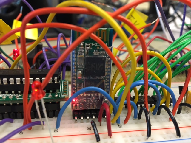 Figure 11: Bluetooth Communication with Pic In integration, we hoped to have bluetooth control whether effects should come from the digital effects or distortion, both driven from output of the tonestack, or sound from just the tonestack. We were able to confirm that our multiplexer control of the circuit, with select signals from bluetooth, was able to select which input to drive the class D amplifier with. In addition, in develoopment, integration had completely worked before perfboarding the tonestack. However, after the aformentioned AC-DC spike, some parts failed, and integration had not worked. In addition, power may not have been consistent enough from an AC power supply to give the desired outputs. When outputs were reached, some appeared to be very noisy. Integration is a big goal for future improvements of this project. We hope to PCB all circuits and ensure consisency in integration
Gallery
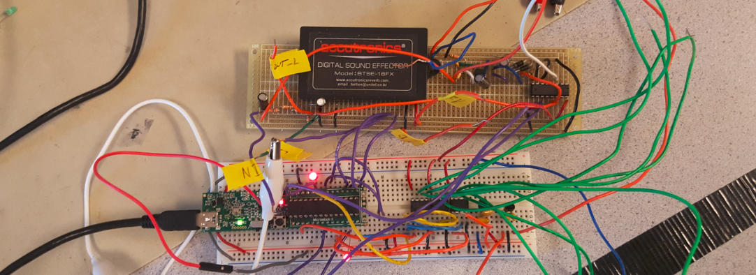 Figure 12: Pic32, Digipot, DSP Chip, Distortion, and Mux
 Figure 1: Initial Design Idea
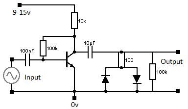 Figure 2: Distortion Schematic
 Figure 3: Tonestack Schematic
 Figure 4: Class-D Amplifier Schematic
 Figure 5: Digital Sound Effector Chip
 Figure 6: Wiring Schematic
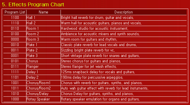 Figure 7: 16 Digital Effects Control With 4-Bit Signal
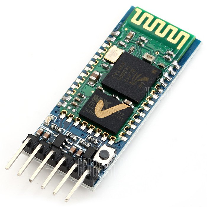 Figure 8: HC-05 bluetooth Module
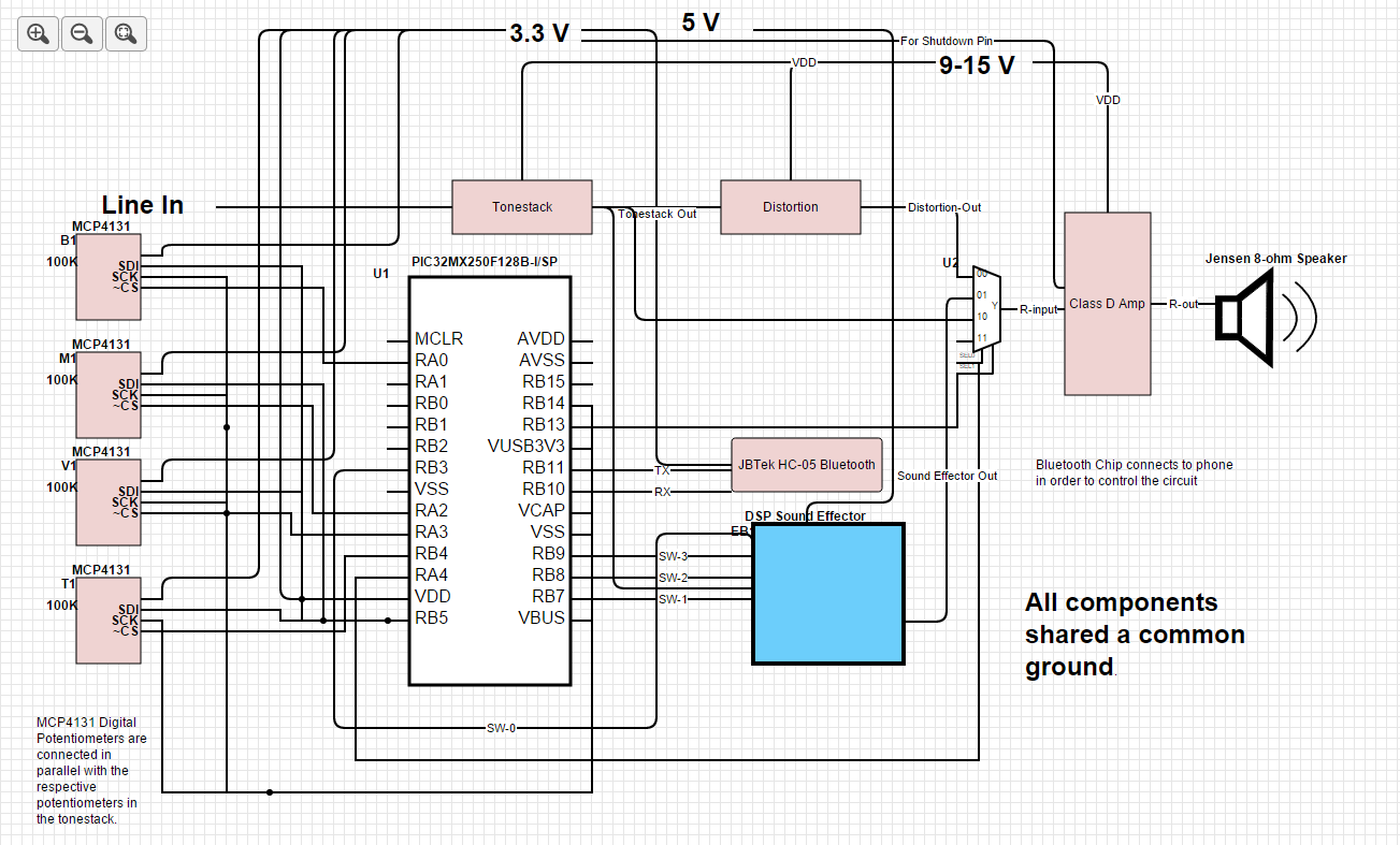 Figure 9: Overall Schematic of Project
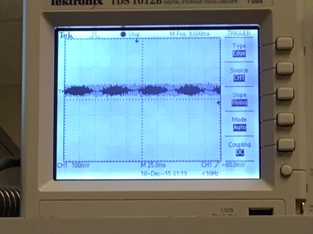 Figure 13: 550 Hz Sinusoid input into DSP chip
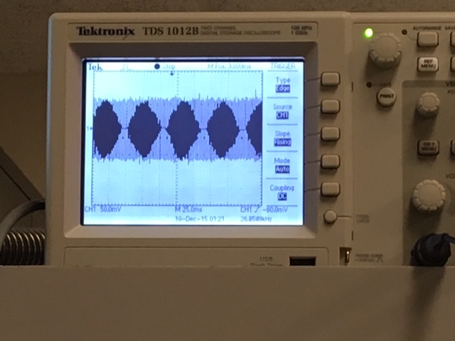 Figure 14: Output of Digital effect 3.
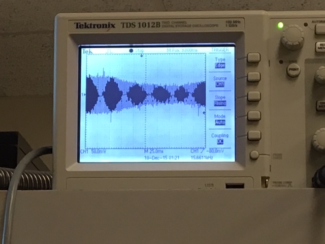 Figure 15: Output of Digital effect 12.
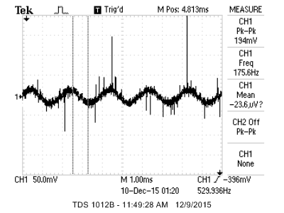 Figure 16: High Bass
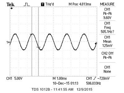 Figure 17: High Level
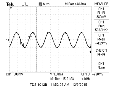 Figure 18: High Treble
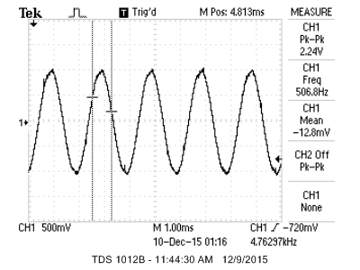 Figure 19: Mid High
 Figure 20: Mid Level
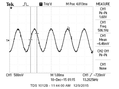 Figure 21: Mid Mid
 Figure 22: Low Bass
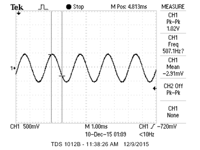 Figure 23: Low Level
 Figure 24: Low Treble
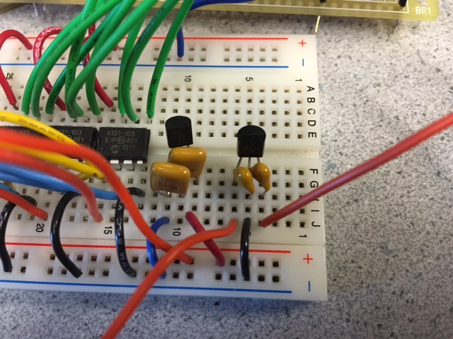 Figure 25: Voltage Regulators on Breadboard