Our project designs a touch piano with 3 octaves (37 keys) by connecting a handmade piano-like touch-sensitive keyboard with a PIC32 microcontroller. The sound is generated by using Karplus-Strong algorithm with debounce function and with a sensitive reaction time of several hundred microseconds.
Lab Demonstration
Key points for this design are implementation of capacitive sensor, sound generation by Karplus-Strong algorithm, keyboard building and other detailed problems including keyboard debounce, sound tones, sound lasting time, etc.
The main touch function of this capacitive sensor is implemented by measuring the capacitance difference between the foil touched or not. When human touch the foil, the capacitance of human body is paralleled with the original capacitance of the touch keyboard (the foil), which reduces the original capacitance. By applying the CTMU function combined with ADC function, we could detect this capacitance variance as the touch signal thus achieves the function of touch keyboard.
Then another key focus is the sound generation by the Karplus-Strong algorithm, which is a plucked string synthesis suited to be implemented on the microcontroller. We also add debounce function for avoiding annoying consecutive sharp sounds by one touch and our design could generate chord up to four tones.
The final job is the design and building the keyboard. The basic thought is using silver Aluminum foil for white keys and copper tap with black tap for black keys. The base is a piece of wood board and other hardware such as PIC32 and muxes are mounted on the back of the keyboard thus the keyboard is compact with an elegant appearance.
High Level Design
Source of Project Idea
With a much more powerful microcontroller this year, we thought we should be able to do quite decent music synthesis and generate many sounds with different frequency and tones at the same time. After checking the datasheet of PIC32, we learnt that the CTMU that can generate accurate and stable current can be used in implementing the capacitive sensor. And from matlab simulation, we also learnt that the Karplus-Strong algorithm is suitable for effectively generating sounds similar to piano. Thus we plan to build a touch keyboard by using capacitive sensors with the Karplus-Strong algorithm for sound generation.
Rationale and Background Math
Capacitive Sensor
In our project, we used capacitive sensing buttons as keys on the piano keyboard. More specifically, we use copper tape and aluminum foil as capacitive sensor since it can be easily found in the lab. When we touch these metal pads with finger, the capacitance will increase due to human’s capacitance. Therefore, we can take full use of this characteristic to trigger a sound when people touch it. The main idea is to let the microcontroller detects the capacitance of the metal pads. If the capacitance increases, then it means someone is touching the pads. To realize that we can charge the metal pads with constant current, and read the voltage after a while to get relative value of capacity.
See the figure bellow. Assume the blue one stands for the charging curve of metal pads. When we touch it by finger, the charging curve becomes the red one since a larger value of capacitance makes the charging process slower. Then, if we read the values of them at the same time, say t0, we can get V0 and V1 respectively for these two situations. We can use these two values to trigger and stop the sound generation. To realize this method, we use CTMU as the constant current supply and ADC to read the value. CTMU can provide a precise current; it can be used together with ADC which makes it suitable to be used in capacitive sensing. ADC can be used for obtaining the voltage value from pins. It requires no more further calculation since what we need are just relative values used in the judgment of triggering sound.
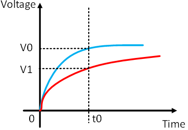
Figure 1. Capacitance charging curve
Karplus-Strong Algorithm
This part introduced the fundamental principle about the plucked string algorithm—Karplus-Strong algorithm. It is particularly well suited for implementing the digital waveguide for musical instrument synthesis on a microcontroller.
For the Karplus-Strong algorithm, the variable pluck, which means the energy stored in real string under every frequency, is simulated by filling the delay-line with the original noise table at the beginning of each plunk. In a real sound generation condition, vibration eliminates those frequencies introduced by the pluck that don't match the normal modes of the string. Friction and losses at end point will create the sound decay, and the sound with higher frequencies decays faster than lower ones. Finally, the wave shape will almost be sinusoidal with a period corresponding to the fundamental mode of the string. The sound will finally decay to silence. In the Karplus-Strong model this can be achieved by the introduction of an averager in the loop.

Figure 2. Karplus-Strong algorithm diagram
Alex Strong device filters by simply adding the two last outputs and right shifting the result which is divided by two. The just created sample is then re-introduced in the loop. This and the length of the loop will cause self-cancellation of the "non-harmonic" partials, which will also cause higher frequencies to decay more and more at each delay-line trip, until only the fundamental remain. It is just like in the case of a real string—the delay-line content will finally decay to a constant value, which sounds like silence.
The period of the resulting signal is the period of the delay line plus the average group delay of the filter; the fundamental frequency, as usual, is the reciprocal of the period. The required delay D for a given fundamental frequency F1 is therefore calculated according to D = Fs / F1 where Fs is the sampling frequency. And in our design, the variable string length which is stored in array note is the delay D mentioned before. So here, the equation for sound frequency is F1 = Fs / note.
Logical Structure
The high level structure of our project is shown in the figure below. We use 5 multiplexers as pin extension and get 40 pins totally. We connect 37 pins of them to the piano keyboard as 37 keys that are 3 octaves. ADC and CTMU are used together to get relative capacitance values through analog pins on PIC32. A speaker is also connected to the microcontroller as the output device.
When this device is running, PIC32 will scan all 40 pins one by one repeatedly to get the ADC value. Once a touch on the keyboard is detected, PIC32 will generate a corresponding sound calculated by using Karplus-Strong algorithm. The sound, which is a PWM waveform, will finally be output through speaker. Since the device is running at a really high speed, people cannot detect the latency between key pressing and the sound generation, which makes it more like a piano.
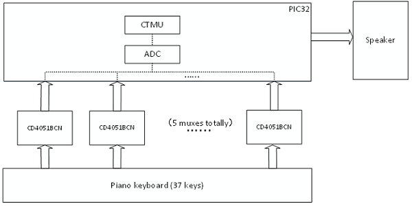
Figure 3. High level logic diagram
Hardware and Software Tradeoffs
PIC32 only has certain amount of ADC input ports, this prevents us from implementing more keys. Port mapping conflicts make it almost always impossible to have all of them available. One multiplexer occupies one port, and we used 5 of them.
We initially planned to connect a TFT screen to display sheet music as music is played. But as we allow our keyboard to play chord, we realized it would be quite hard to make the program to memorize the chord. Moreover, it is quite difficult to do the timing when displaying the music. So we gave up on this idea.
Software and Hardware Design
Software Design
Key Scanning
In our project, we enabled 37 capacitive sensing buttons to work together, which means the key scanning scheme should be not only reliable but also run at a very high speed. Therefore, we use a two-level loop to realize it. The outer loop is in charge of changing ADC channels. When the scanning of eight pins on one multiplexer is done, we change ADC channel for the next multiplexer by reconfiguring ADC. Since there are five multiplexers connected to the microcontroller, we enable five analog channels in turns to make sure that all these multiplexers can be reached. The inner loop is responsible for scanning eight pins on each multiplexer. Given that pins are selected through address, we enable three digital output pins on microcontroller to generate address signal for all 5 multiplexers. It is OK to connect all multiplexers with the same address signal because there is only one multiplier working at the same time. By this two-level loop method, each key can be scanned periodically with equal priority.
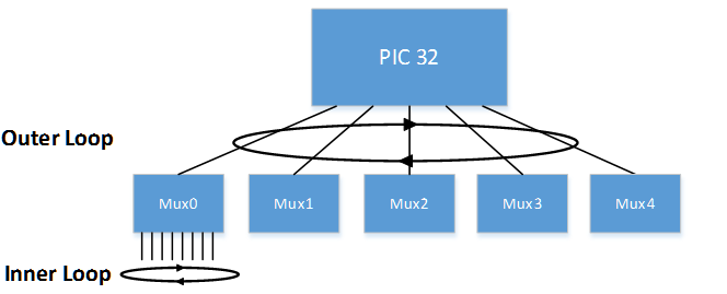
Figure 4. Software schematic diagram
Capacity Measurement
For this part, we referred to the CTMU section on ECE4760 webpage and used related code in it as the prototype of our code. See the link here
Capacity measurement operates in the inner loop of key scanning. When a certain key is selected, it won’t be changed to another one until the measurement on this key is completed. To realize what described in the high level design section, we use CTMU as a precise current source and ADC to measure the value of voltage. These two parts are inside PIC32 microcontroller and thus no peripheral circuit is required to be built. The general process can be divided into three stages. In the first stages we discharge the pins and wait for its completion. The discharging can be enabled or disabled by setting corresponding bit of CTMU. The time delay is generated by setting timer3. The second stage is the charging stage. This stage is very similar to the discharging stage, and the charging process is also managed by setting CTMU. We do measurement in the last stage. To get the ADC value, we should first start the conversion of ADC manually and wait until it is done by detecting the related bit of ADC. Then we read the ADC value and store it in an array which will be used later. The array we used to keep the value is a 40-element array so that the value read from each key can be stored in its corresponding place. By the way, no calculations are required to transform the voltage value into capacity since what we need is merely a relative value to detect whether people touch the keys or not.
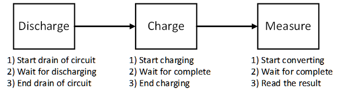
Figure 5. Capacity measuring process diagram
What should be stressed in capacity measurement is the time delay in the first two stages. Our device must run with little delay since we want to make sure that the latency between the touch and sound generation is hard for people to detect. As a result, we need to shorten the time delay by carefully setting the delay time of charging and discharging. After calculation, we set the charging time to be 2 microseconds to make sure the value from ADC won’t exceed its upper bound. Theoretically, the discharging time can be lower than 2 microseconds to make it fully discharged. We use Timer3 as a result to generate the delay of discharging process and yield time for the running of other threads.
Sound Triggering
After obtaining values from capacity measurement process, we use it as a trigger for the sound generation. In our program, the sound generation is started by inputting a saw wave table to the interrupt service routine (We name this process as “pluck” hereinafter). That is, we should use the value we get to make decision as to whether we do pluck or not. According the theory we mentioned in high level design section, the value from ADC will decrease when keys are touched due to the increase of capacity. We will call the value before and after touched as touch value and non-touch value hereinafter. In practice, the touch value is relatively stable while the non-touch value oscillates and different to some degree according to the structure of device and the person that touches it. Therefore, we need to carefully determine the value involved in condition judgement to make sure the sound generation can be triggered correctly when people touch it and stop when release.
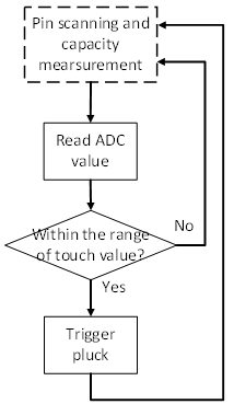
Figure 6. Sound triggering state diagram
After the sound triggering works fine, we then add debounce to it. Debounce is aimed to guarantee that the sound generation will be triggered once when a certain key is touched and won’t be triggered anymore unless we release our finger from the keyboard. This function is an indispensable part in our project since it is terrible if sounds are generated multiple times intermittently when we only press keys once. To implement this function, we use a finite state machine in the sound triggering part. The general idea is to let the actually pluck only happen once when the value read from ADC drops to the low level and never do it again until the value rebound to high.
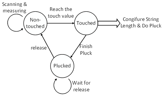
Figure 7. debounce state machine diagram
Interrupt Service Routine(ISR) Configuration
The reference code is in the DSP page—Sound synthesis: Karplus-Strong Algorithm, digital waveguides part. The corresponding link is here. For our design ambition, we compose the ISR for generating 37 tones from C3 to C6. In this design, The Karplus-Strong algorithm was implemented within the interruption generated by timer2 with a sample rate of 20kHz. And for generating tones with different frequency (from C3 to C6), we set different string lengths when detecting different keypad touch and the string length is provided in an array. In our code, as introduced before, the lowpass filter is determined by the damping parameter and the corresponding positive feedback loop is built for sound synthesis. Then we update and wrap circular pointers for further continuous calculation. When doing plunk, the program copies the noise table into string array for calculation. After the table copying, we then reset the point for this new sound data calculation and eliminate the set variable (plunk) to avoid incorrect continuous sound calculation and generation.
As for the selection of noise table, we tried five different sounds including white noise, gauss noise, sawtooth wave, triangle wave and sine wave. These noise tables are source array for generating different kinds of sounds after the operation of delay, lowpass and composition. By comparing these sounds by ears, we found that the sound generated by the sawtooth wave is the most similar one to the piano sound, thus we chose sawtooth wave as our excitation sound.
The noise table is built in the main function. It is an array with 256 elements containing sawtooth wave. Furthermore, we also set some variables for the initial configuration about the sound generation function in main function. The circular pointer for the original data—the noise table, the intermediate variables (lowpass filter input and output) and the plunk should be set to zero to ensure the accurate calculation for the first sound. The variable tune is used to alter the timbre of the sounds which could slightly modify the tone quality. The variable damping determinates the last time for one operation (one plunk). Here we also choose the optimum value to get the sound similar to the piano tones. As the output source, the PWM wave is set to OC2, which is opened and connected to pin 14 in the main function as well. The timer is also being setup here with interrupt with a generate period of 2000, which constrains the PWM sample frequency to 20KHz.
Chord Generation
After the configuration process and generating ono sound successfully, the next milestone is to implement chords generation. As for the requirement of playing the piano, we believe that chord up to four sounds is suitable. The idea is that we simulate up to four strings at the same time, and add the value to be outputted from each string together to generate the desired chord. To implement it, we use a 40-element array to store the value read from ADC. Instead of doing pluck as soon as we get a touch value, we scan all keys and then do pluck together for four calculation units. Once a touch value is detected during scanning, we set a string length according which key it is and move to the next string length configuration unit waiting for another touch value. Therefore, in this process, the number of enabled string is equal to the number of touch value we detected by ADC. After scanning all keys, we do pluck no matter how many touch value we obtain. Even if there is no touch value in this cycle, we do pluck with no string length assignment which also means no sound will be generated.
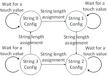
Figure 8. Chord generation state machine diagram
Hardware Design
Electrical Components
The electronic hardware we used are mainly about PIC32 microcontroller, 8 to 1 multiplexers and a speaker. As introduced before, we used five 8 to 1 muxes to achieve the 37 touch keypad input. Key part for the electrical component’s connection is the debugging and connection of the five multiplexers. As showed in the picture, the output pins of these five muxes are connected to five different AN pins in the PIC32 microcontroller as raw ADC data for analysis. The eight input pins are connected to the keyboard. Three pins on the PIC32 microcontroller are used for multiplexing for these five multiplexers. Furthermore, these muxes requires 3.3V voltage; pin Vss and pin INH need to be connected to the ground. And as introduced before, pin 14 is set as the PWM output, so we connect this pin to the speaker for outputting sounds.
Finally, in order to have reliable electrical contact, all electrical components including the PIC32 microcontroller, muxes and wires for connection are soldered on the solder board. The testing of this hardware is tedious at first. But after we finish the soldering process, it became a stable integrated component and worked pretty well.
Keyboaord Design
The design of the keyboard is also a hard work. To make the final outcome elegant, we tried to simulate the appearance of the true piano. Key points here are that we have to find some kind of metal for building the capacitive sensor. At first, we test the function by applying coins, to be specific, pennies. Later we used aluminum tape for white keys and copper tape for black keys, which looks better. A thin wood board is bought for the fundamental base of the keyboard. We cut the tape to the standard width and length for the actual piano keyboard and stick them on the wood board. Finally we cut out the extra part of the wood board and make stands for it. Then we finish our design by mapping these wires for corresponding keypads. Finally we used black tap to fix the electrical components on the back of the keyboard and connect input wires to the corresponding keypads on the board. We integrated the electrical parts with the wood board based keyboard to finish our design. The following are the pictures of our final product.
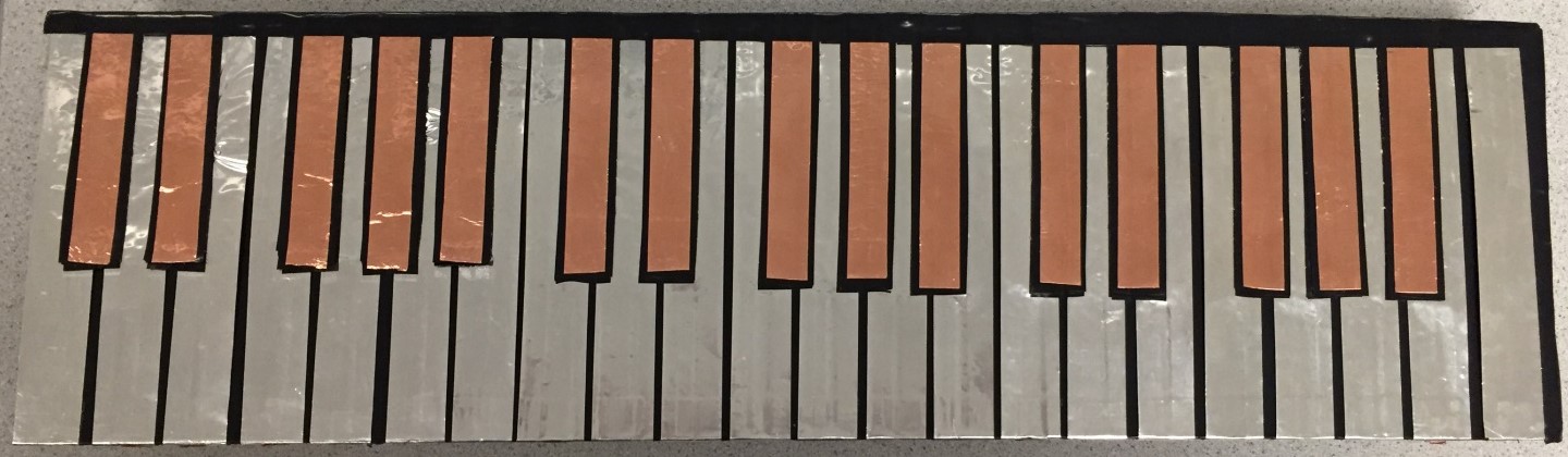
Figure 9. Front of the keyboard (touch keypad)
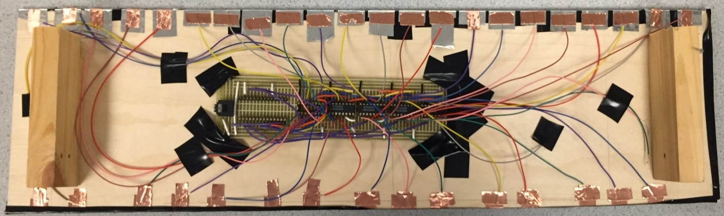
Figure 10. Back of the keyboard (electrical components)
Results
In this design, we applied the incremental design methodology. Just as introduced in the program and hardware design, we first implemented the function of capacitive sensor, then generated sounds by Karplus-Strong Algorithm. Following are test results chronologically.
ADC Data
From the following two pictures, we can learn that the normal (without touch) ADC value is over 400; and when we touch the port, the value would decrease to a little above 200. By detecting this difference, we can implement a touch-sensible capacitive sensor for building a touch keyboard.
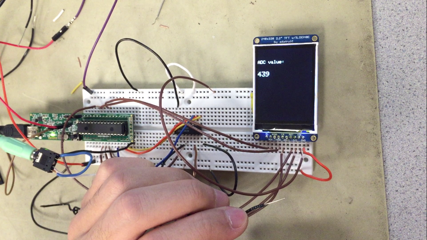
Figure 11. ADC value (without touch)
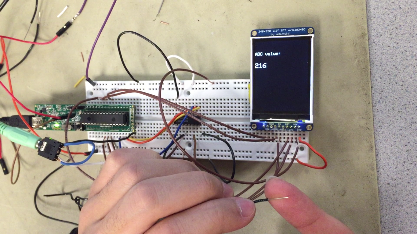
Figure 12. ADC value (with touch)
Scan Time
In order to measure the scanning time for one cycle (5 multiplexers, 40 keys), we had to modify our source code. One unused pin RB4 was set as output; when one cycle’s scanning finished, we toggle this pin (reversal the voltage level) so that we got the following pulse wave. And the half of its period was the scanning time, which is 7.6ms for 40 keys (0.19ms for one key). This is fast enough for our design.
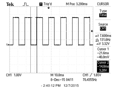
Figure 13. Scanning time for 40 keys
Sound Generation
After we successfully built the scanning system for generating 37 sounds, we used oscilloscope to test the accuracy of our tones. The following picture shows the actual frequency of C4, which is 263.2Hz. Compared to the actual frequency which is 261.1Hz, the frequency we get is accurate enough and the percentage error is only 0.8%.
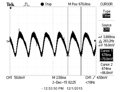
Figure 14. Frequency measurement for C4
And the following picture is the overall waveform for one note (C4). When we zoom out the oscilloscope and trigger the sound, we can get the waveform of one tune. From the picture we can learn that after the trigger, the sound ramped to a high level of intensity, and lasted for some time and then slowly attenuate to disappear. This picture is similar to the simulation result of Karplus-Strong Algorithm sound generation by the Matlab. So these results verify the accuracy of our tunes generated by Karplus-Strong Algorithm.
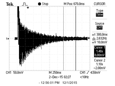
Figure 15. Overall waveform for C4
Conclusions
We built a touch piano with a keyboard of 37 keys in our project that can be played like a real piano with a touch keyboard. The pin scanning is fast enough to avoid a detectable latency between touching and response. Karplus-strong algorithm with different string length configuration meets the frequency accuracy requirement of each note and the sound effect is really like piano. In addition, we write code for debounce and for playing chord to fulfill the requirement that a real piano can achieve which enables both-hand playing. In capacitance measurement part and sound generation part, we refer to relevant codes on ECE4760 webpages and modified them for our usage. Thanks to that, we finish our project successfully with all basic requirements met.
However, there are also many places that remain to be improved. For example, we have not simulated the paddle, which is another crucial part of piano. Our sound synthesis algorithm is not good enough to produce a real piano’s sound. To achieve that, more complicated method should be developed and used. Our touch piano can only simulate one sound effect due to the limitation of time. More work and time can be spent here to add more sound like organ, guitar and violin into our project.
Ethical Consideration
When we designing our project, the IEEE code of ethics are something we carefully considered. There are several specific IEEE codes we covered that were particularly relevant to our project. We had learnt a lot from this final design and increased our technical competence. In specific, we improved our abilities about C programming, hardware connection and especially the application of PIC32 microcontrollers. When designing our project, we took safety seriously and never attempted anything that would endanger ourselves or people around us. When soldering the electronical components onto the solder board, we used the glasses to protect our eyes and carefully did the work. It is impossible to achieve our goal without the help from our professor and his teaching assistants. So at last, we conform again that we took responsibility in making decisions consistent with the safety, health, and to disclose promptly factors that might endanger the public or the environment. And we are honest and realistic in stating claims or doing estimations based on available data. As a team, we closely coordinated with each other to seek methods to acknowledge and correct errors. So our final design—the touch piano, is a safe product that does not endanger others, their property, or reputation.
Appendices
A. Source Codes
We only include the code we write here. As for other included files, like config.h, tft_master.h, pt_cornell_1_2.h, they change over time and we did not write them. If you want to have a look at them, you can find them on ECE4760 web page.
- main.c (15 KB)
B. Schematics
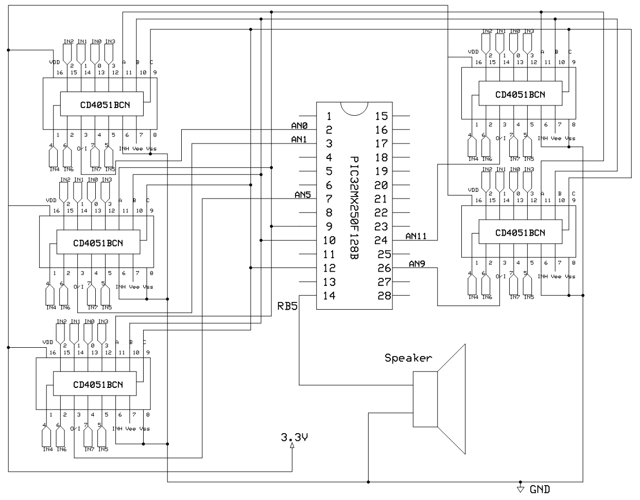
Figure 16: Circuit Schematic
C. Parts List and Cost
Our total cost for this project came out to be $38.45. Our cost breakdown is listed below:
| Part | Source | Quantity | Unit Price | Total Price |
|---|---|---|---|---|
| Microstick II | Lab stock | 1 | $10 | $10 |
| Solder board | Lab stock | 1 | $2.5 | $2.5 |
| Pic32MX250F128B | Lab stock | 1 | $5 | $5 |
| Sip or header socket/plug | Lab stock | 108 | $0.05 | $5.4 |
| Wood board | Lab stock | 1 | $10 | $10 |
| CD4051BCN | Lab stock | 5 | $1.11 | $5.55 |
| Wires, tape | Lab stock | many | %0 | $0 |
| Total Cost | $38.45 |
D. Labor Division
Wendian Jiang: CTMU code, debounce code, multi-tone code, help on hardware construction
Hanchen Jin: Karplus-Strong code, code optimization, report, hardware design and construction
Lin Wang: Karplus-Strong code, report, code optimization, help on hardware construction, web page design
References
- Karplus Strong (Wikipedia)
- DSP for GCC (ECE4760 course page)
- Karplus Strong C Code (ECE 4760 course page)
- PIC32MX250F128B (Microcontroller)
- CD4051BCN data sheet (8 to 1 multiplexer)
- Protothreads reference manual
- PIC32MX2XX data sheet
- PIC32 family reference manual
- MPLAB XC32 compiler user's guide
- PIC32 Plib guide
- CTMU (ECE4760 course page)