3D Mouse App
Chang Liu (cl2428), Pei Xu(px29),
Zhenzhen Lin (zl482)
Introduction
We design a wireless 3D mouse to control a music player to change songs and stop and play the song. The 3D mouse responds to all-direction movements as it has a built-in accelerometer. The user gives the commands by moving this mouse to the direction he or she wants. In addition, if we move the mouse downwards it will send the command of conformation to the processor. For example, if the user moves the mouse from left to right, the cursor on the screen will go rightwards.
Our team implement a music player application controlled by the mouse. There are two buttons on the display, one is ‘Next song’ and the other is ‘Pause/play’ button. After the user moves the mouse to control the cursor to either of the button, the user can give the command of push the button by moving the 3D mouse downwards.
The music player is built using a stand along PIC32 chip connecting with a 12 bit DAC and a micro SD card. The circuit is referred to the project Tahmid Syed built before. See the link. We realize the wireless data transmission by connecting NRF24201 wireless transceiver to the transceiver side (3D mouse) and receiver (Microstick II).
High level design
Below is our system block diagram
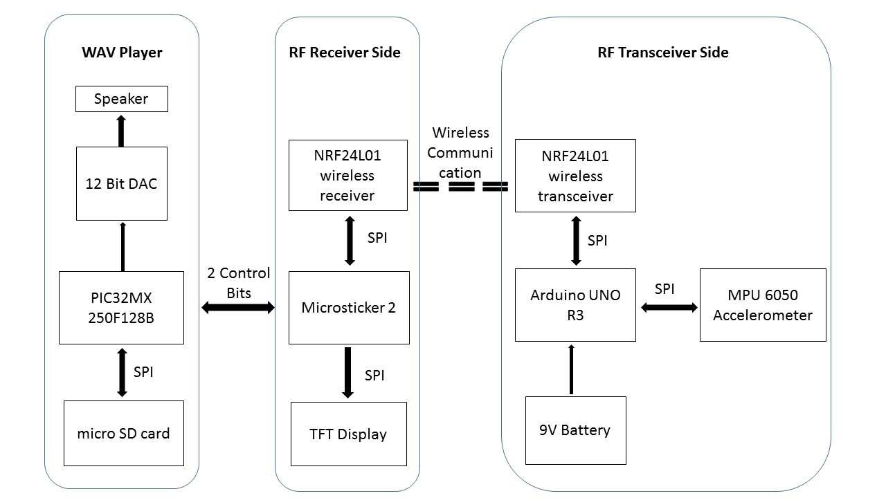
Figure 1: System Block Diagram
Our project consists of three main parts: RF transceiver side, RF receiver side and PIC wav player. In the RF transceiver side, we use Arduino Uno R3 as microcontroller which is responsible for processing the data sent by MPU6050 Accelerometer and then sending the processed data to NRF24L01 RF transceiver. We apply an external 9-volt battery to Arduino Uno R3 as power supply.
RF receiver side use MicrostickII as microcontroller which can receive data from NRF24L01 RF transceiver and control the movement of cursor on the TFT screen. The actual movement is decided by the accelerometer connected with the RF transceiver. MicrostickII and Arduino Uno R3 exchange data using NRF24L01 radio frequency chip through SPI communication channel.
On the PIC wav player side, PIC32 is connected with a 12 bit DAC and a Micro SD card. The SD card is used to store the music files. The PIC searches the file names in micro SD card and sends the data to DAC. The converted signal can be played by speaker. PIC32 and MicrostickII connects using 2 control bits which enable the MicrostickII pass commands to PIC wav player.
RF transceiver side
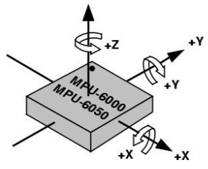
MPU 6050 Accelerometer and Gyro is employed to detect the human motions:
 |
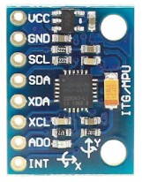 |
Figure 2: MPU6050 Sensor Axis Direction and Polarity of Rotation from reference 6
MPU 6050 Accelerometer and Gyro is a combination of 3-axis accelerometer, a 3-axis gyroscope and a DMP (digital motion processor). The MPU6050 library we use is written by Jeff Rowberg
link.
The data transfer rate we use for writing to registers is 400 kHz via I2C. The MPU6050 uses three 16-bit ADCs for gyroscope and accelerometer respectively to convert the measured analog value to a digital value. Accelerometer can measure the range of ± 2, ± 4, ± 8, ± 16g. In our case, we apply the accelerometer ± 2 as the measurement range.
NRF24L01 Radio Frequency Transceiver is used to send data wirelessly:
Figure 3: NRF24L01 Radio Frequency Transceiver
The communication between MicrostickII and Arduino Uno R3 is realized through two NRF24L01 RF transceivers. NRF24L01 transceiver module communicates with MCU through SPI. And we transmit data using RF pipe 1. The library we use is an open source library from GitHub link.
In the project, we only use accelerometer to get the acceleration on X, Y, Z axis. The movement of cursor only depends on the X and Y axis acceleration of MPU6050. Keeping the MPU6050 at the horizontal level, the accelerations on X and Y axis are 0 with a gravitational acceleration along –z axis. Since we choose 0 for AFS_SEL to get the highest precision, the read value on z axis is around -16384 if holding the chip at the horizontal level. We defined the right as the positive X direction and forward as the positive Y direction.
The accelerations on X, Y plane are scaled to the moving velocity of cursor on the TFT screen. There totally three levels of speed: rest, low speed, high speed. When the measured absolute values are both smaller than 5000 on X and Y axis which means the chip is almost parallel to horizontal level and return 0 for both axis. When the measured absolute value is bigger than 5000 and smaller than 11000, we return 1 and give low speed along the measured axis. When the measured absolute value is bigger than 11000, we return 2 and give high speed along the measured axis. The speed levels along X and Y axis are respectively stored into the first digit and the second digit of the data set.
According to X and Y axis, we divide the plane into four quadrants and give value 1 for positive X and positive Y quadrant, 2 for negative X and positive Y quadrant, 3 for negative X and negative Y quadrant, and 4 for positive X and negative Y quadrant. If the acceleration value is 0 along X or Y axis, we divide the direction into either quadrant only relying on the direction of nonzero axis. We stored the return value into the third digit of data set which represents the motion direction of cursor.
The Z position works as a push button. Since there is a gravitational acceleration along –z at rest, we send the command of pushing button only when the acceleration value is much bigger than 1g along –z axis.
RF Receiver Side
RF receiver side uses MicrostickII as microcontroller which can receive data from NRF24L01 RF transceiver and control the movement of the cursor on the TFT screen.
NRF24L01 communicate with the PIC MCU via SPI channel 1.
• Pin 3 RPA1 --> MOSI on NRF24L01
• Pin 5 RPB1 --> CS on NRF24L01
• Pin 6 RPB2 --> CE on NRF24L01
• Pin 17 RPB8 --> MISO on NRF24L01
• Pin 25 RPB14 --> SCLK on NRF24L01
The TFT screen uses the SPI channel 2 on MicrostickII. The circuit connection is as follows.
• Pin 2 RPA0 --> D/C on TFT
• Pin 4 RPB0 --> CS on TFT
• Pin 7 RPB3 --> RST on TFT
• Pin 22 RPB11 --> MOSI on TFT
• Pin 26 RPB15 --> SCLK on TFT
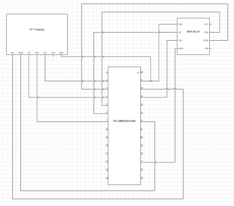
Figure 4: Pinout of RF Receiver
We implement nRF library which is provided by Nathan Spallone on ECE 4760 website. The movement equations of cursor is:
rx= rx + vx; (r is the position)
ry = ry + vy; (v is the measured velocity)
The initial conditions of position and velocity are set to the bottom of the TFT screen and zero respectively. The new position equals to the old position add the measured velocity which is the data sent by the RF transceiver. The measured velocity is resolved back into X and Y velocity components which can be read from the first three digits of data set. We erase the old position when the new position is different from the old position. The erase rate is the same as the frame rate. The unit of velocity is pixel per frame.
Wave Player
For the wav player we refer to the circuit designed by Tahmid Syed and use related code in it as the prototype of our code.
This music playback system receives commands from the RF receiver side. There are three commands sent by the RF receiver. The three commands are decoded within two control bits. Two digital output are set on the PIC in RF receiver which are RB4(pin11) and RB5(pin14). And two digital input are set on the music playback PIC microcontroller by writing 0 to TRIS B8(pin17), B9 (pin18) registers.
By setting two output ports to 00, 01 and 11, our team is able to send three different commands. The three commands are used to play the next song, pause the currently playing music and continue playing the paused music in the PIC wav player. Since the RF receiver may send control signal multiple times within one action, a finite state machine is employed to eliminate changing the state unexpectedly. Other two commands are stop and play commands sent by RF receiver station. The following diagram shows the detailed information of the state machine.
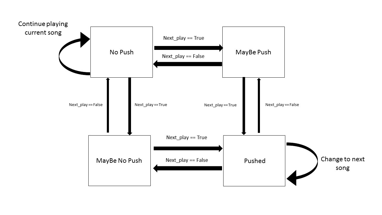
Figure 5: Finite State Machine for Wave Player
Results
The debug for MPU6050 accelerometer and gyro is not hard. We use serial monitor to read the measured value and make sure the value is as expected. MPU6050 is really sensitive and accurate. However, the debug of nRF communication is not so easy because the error of any side will contribute the communication failed. TA advised us to blink an attached LED if the received value is the same as the expected value.
PIC32 may compile unsuccessfully without any reason. Once PIC32 is compiled successfully, the wav player works properly. After debugging and testing, the system works as we expected. The 3D mouse is sensitive and stable. We use a plastic box as the case of 3D mouse to conceal the exposed wires. It is safe, reliable and tastefully displayed. A plastic case not only lowers the cost but also ensures that components are not easily damaged.
Conclusion
We reach the goal to make a practical and interesting 3D mouse. The 3D mouse can remote control the cursor on the TFT screen and play music. Although we have already make a wav player as application of 3D mouse, we can improve our project by developing more applications. It would make the system more interesting if we develop a specific game that can played using 3D mouse. In conclusion, the design and implement of system is success.
Team Contribution
Pei Xu: Circuit fabrication, RF debugging and web-page construction
Chang Liu: Wave player programming, RF receiver programming and debugging RF communication
ZhenZhen Lin: RF tranceiver, accelerometer programming and RF debugging
Acknowledgement
We are sincerely grateful to Professor Bruce Land in FALL 2016 semester for his help and guidance. We would also like to thank the lab TA's for their help in debugging and offered guidance for all regular labs as well as this final project. Additionally, we are also grateful to Nathan Spallone and Zhiyuan Teo for their effort to make RF24 library.