ECE 4760 Final Project Report
Programmable Sequenced Wavetable Synthesizer waveform1 waveform2


Authors


Table of Contents


Introduction

Soundbite

For our final project, we created a wavetable synthesizer capable of playing back short user-programmable sequences with a large range of timbres.

Summary

We decided to create a fun, easy-to-use wavetable synthesizer with just enough parameters to offer a large sonic range, while limiting the controls to keep the user interface clean and as unconfusing as possible. This goal was driven by the desire to make a useful product relevant to the current digital synthesizer market, an area in which wavetable synthesis is very popular. This method of synthesis allows for arbitrary waveforms, as well as blends of multiple waveforms, allowing for a number of tones only limited by the storage capacity of the device.
TOP

High-Level Design

Rationale

The motivation behind this final project was to design and build a cheap and easy-to-use sequenced wavetable synthesizer, primarily useful for basslines. It was mainly inspired by classic digital/digitally-assisted synthesizers like the PPG Wave, Waldorf Microwave, and Roland TB303. However, we wanted to make a wavetable synthesizer with simple, user-friendly controls, while still allowing the user to produce a wide range of sounds at a high audio quality. Wavetable synthesis, which is the method of repeating (and sometimes fading between) waveforms in tables in memory, is a very easy way to produce many timbres in software inexpensively, so it was an obvious choice for our synthesis engine.

Background Math

The main math used in this project was used over and over again to calculate phase accumulators for many aspects of the synthesis. Phase accumulators were needed for the C0-C4 note frequencies, for all the envelope keyframe speeds, and for the different tempos allowed by the sequencer. These were calculated by taking into account the overflow for our envelope/sequencer/oscillator phase accumulators, all of which were unsigned integers. The calculations also took into account the desired frequencies, and the frequency of the DDS ISR, which was run at 100kHz. A sample calculation of a phase accumulator for the note C1 is done below, and all other calculations, as well as comments on them, can be found in the 3 Ruby scripts found in the Commented Program Files section.

Calculating Phase Accumulator for the Note C1

phase accumulator calculation

Logical Structure

Our first step in approaching this design was to set up a DDS ISR and configure the DAC using methods similar to those used in the DMTF section of Lab 2. At this point, we wanted to make sure that we could fade between two different waveforms. Since we had no user input at this point, we instead created an LFO (low frequency oscillator) alongside the main oscillator, to use as a modulation source. After generating two tables, one with a triangle wave and the other with a sawtooth wave, we created a macro that took a blend index and output a blended sample. By indexing into both tables with our phase accumulator, then feeding the two retrieved samples into this macro along with the LFO’s value, we were able to achieve smooth crossfading between two waveforms.

Initial Triangle to Sawtooth Blend, Midway

triangle to sawtooth
After this initial success, we wanted to be able to blend through a whole wave table manually. After having created a C header file with all the samples needed for a simple wavetable, we added some bitwise logic to separate our crossfading signal into two parts: one part to index into subtables (individual waveforms), and another part to represent the fade index between the two subtables. Finally, we set up the ADC and connected it to one of our potentiometers, in a way similar to the paddle control potentiometer in Lab 3. Reading the ADC’s value in the DDS ISR, we were able to get very responsive fading across an entire wavetable.

Our next step was to add our sequencer. This was a pretty straightforward implementation, using another phase accumulator to represent the sequence position, which was updated in the DDS ISR depending on whether or not the sequence was playing. Alongside this development, we created the user interface needed to represent the sequence, so that the sequence’s status could be viewed on the TFT display.

Once we had the sequencer working, we added all the controls we needed, which were read through a multiplexer into the single on-board ADC on the PIC32. We managed to correctly implement this part of the project after much troubleshooting. We used the values we read in from the multiplexer to control sequencer speed (tempo), sequencer editing parameters, wave blending, and, envelopes. While initially, TFT updates happened in the DDS ISR to keep them synchronous with updates in the sequence, this became impractical, so they were moved to a dedicated thread. Button presses, and multiplexer input reading were also each given their own threads respectively. After a bit more work with reducing the complexity of envelopes, using a method which crossfaded between different envelope ‘keyframes’, we had a working program.

Hardware/Software Tradeoffs

The main hardware/software tradeoffs we dealt with revolved around amplitude control and the associated amplitude envelope generation for our synthesizer voice. Our amplitude control was implemented in software, using the DDS ISR and some shift operations/multiplication to scale the output sample by the amplitude envelope. This envelope was also generated in the ISR, with parameters calculated from values read in our knob value reading thread.

Generating the amplitude envelope using a hardware envelope generator circuit would have been more expensive and increased circuit complexity, but users would be able to have more control over the envelope shape. We had to compromise on envelope shape control for simplicity of user experience, as well as limited ADC capabilities. To scale the amplitude of the output audio in hardware, we would need to construct a VCA (voltage-controlled amplifier) circuit, using transistors, and OTA, or a dedicated VCA integrated circuit. This would have also added to costs and circuit complexity.

A small extra step would also need to be taken to allow for hardware generation of the amplitude envelope - since it would no longer be triggered in the ISR, it would not have access to the knowledge of when a step change in the sequence occurred. So, another digital output pin would have to be configured, and in the ISR a trigger would have to be sent out on this digital pin to trigger the amplitude envelope on active steps.

We were able to fit the amplitude scaling and envelope generation into the DDS ISR in software, reducing the customization of envelope shaping, but also greatly reducing the cost and circuit complexity of the final product.

Use of Existing Standards

We did not use any common standards for this project. One possible standard we could have used, has this been a keyboard-controlled synthesizer, would be MIDI. However, since we generate and modify our 16-step sequence internally, it does not make sense to use the MIDI standard to represent note onsets, offsets, and pitches.
TOP

Hardware/Software Design

Software Details

Synthesis/Sequencer Parameters

In our software, there are dozens of variables that refer to different synthesis parameters. Two char arrays, step_notes and steps_on, represent the note and 
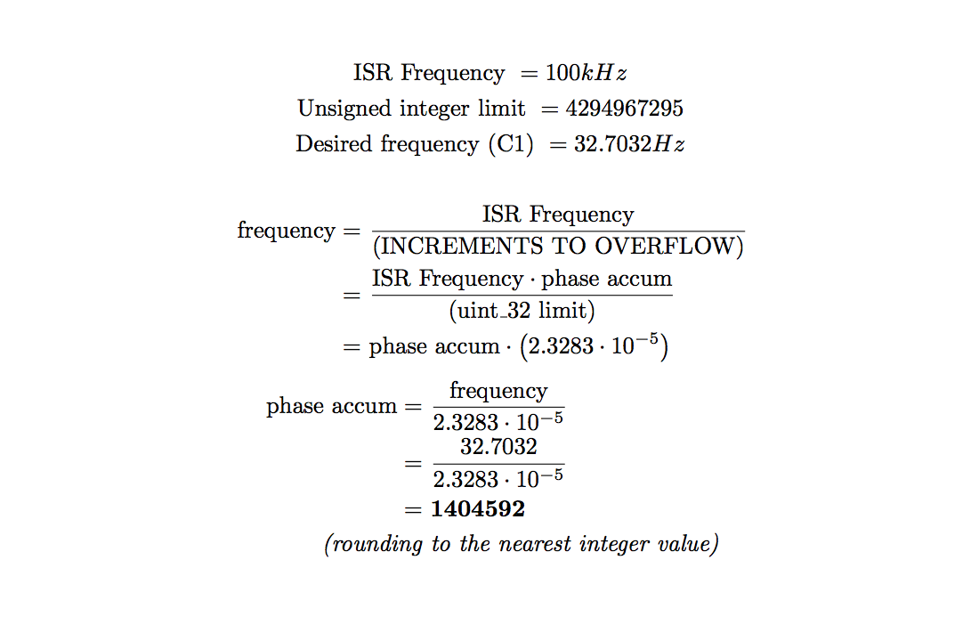
activity (rest or note) of each step in the 16-step sequence. In step_notes, a note is represented by an index, 0-48, into a table of phase accumulators, calculated using freq_accum_calcs.rb, which can be found in the Commented Program Files section.

The old_step_select, step_select, note_select, old_step, and curr_step variables are used for sequence editing and playback, both to supply the TFT-update thread with information it needs to draw the sequence state, and to facilitate reading and writing data to/from the two sequence arrays mentioned above. The seq_active variable is used in the DDS ISR to determine whether or not to add the sequence advancing phase accumulator to the step_accum counter. The phase accumulators for each tempo were calculated using tempo_accum_calcs.rb, which can be found in the Commented Program Files section.

There are many flags, accumulators, and values that go into making the amplitude and shape blend envelopes work. The amp_env, shape_env, and shape_amt variables hold the values for the modal envelopes, and the attenuation amount for the shape envelope respectively, all set directly from the ADC reading thread. The rising variables are used as flags in the DDS ISR to determine whether to add or subtract the accumulator. The rise_acc and fall_acc variables for both envelopes are set using envelope rise/fall phase accumulators calculated in env_bound_accum_calcs.rb, which can be found in the Commented Program Files section. These accumulators are blended across the turn of the modal envelope knobs, allowing fades through different envelope lengths and shapes.

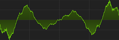
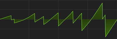
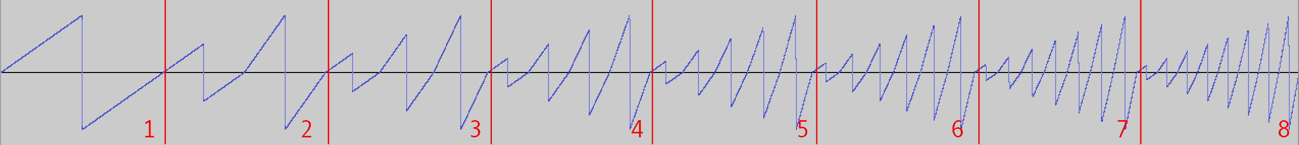
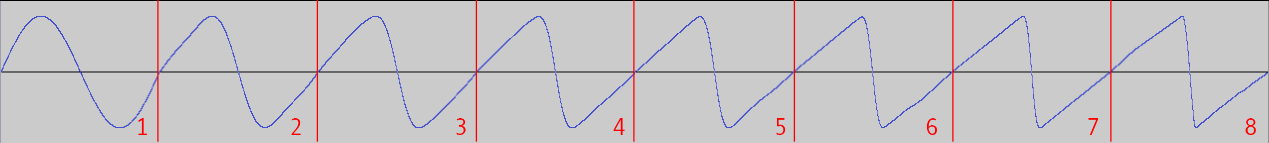
Both envelopes are AD envelopes. At the left side of the knob, the envelope has a short attack and long decay. As the knob moves towards the center of its turn, the decay becomes longer until a certain keyframe, at which point the attack starts lengthening, making the envelope's shape more triangular. After this keyframe, the attack continues to become longer as the decay shortens, eventually resulting in shapes inverse to those on the left side of the knob, in which the attack is long but the decay is very short. The specific time values of each envelope keyframe are listed in comments in env_bound_accum_calcs.rb.

DDS ISR

Our DDS ISR (Direct Digital Synthesis Interrupt Service Routine) accomplishes all the tasks it needs to very expediently. This is necessary because of the speed at which it is run: 100kHz. In these 400 cycles, with cycles to spare for other threads like the button, multiplexer, or TFT threads, the procedures executed are as follows:


Using integer operations instead of fix16 operations, as well as choosing scaling values to allow division using variable right shift, allowed the DDS ISR to function properly in the small window of time it was allowed.

TFT/User Interface

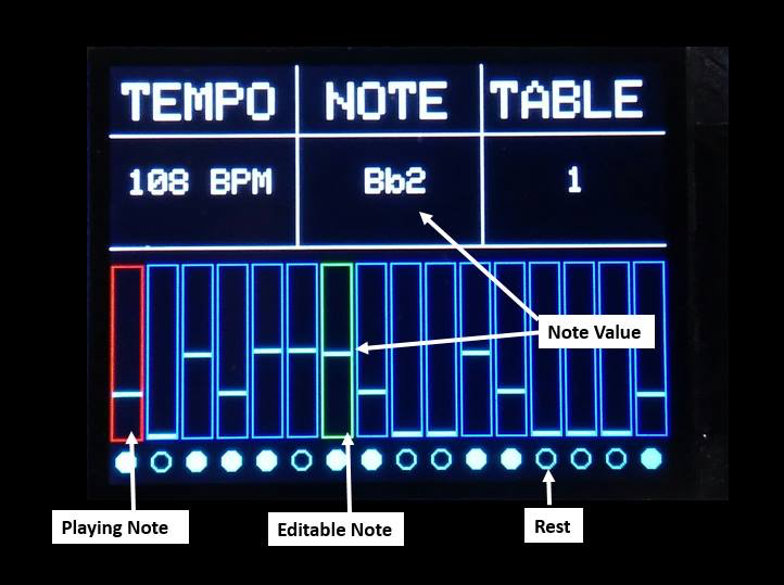
The intitial sequence state, as well as the general UI format, is drawn to the TFT using the helper function initTFT(), which is called from main. After this point, once threads have been scheduled and the program is fully started, the TFT is updated 20 times per second, using a dedicated TFT update thread.

In the TFT update thread, flags set in the ISR and the other threads allow for updating the sequence state only when necessary. Only steps which have changed will be redrawn, and the red/green selector boxes for selected and active sequence steps will only be moved if their positions have been changed. Copies of all flags which are set in the ISR, such as the old and current step, are made in the TFT update thread to ensure that their values don't change in between dependent drawing steps. The tempo, note-to-write, and table index are all rewritten each time the TFT update thread's loop executes.

User Interface on the TFT Display

tft user interface

Multiplexing Input

The multiplexing of input through the 1 on-board ADC was done in a dedicated thread. In this thread, all 7 potentiometer values were read into their respective variables, with any data manipulations needed done as well (such as converting raw envelope positions into rise/fall accumulators). The 3 control bits for the multiplexer had to be switched before each read, after which a couple short waits (implemented using an empty while loop) was required before reading the ADC value. Overall, the procedure for each of the 7 reads was largely identical and was as follows:


Button Processing

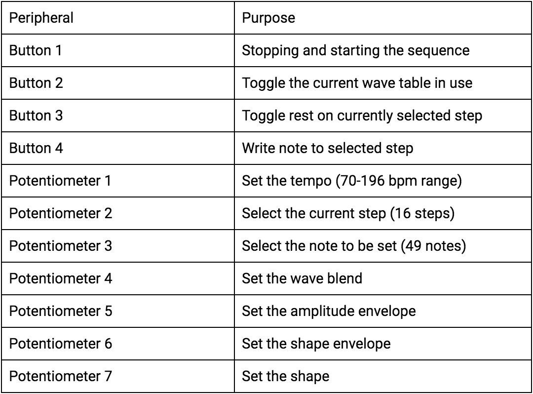
The four buttons were processed using a thread which was run at approximately 10Hz. Because of the slow rate of button value capture, we deemed it unnecessary to debounce the buttons. The button thread was, as a result, rather simple. For each button, the previous value of the button was stored. If the newly-read value of the button from its digital input pin was different from the previous value, and this new value signified that the button was being pressed, the data the button controlled would be modified. When writing a new note value, or changing a step's rest state, the button thread would set some flags for the TFT thread to notify it about which step had been changed, allowing the TFT thread to do less work.

Creating Wavetables

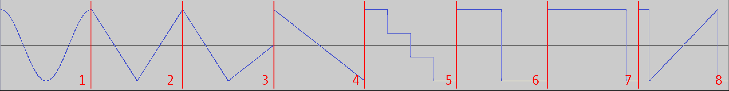
All of our wavetables were initially designed custom in the VST Plugin Serum by Xfer Records, an advanced wavetable synthesizer with a built-in wavetable creation tool. After these wavetables were created, the .wav files that represented them were converted to 32-bit signed .raw files using the free audio software, Audacity. The wavetables in Serum initially were represented as 32-bit float, with 512 samples per table. Using 8 waves per table, as we did, this meant that each wavetable had 4096 32-bit samples, resulting in around 16KB per table.

After being converted into .raw format, each wavetable was converted into a C header file using a custom command-line script, convert.cpp, which can be found in the Commented Program Files section. It allows the user to specify the name of the array in which the samples will be placed. We used these array names later in our int *tables array, which contained the four wavetables. The header files containing the wavetables were rather large, and as such have not been included in this report.

Use of unsigned ints instead of fix16

We decided to use unsigned integers to hold all of our synthesis parameters, even ones that would have to be scaled by others. We made this choice mainly to achive speed in the DDS ISR, for better audio fidelity via a higher sample rate and more time for threads to perform their respective tasks. The barrel shift allowed by the PIC32's ALU made division before scaling very fast, which came in handy for crossfading between waveshapes, fading between envelope keyframes, scaling shape modulation, and scaling the DDS sample by the amplitude envelope.

Configuring the DAC and ADC

The DAC and ADC were configured using code modified from examples on the course website. We put most of our configuration code in two functions, initADC and initDAC, which were both called from the main procedure of our program. We also used some macros for the bitwise ORs of configuration flags.

Hardware Details

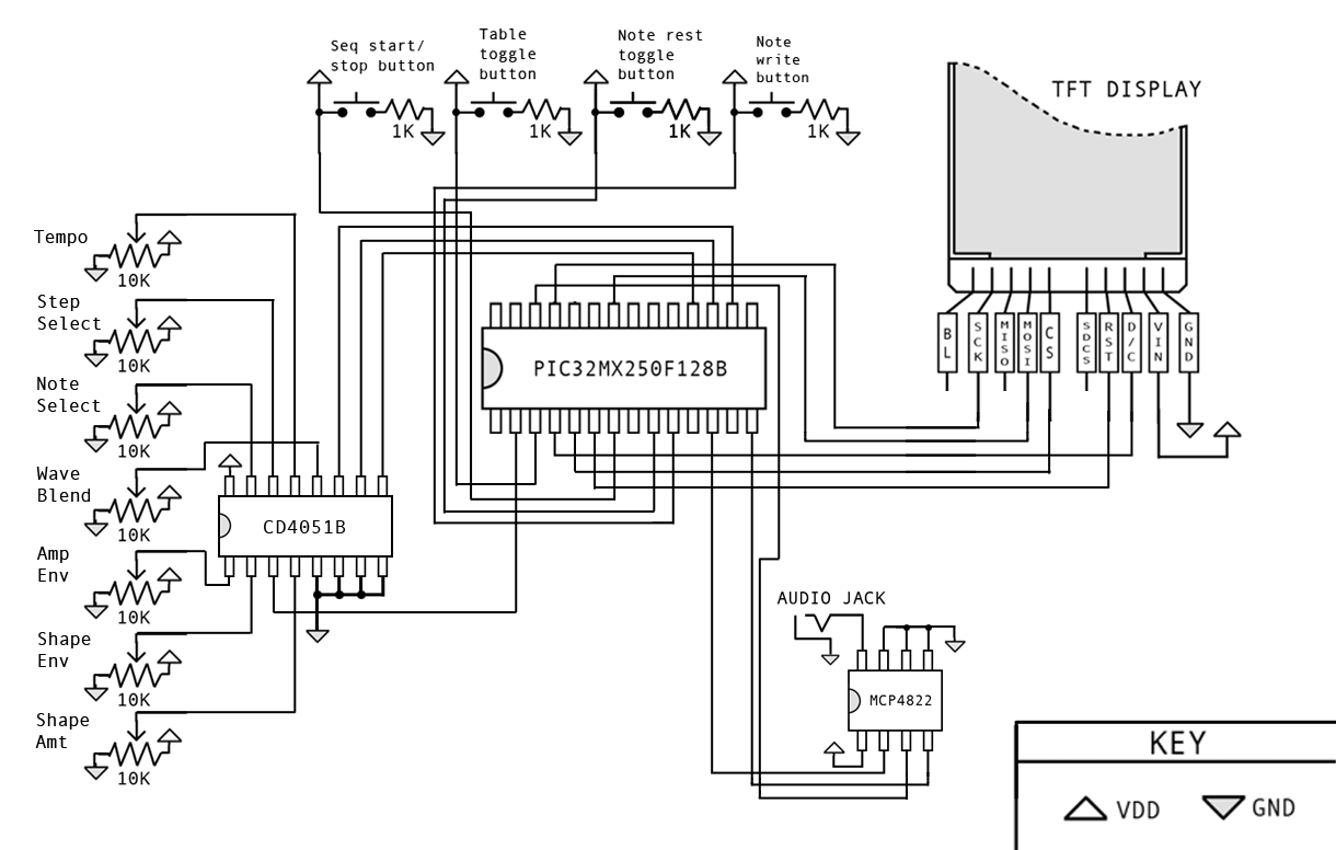
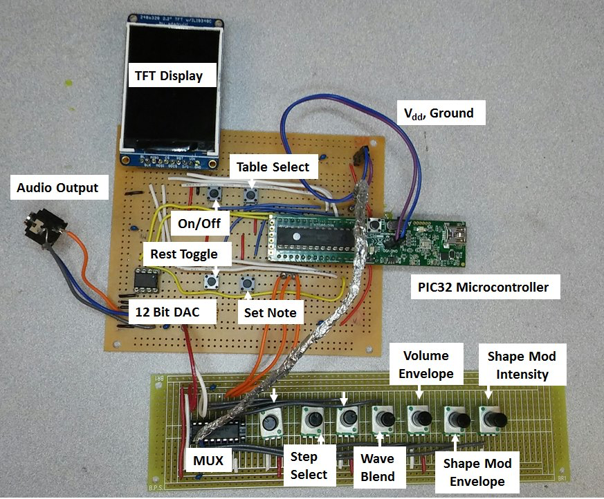
The hardware for the synthesizer is composed of a PIC32 microcontroller, 7 potentiometers, 4 buttons, an 8:1 analog multiplexer, a 12-bit DAC, and a TFT display. Using user input from the various potentiometers and buttons, the PIC then generates different sequences and waveforms based upon the current inputs.

A full hardware diagram can be found in the Schematics section.

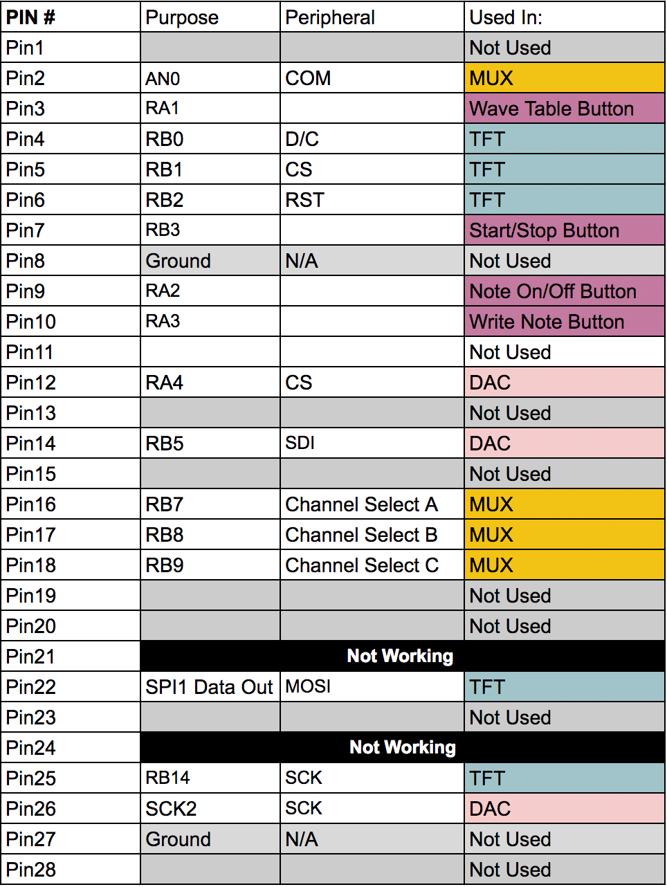
Our TFT display is connected the way it has been for the previous labs, using pins 4, 5, 6, 22, and 25.

Button/Knob Control Functions

controls

Pin Connections

connections
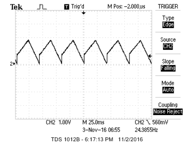
The PIC32 then used direct digital synthesis running at 100 kHz to generate the correct waveform specified by the input settings. The generation of the waveform required the use of an external 12-bit DAC, the MCP4822. The DAC has two output pins, VoutA and VoutB, of which we only use VoutA. VoutB is sent to ground, along with Vss, and the LDAC pins.

The DAC is responsible for the main deliverable portion of our project, so its function is quite visible. However, the other main bit of hardware in our setup is the CD4051B multiplexer, which takes input signals from all of our potentiometers and relieves pressure on the PIC32’s ADC capabilities. Most of the ADC pins on the PIC32 are taken up by the TFT display, and so only four pins exist for our 7 analog inputs. Clearly, even if we were to use all the ADC inputs, there would be a need for multiplexing, as there would be three knobs unconnected. If we were to use multiple ADC pins, then we would also have to re-configure the ADC setup in order to multiplex between all the ADC pins.

Under the hood, there exists only one ADC in the microcontroller, so it would be multiplexing between all of the ADC pins, in addition to the multiplexing we would be doing on each pin. The CD4051B perfectly addresses this issue, due to it having eight inputs, outputting a single signal which we could read on the one ADC pin on the PIC32. Thanks to the multiplexer, we can keep the existing ADC configuration. Although the multiplexer requires three extra channel inputs, which are controlled by the PIC32, we have plenty more options with it, seeing as they can be digital outputs. The multiplexer takes Vdd from the PIC32 power rail, and uses all the signal input pins except for Signal 5, which we grounded. The Vss, Vee, and INH pins were also sent to ground.

In order to stabilize the voltage output by the PIC32, we placed various 10µF capacitors between power and ground on the hardware. This smoothes out spikes and drops in the 3.3V output of the microcontroller.

Preexisting Code

All of the preexisting code we used was boilerplate code from the ECE 4760 course website for setting up ISRs, DACs, I/O pins, and timers. We also used the Protothreads library by Adam Dunkels, and the tft_master.c/tft_gfx.c libraries provided by Professor Land.

Roadblocks

The most vexing bottleneck in our project was getting the multiplexer to work properly. After wiring it up according to the data sheet, it would only function intermittently, working properly sometimes, and then being completely unresponsive at others. In addition to this, when the hardware did function, a few potentiometer inputs seemed to interact with others. Specifically, the first signal input would be altered slightly by every other knob, and the sixth knob would bleed into all other inputs. Since the multiplexer would work sporadically and unpredictably, it didn’t seem as if software was the issue, though it was possible. When touching and bending wires, we would occasionally be able to change the functionality of multiplexer, but these events would not affect the multiplexer consistently.

One possible explanation for this behavior takes into account the electric fields our bodies generate. Depending on where we would poke wires and our own orientation, the multiplexer signal wires could have been affected. This issue could be exacerbated by the fact that we had channel select wires crossing over the analog outputs of the multiplexer, which were both in close proximity to our power rails. This served as part of the motivation to move our hardware setup to perfboard. To further address the signal-to-noise issue, we placed capacitors between power and ground, and moved wires away from the TFT display. In case of internally broken wires, we also replaced all the signal wires connecting to the multiplexer. In order to address the possible internal signal bleeding of the multiplexer, we grounded pin 5 of the multiplexer, which equated to the 6th signal input, the multiplexer pins being 0-indexed.

After taking all the actions listed above, the multiplexer behaved more consistently, but we were unable to read from more than 2 different sources, beyond which we received garbage data. This issue this time was a software issue; we weren’t waiting long enough between switching index bits to read the ADC pin. The PIC’s DigitalRead settling time, internal ADC sampling speeds, and the multiplexer’s switching speed require dozens of processor cycles of waiting, so we put in a delay of approximately a microsecond before each read. The function for waiting 1µs included in the TFT library was not working for some reason, so this wait was achieved using a for loop with no body.

Carrying out these fixes largely took care of all the issues we were seeing. Because we implemented most of these methods in parallel, we were unable to isolate one particular root cause of the malfunctioning, but taken together, we would say that the issues were some combination of the challenges mentioned above.

Another issue that was present throughout much of the project was the random appearance of white dots on the TFT display. Over time after power-on, pixels that should have stayed black would become white.The code never called for white dots to be printed, so we couldn’t isolate the error. Our first fix to this problem was to write a segment of the screen black every 10 seconds. However, this was a purely aesthetic fix, which did not remove the underlying problem.

Eventually, we realized that putting our sequencer's active-step TFT updates in an ISR to achieve a constant, fast update at high tempos was the root of the problem. Since we had TFT updates in this ISR, and in a separate thread used to update more slowly- updating parts of the UI, there were many scheduling scenarios in which the serial data sent to the TFT was corrupted. In some instances, this conflict would cause the PIC32 to crash entirely. After realizing the origin of our problem, we moved all TFT updates to a single thread. This thread ran at 15-20 fps, and due to the less-frequent update, our sequencer's active-step readout could be jumpy at certain sequence speeds. However, we gained overall performance by eliminating this potentially fatal stress on the serial data bus.
TOP

Results

Wave Tables

We ended up using 4 wavetables in the final version of our project, each with 8 waves per table. These 4 tables aimed to help users achieve a wide variety of sounds. The tables, and images of their waveforms (labeled by index), are shown below:

Below are 4 audio clips of fades through each of the wavetables listed above. Each fade is performed on a note of frequency C3 (130.81Hz).


Speed and Responsiveness

Because of compromises we made to keep sample rate high, and relocation of TFT code, our TFT display, the main aspect of our user interface, was not necessarily as responsive as we would have liked. We updated the TFT display at a rate of 20Hz, which was in general undetectable by human perception, but because this frequency could often be too slow our out of phase with the sequencer step progression, the red highlight on the active step could sometimes seem jumpy, as it would transition to a subsequent step in slightly different time intervals to keep up with the sequence. We decided the degree to which this affected the user experience was minimal and excusable.

The multiplexer thread for reading in the 7 knobs was also run at approximately 20Hz, which could cause audible stepping on some controls, especially the wave blend control. Because 20Hz is essentially below most normal humans' ranges of hearing, turning the wave blend knob quickly would not sound like a smooth timbral morph, but instead jumps would be audible each time the multiplexer thread captured a new blend value. As stated above about the TFT display, this reading speed was a necessary compromise in order for our synthesizer to function.

Buttons were read in the button thread at a rate of approximately 10Hz. This helped with debouncing (although that was not the goal of this sample rate), but also caused some noticeable artifacts in the pressing of buttons. Sometimes, if a button was pressed too quickly, the thread would not capture the action at all. As a result, to ensure a buttons' associated software action would be taken, buttons had to be held down for a short period of time.

Accuracy

There were a few different aspects of our implementation that contributed to the accuracy of the tones and waveshapes we produced, both in terms of fundamental frequency, harmonic distortion from the original generated wavetables, and spurious harmonics i.e. aliasing. These factors were:


At a DDS ISR sample rate of 100kHz, our highest frequency, C5 (523.25Hz), would only have approximately 191 of its 512 samples played per cycle, a result which, because of the harmonic content in many of our waveforms, led to some aliasing. Had we bandlimited our wavetables using frequency-dependent resampling of the waves, we could have avoided much of this effect, as 100kHz should be a sampling rate high enough to represent all of these waveforms without aliasing as long as the appropriate measures are taken. We did not have the resources in our ISR to do this kind of dynamic resampling, nor the space in memory to do it statically, so we do have some aliasing in our output, especially at higher frequencies. This can be seen in the FFT of our sine wave at C5, which is shown below along with a couple other scope captures.

Sine Wave Shape on Oscilloscope

sine wave shape

Sine Wave FFT at C1 (32.70Hz)

sine wave FFT, C1

Sine Wave FFT at C5 (523.25Hz)

sine wave FFT, C5
As can be seen in the first of the three images above, the sine wave's shape is pristine, due to our high sample rate and high internal sample bit depth. The internal sample bit depth allows us to do all sorts of scaling operations on our waveforms, such as crossfading and amplitude enveloping, without losing any necessary information by the time we send the sample out to the 12-bit DAC.

The results of rounding our phase increments to their nearest integer representation (which was necessary to store them as unsigned integers) can be seen in the slight deviation between our output frequencies for C1 and C5 and their actual frequencies. In the 2nd image above, the sine wave at C1 appears to have a frequency of 32.66Hz instead of the actual frequency of 32.70Hz, with a total error of 0.12%. In the third image above, the sine wave at C5 appears to have a frequency of 522.56Hz instead of the actual frequency of 523.25Hz, with a total error of 0.13%. As can be seen from these calculations, our frequencies are very accurate to around 1 part in 1000.

Our signal-to-noise ratio (noise here includes spurious frequencies i.e. aliasing) was also very acceptable. In the FFT capture of our sine wave at C1 (2nd image above), there are no obvious aliasing frequencies among the garbage at the noise floor, but the signal-to-noise ratio is (as denoted by the cursors) approximately 54dB. In the FFT capture of our sine wave at C5 (3rd image above), there is a fairly obvious aliasing frequency sticking out above the rest of the noise floor, so we set our lower cursor there. At this frequency (albeit with our wave having the least harmonic content) we had around 46dB of difference between our fundamental and noise/aliasing. We found these results to be acceptible, and most of the time when using our synthesizer, any small aliasing effects are hardly noticeable.

Safety

When using this synthesizer, there aren’t any major safety considerations to take into account. The greatest danger is from the user to the board itself, as ESD can render the board unusable. Incorrect placement of the microcontroller on the pins can also result in blowing out some of the PIC32’s pins. Of course, one must take care as to not prick their fingers due to the solder points on the back of the board.

Usability

Our main usability issues could be solved if we had more time to develop our project into a polished product. One small, but annoying usability issue is the type of potentiometer we used. We mistakenly ordered potentiometers with center detents (the smooth turn of the potentiometer temporarily locks in place in the center), which is great for bipolar controls. Unfortunately, none of our controls are particularly bipolar, so this was more of a nuisance than anything. In a final version of the product we would, of course, use non-detended potentiometers.

It is also difficult to make small value changes on potentiometers with no knobs attached. Putting knobs on the shafts of all our potentiometers would make it much easier for users to dial in precise values and make very slow sweeps of parameters, improving the user experience of our synthesizer dramatically. Putting all of the circuitry inside an enclosure that the user could carry around without worrying about damage to the synthesizer would also help with usability, as it would be easier to take our synthesizer on the go to performances and the like.

Overall, our synthesizer still ends up being very usable, as is evidenced by the performance video embedded at the top of this webpage. One should listen to this video with headphones or earbuds to best enjoy the range of frequency content generated by the synthesizer.
TOP

Conclusion

Conformity to Initial Specification

Although our design certainly deviated somewhat from the original plan, the larger direction that the final design took mirrored our original vision. Below, one can see the original and final designs of our project.

Original Project Layout/Design

original layout

Final Project Layout/Design

final layout 
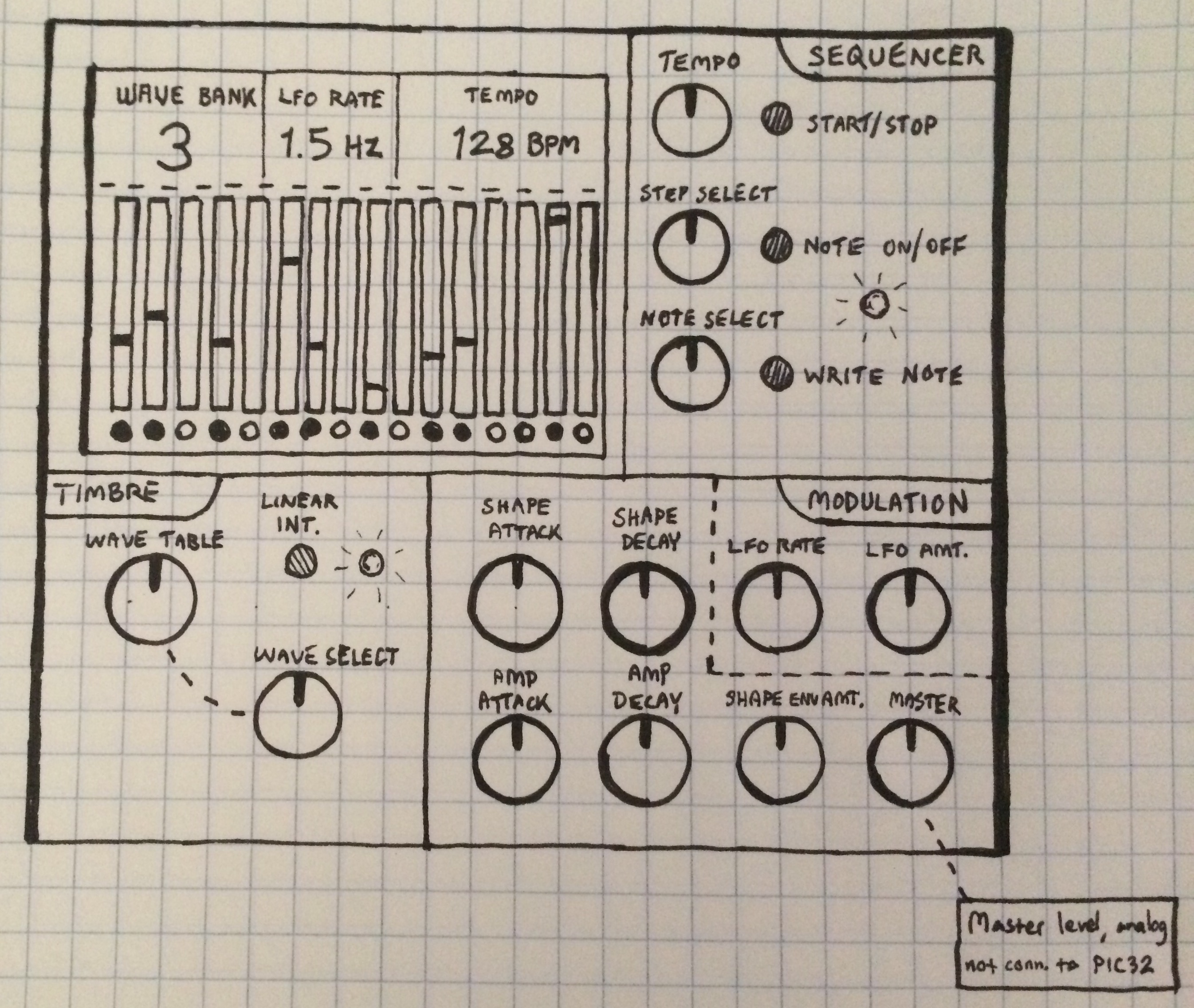
Some of the design changes between the intial and final designs were just logistic changes, such as the two perfboards in the final product rather than the initial projection of one large PCB behind a panel. The layout is a more messy in our final prototype, with the knobs and buttons unlabeled and ungrouped. We also cut back on a few different controls, both for usability and because of hardware limitations. The LFO and its intensity control was removed entirely. The amplitude and shape envelopes were cut back from two knobs each, for attack and decay, to one knob each, using a modal envelope scheme. This change allowed for most common attack/decay parameter combinations, but avoided a complicated control scheme and complicated ADC configuration.

Similarly to the knobs, the buttons were not grouped by function or labeled in our final design. The linear/stepped interpolation button was entirely removed from the final design, and a table toggle button took the place of the table select knob. The LEDs alongside the buttons were not included in the final project, as the information they provided was trivial/irrelevant and could be derived from the TFT display. The TFT display's layout was essentially identical to its original conception, although the LFO frequency was replaced by the name of the current note to be written.

Most of the modifications we made were mostly due to lack of time and resources, and given more time, we would probably structure our project to visually resemble the original design.

Future Ideas

During the implementation of our project, we started realizing that there were many possible expansions to this design. One of these is the length of are sequencer. Playing notes, or four measures, is not too difficult to implement, fits well on the TFT, and provides some flexibility in creating musical phrases. However, increasing this limitation from 16 to 32 would have unlocked countless new ideas; many video game and movie themes can be realized with 32 notes. In order to visualize this modification on the TFT, we could halve the width of each note's representation on the screen, or create two pages of notes, each of which would retain the clarity of the original 16-note page. Of course, a second page would add much more complexity to our codebase, something we didn't want to introduce to the project's scope.

Although we could change each note's frequency individually, our wave blending controls applied to the overall 16-step sequence. If we could set table index and blend values for each step, our sequence would be much more dynamic. Enabling this kind of customation would require an extra sequencer page, which could lead to a much more complex control scheme and more complex code bookkeeping in our TFT thread and elsewhere.

If we were to implement these ideas, we would benefit from restructuring the layout of the TFT screen. Displaying all the new information on the current screen could get too cluttered. One way to handle all the new information we would need to display would be to have different screen templates which would be rendered depending on the current 'mode' of the synthesizer. Some screen templates could be for viewing the different sequencer segments, while others would be for viewing overall program information such as envelope shapes, table index, and blend values. Another sequence programming feature we wanted to implement but didn't get around to was 'phantom notes'. When programming steps in our current implementation, only the note to be programmed is displayed. However, with 'phantom notes', a representation of where the new note bar would be in the sequencer step readout would appear, adding a more interactive element to note editing.

Another feature we would have liked to add is presets. This is the ability to save and later recall all parameters associated with a particular program, including its sequence data, into flash memory, to be recalled later even between power cycles. This would require another mode for the screen, as well as procedures to pack the program data together and save/recall it. We would also need to change the way our knobs functioned, as any recalled data, with our current knob reading thread, would be instantly overwritten with whatever values the knobs were at. We could use one of a couple different knob scaling schemes to make this work. One method would be a one in which, after a saved preset is loaded, internal value do not change until their associated knob goes past the value stored internally. The other method would be a curved method in which disagreements between knob positions and internal values would be scaled on an exponential curve.

Aside from our software, one shortcoming of our project was its presentation. Having exposed perf boards, hardware components, and the PIC32 looks somewhat unprofessional, and also increases the possibility of the user breaking parts of the project. While damage was less of an issue with us, the designers, handling the hardware, if we were to create a more polished version of the synth, we would fashion some sort of box to contain the whole system, possibly out of laser cut acrylic or wood, with the user inputs easily accessible and labelled. All pots would be bolted to the faceplate for stability, and each pot shaft would have a real knob on it to allow for finer tuning of parameters. An on/off switch would also exist on this box. This possible improved design would be much more professional and better looking as a product, and would reduce the chances of accidental damage to the circuitry.

Intellectual Property Considerations

We used a general synthesis concept, wavetable synthesis, that many digital synth designers have taken advantage of over the past few decades, which is also somewhat of an expansion from the simple tenets of DDS we learned in lecture. Since the only code we reused was code provided by the course staff, and did not reverse engineer a design but instead implemented a publicly available concept, we did not run into any intellectual property issues.

Ethical Considerations

This section is written in reference to the IEEE Code of Ethics .

The most important ethical issue that we faced in our project was the usage of the 3rd-party software to generate our wave tables. As mentioned earlier, the waveforms used in our synth sequencer were first generated using Xfer Records' Serum. The other programs we used were open source, and therefore free to use. Using pirated software would be against the spirit of the IEEE Code of Ethics, as would selling our synth using their ‘technology’. Since Ian's license of Serum had Xfer Records compensated and our project is not for profit, we avoid ethical violations.

In addition to stealing technology, we also could have harmed our fellow students by plagiarizing their ideas. Audio-related projects are fairly common, and it wouldn’t have been difficult to rip off similar ideas of our peers and claim them as our own. Needless to say, this would also be a serious breach of the code of ethics. Thankfully, our interest in finding our own implementation rendered cheating completely unnecessary. Although we use boilerplate code from the ECE 4760 page, that code was freely provided to us for use in previous labs, so there exists no conflict of interest on that front.

Legal Considerations

There are no legal considerations to take into account for this project.
TOP

Appendix A

The group approves this report for inclusion on the course website.

The group also approves the inclusion of this report's associated YouTube video on the course website. TOP

Commented Program Files

TOP

Schematics

Hardware/Circuit Diagram

circuit diagram TOP

Cost Details

Bill of Materials:


    Total cost: $35.23

TOP

Member Roles

Ian Hoffman (ijh6)


Joval Mathew (jjm448)


Balazs Szegletes (bas332)

TOP

References

TOP