Laser Display
Peter Friend, Istvan Burbank, James Cassell
Peter Friend, Istvan Burbank, James Cassell
An image projector that draws using colored lasers controlled by a PIC32.
Brief video demo, videography by Bruce Land.
Our goal was to make a projector that can display rasterized color images by casting lasers onto a screen. We use several colored lasers to generate a single pixel which we scanned across the screen using a system of mirrors. A vertical mirror controls the height of the projected laser. A spinning mirror assembly causes the laser to "scan" horizontally. We were able to achieve a projector which outputs small frames in 4-bit Red/Blue color space and have plans to continue development.
The horizontal-scanning mirrors are four mirrors on the sides of a spinning cube. A single row of the output display is shown in the time it takes for one of the four spinning mirrors to move through part of it's arc. Each rotation of the mirror assembly is thus four rows. The rotation of the mirror assembly is used to control the beginning of a row via a phototransistor and Change Notification interrupt. DMA outputs the entire row into our diode control circuits, with a timer controlling the time between pixels. The interrupt for the end of the DMA block transfer is used to configure the DMA and the vertical mirror for the next row.
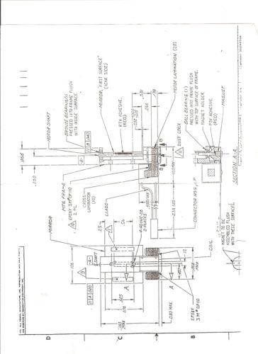
First item we wanted to determine was what range our angled mirror would need to support. To do this, we are able to find the max and minumum angle as a function of distance, height, and mirror size.

One concern that we had with using mirrors to scan rows, was the potential arcing of rows due to the different distances the laser has to travel to hit the mirror. By using the figure below, we can use some trigonometry to determine how big the arc will be at the largest point from the smallest point of the arc.

The pixel size of the display is directly tied to the beamwidth of the laser. Due to the nature of the lasers that we used in our setup, we did not observe many nonlinear effects in terms of beam divergance. Therefore when we measured how fast the beam diverged, we assumed that it diverged linearly. We describe beamwidth as a funciton of distance from the mirror. The pixel size that you are able to have, is the size of the beamwidth at a given distance, as we cannot have mulitple beams overlapping, causing aliasing of the output.
After finding the size of each pixel, it was important to determine how many pixels that we could display at a given speed of our mirror array. As seen in the figure below, the mirror array must turn by $$\theta = arctan{(beamwidth / D)}$$ to draw nonoverlapping pixels.

We made heavy use of the MCU peripherals and offloaded burdens of timing and control to hardware when possible. The rational was that the CPU would be heavily used by a game or other software creating the image to be projected. Additionally, triggering events based off of hardware allows use to be agnostic to changes in physical conditions and avoid synchronization bugs. For example, the start of each horizontal scan line is triggered by the position of the mirror carousel; if the mirrors are not running at a perfectly constant speed the impact on our system is negligible. Our use of DMA within the horizontal lines triggered by a hardware timer ensures even spacing of pixels regardless of the CPUs load or state.
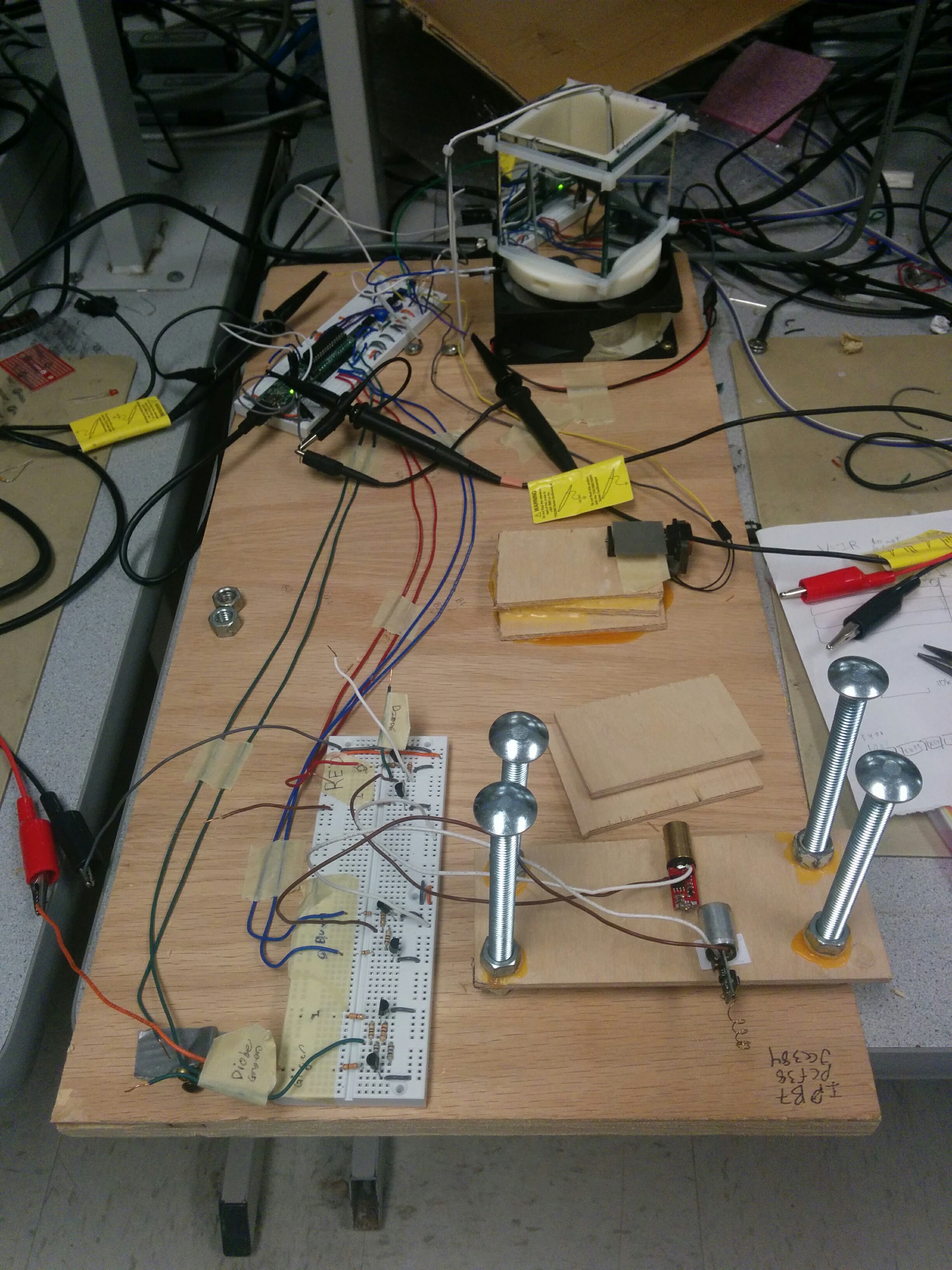
The horizontal mirrors are held on to a 3D-printed assembly with zipties and glue which is in tern affixed to a fan motor. The assembly has no top surface and is mostly hollow. The top part has four sides, each with a mirror attached on the outside. The bottom part is a disk with four slots cut in the sides that reach all the way into the hollow center allowing a LED inside to strobe a phototransistor on the outside.. Each slot is aligned with the middle of the face with a mirror attached. The angle of the mirrors to vertical is precisely calibrated by paper washers slipped behind the mirrors to push the top edge out (the bottom edge is glued). The assembly screwed to the plywood.
The emitter is hung at the bottom of the hollowed out interior of the mirror rotation assembly by a stiff wire screwed into the wood base. The phototransistor is similarly held on a wire just outside of the spinning mirror assembly. The precise position of the phototransistor is used to calibrate the horizontal position of the rows.
The Y-Axis mirror sits on a stack of wood glued down to the plywood. The mirror is attached to a galvanometer which sets the mirrors angle proportional to the current supplied. It is held down by tape temporarily so that the precise angle can be easily calibrated. The distance of the vertical mirror from the spinning mirror assembly partially determines the distance between rows, along with software tunable settings. The vertical mirror slightly deflects lasers vertically before they hit the spinning assembly, which deflects them side-to-side.
The laser platform is a piece of wood with nuts glued to it. Carriage bolts screwed through the nuts can be used to adjust the height and angle. The laser diodes are hot-glued down to the platform and hand-calibrated to shine at roughly the same point on the screen. Additional easily configurable software calibration can adjust for some physical calibration errors.
The laser control circuit consists of three adjustable current sources. Each laser has its own current source which is controlled by a two-bit color signal. The laser control circuits are standalone on a breadboard which is affixed to the plywood base near the Laser Platform.
To design the diode control circuit, each of the laser pens used in the display needed to be taken apart and understood. After tearing apart the laser and opening it up with a dremel, we found vastly different circuit designs on each of the different colored lasers. Though pleasingly enough, eac PCB was the same color as the laser.
The red laser has a PCB which is connected to the laser which has two leads on it. One of the leads was connected to the casing which serves as the voltage reference. The other lead is connected to the circuit on the PCB, which is shorted to ground (the spring on the end of the PCB) when a button is pressed. To test what the voltage drop was across the laser, we turned the laser on, and recorded the voltage at each of the leads to the laser. This is how we found out we had a voltage drop of 1.7V across the laser.
The process was very similiar with the green laser, the exception being that the green laser has three leads on it. But two of them were shorted together by a mountain of solder so we treated it as one point. With the green laser we found that there is also a 1.7V drop.
The blue laser in the set was the strangest of them all. Like the green laser, the blue one had three leads, but they were not shorted together. Instead one lead was connected to what looked like a small transformer on the PCB. The fact that when the laser was powered and we probed that lead which turned out to be at 6V appeared to confirm our suspisions. The lead next to the lead with the transformer, appeared to be connected to the PCB not involving the transformer, with the last lead being the voltage reference. After a bit of tinkering, we found that we could power the laser ourselves if we ignore the lead with the transformer, and connect 2.5V to the voltage reference and the last lead to ground. As such for the rest of it's use, that last lead is ignored.
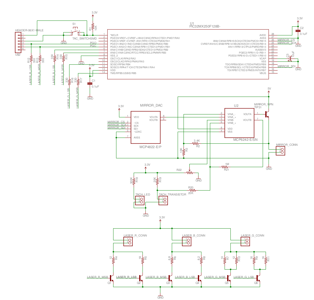
After finding out which leads on each of the lasers to connect power and ground to, we tested varying intensities of each laser. For each laser, we would increase or decrease the current across the laser using a desktop power supply, and recorded the amount of current for intensities we wanted to include in our display. There was not a large range of intensities that were easy to distinguish, so we went with 2-bit color for each laser. These 2-bits represented, off, low power, medium power, and full power. We soon found that the laser take much more current than the PIC32 is able to source (180mA-250mA for red and blue, 350-550mA for green). As such, we needed to design a current sink that the PIC32 could control. To do so, we have a current sink made with BJTs and a resistor. The resistor value was chosen based on the voltage drop across the laser and how much current we wanted. Each laser has two current sinks, one for low power, and one for medium power. When combined, they act as sinking the full power level. The BJTs' bases are conneceted to digital outputs on the PIC32, this allows the PIC32 to control the current supplied to each of the lasers digitally.
The mirror is affixed to a galvanometer, so we need to control the current applied to the mirror assembly. We determined that the mirror has a fairly constant and real impedance, so we use a variable voltage source. Based on the voltage, the mirror moves to a certain angle. Based on tests, since documentation is lacking, we found that its voltage range is from 0 to about 10.5 Volts. When mounted to our assembly and tested with a laser, we found we were able to strike the mirror array in the range 2.0V to about 5V across the terminals.
To control the amount of voltage across the mirror, we have the PIC32 control the output of an MCP4822 DAC over SPI. We defined parameters in the PIC32's programming such that it only tries to use the range at which we will hit the mirrors with the laser. The DAC is able to output voltages from 0-3.3V, but we needed a larger range for the mirror. This lead us to using a MCP6242 op-amp which gives us enough gain to have a range from 0-4.4V. The 4.4V does not give us the full range of the mirror, but as the mirror is quite large we still have the ability to scan many rows. The op-amp is unable to source enough current for the mirror though, as it sinks about 100mA. Therefore the op-amp is connected to a NPN power transistor's base which can easily supply enough current to the mirror, while also giving feedback to the op-amp so that we have the gain that we want.
Parts of the DAC circuit are supplied with 5V from a salvage power adapter. The fan is supplied with 12V from the same adapter. The diode control circuits are supplied with 3.3V from a bench power supply. All of the different power supplies were all tied to a common ground.
The rows to project are stored in a two-dimensional array of C structs. This struct uses bitfields, implementation-specific behavior, and a "bit packing" pragma to ensure that each struct fits in exactly a byte. Thus a single byte can be directly copied into the PORTB register to output the bits. This allows the DMA to transfer draw pixels without software intervention. An implementation-defined "struct punning" technique is used to convert these bit-packed structs into a numeric type when they must be written to the port without DMA.
Our projector implementation makes heavy use of hardware timing. That is, the projector code consists of several event-driven actions which are triggered by various hardware events.
DMA is used to output pixels to the lasers. When a horizontal scan line starts, DMA is configured to output the entire row, one pixel per period of timer A. Timer A is free running, and its period determines the aspect ratio of the pixels. The DMA transfer of the row is enabled by a Change Notification ISR which runs when the optical transistor is triggered. We configured the Change Notification via registers directly because our version of plib is missing the macros. Because this PIC32 cannot distinguish between rising and falling edges when triggering the Change Notification ISR, we simply check the value of the pin in software. Thus, effectively, the rising edge of the optical transistor triggers the start of a row being output. Because the optical transistor is driven by the spinning mirror carousel, the timing of the rows is too so spinning the carousel faster would result in faster output of rows.
When a row finishes the DMA triggers an interrupt that increments the Y-axis mirror's position. The reason it is done immediately at the end of a line is to ensure the mirror has time to settle into its new position before the start of the next row. The mirror is incremented linearly on each row until it reaches the bottom of the frame then it wraps around again to the top. Because the increment is triggered by the DMA which is triggered the spinning carousel, spinning the carousel faster would cause the Y-axis mirror's scan rate to increase.
The last two paragraphs made claims about the timing of the projector with respect to the carousel. In fact, spinning the carousel faster would increase the frame rate without any software changes. As the software stands now, the aspect ratio would change but that could be configured out (as the mirror spins faster the rows would get wider). The aspect ratio is determined by the period of the timer that triggers cell transfers in the DMA.
An earlier design attempted to use the gated mode of Timer1 to control the DMA and avoid the Change Notification ISR. The idea was that each timer period would start a cell transfer, but the timer would only run when a row had to be output. The edge caused by the phototransistor circuit was used to asynchronously set an external flip-flop high and the flip-flop output was used as the gate signal. The flip-flop would be asynchronously set low in the end of row ISR before the DMA was configured for the next row. This would have meant that an ISR was not required at the beginning of the row, only at the end. We abandoned this because the non-obvious but documented behavior of gated timers is to generate an interrupt when the gate input goes low and deactivates the timer, rather than on period match. This caused the DMA cell transfers to never fire.
We ported the TFT drawing library to be backed by our framebuffer rather than by the TFT. Due to the simplicity of the framebuffer interface, only rendering_drawPixel in the ported library had to be aware of the framebuffer. However, a number of functions in the interface to the original TFT library were written in a way that was tied to the TFT hardware, presumably for efficiency reasons. We rewrote these functions in terms of rendering_drawPixel to minimize dependence between the projector and the rendering library. This payed off when slightly changing the projector interface midway through the project required minimal changes to the rendering library. Additionally, the color representation of the original TFT library had to be replaced with our color struct, requiring very minor changes throughout the entire library. We added morse code drawing functions to the rendering library as a demonstration. All of the graphics in the demo are drawn using this library.
We mostly completed a port of the simulation, animation, and game logic parts of our Lab 3 Firehose game implementation. This involved using the new rendering API instead of the original TFT graphics API, and using new types for color and position. Additionally, due to bizarre limitations of Protothreads, we needed to strip it from the Lab3 code. The removal of Protothreads actually allowed a considerable simplification because we never made use of the more advanced synchronization features. The trimpot was to be replaced by a analog joystick, chose for generality. We wrote a joystick library using the ADC, but it became irrelevant in the limited final form of the project. Due to the unexpected limitations of the display, we never had a chance to test this port.
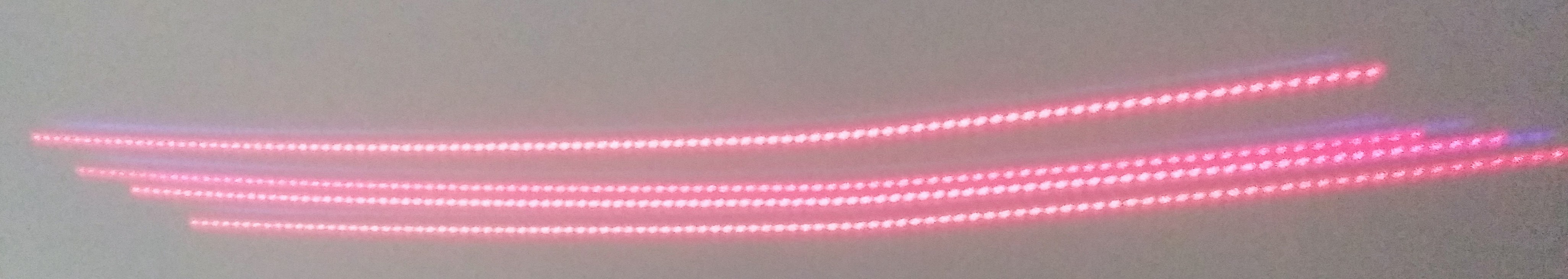
We started the project unsure if we would be able to achieve nothing or full VGA resolution projection. When we demoed the project we were able to display very crude 7x200 pixel frames with the red and blue lasers each with four different intensities (pictured above). In the next three sections we discuss what we were able to achieve more specifically in terms of quantitative results, safety, and usability.
The projector operates sufficiently to display up to ten rows at 10 FPS, and we have tested up to 200 columns successfully. We are able to project red and blue with variable intensities. Below is a brief analysis of the performance of each component of the projector.
The mirror carousel is a 3D printed cube with four mirrors attached to it, and that spins at over 1000 RPM. The limiting factor on our design was the mirror carousel. The timing of the whole projection system is based on the period of the mirrors spinning; if the mirrors spin faster then the FPS increases. Our mirror assembly is quite large, powered by a weak motor, and is not perfectly aligned. The result is that the mirrors spin slowly (at just over 1000 RPM), causing low FPS, and are off center causing the scan lines to be slightly unevenly spaced. The carousel spins at approximately 1200 RPM with is effectively 4800 RPM due to the four mirrors. If we were to drop in a faster effective carousel then the framerate would increase with no additional changes and would give us more headroom to project more rows.
The Y-axis mirror performs very well. The mirror is commanded to a new position at the end of each row and by visual inspection of the next projected row we can demonstrate that the mirror has settled by the time the next row starts. The mirror's position is precisely control-able allowing us to fine tune the spacing between rows. The galvanometer to which the mirror is attached draws 800 mAmps during normal operating (having a50 Ohm real component to its impedance). The high current draw necessitated a large amplifier which also serves to quickly control the voltage to the mirror. In total, the mirror setup is relatively simple and very effective.
The lasers and supporting circuitry successfully provide four-intensity control over red and blue lasers. The green laser circuitry is functional but we did not have a green laser which with to demo. The lasers are able switch on and off fast enough to project reasonably sized pixels and can produce sufficient intensities.
In total, the system functions acceptably well with a few clear and solvable bottlenecks which we plan to address in the future.
The use of lasers and the exposed, spinning mirror carousel are the primary concerns in terms of safety. To help control the dangerous regions where the lasers may be shining we employed cardboard guarding and operated in an unoccupied part of the room. After sufficient testing and tuning we were able to decrease the region in which the lasers would likely shine making safe operation easier. The spinning mirror carousel, operating at over 1000 RPM and with sharp corners, proved a minor hazard and one with was easy to identify (it is both noisy and visually easy to determine to be spinning) and easy to avoid. Overall, the risk when using the projector is minimal with trivial effort to avoid hazards.
We will comment on two types of usability: the usability from perspective of controlling what is projected and from the perspective of operating the device. We ported the tft drawing library used earlier in the class to our projector meaning it is not difficult for someone with training comparable to students received in the class to use the projector from a projection perspective. Currently, the program needs to be compiled and written to the microcontroller before use which proves to be a barrier for some users as compared to a VGA or HDMI connection. The usability of the device presupposing the software has been prepared and loaded is relatively trivial: there are three sources of power that need to be connected (power over usb, an inverter that plugs into the wall, and a 3.3V bench top supply). Besides powering the device there is occasionally a need to calibrate the position of the lasers, but that is rare.
The device as it stands is clearly a prototype. A better packaged model would eliminate these needs and simplify operation to a single power connection and a standard interface to control the projection. We plan to make such modifications on our own and as part of future classes.
Our expectation was to have a display resolution of about 50 by 50 pixels and a framerate around 15fps. This turned out to be very unrealistic. As was previously mentioned, the main limitation comes from the speed of the fan. The fan ran around 3000RPM without load, and we based our framerate expectations on the assumption that it would be running that fast in our project. The pixels of a row can be clocked out extremely fast because the only limitation is timer and DMA speed. However, the time between rows is limited by the fan speed, thus the framerate is limited. We also had a stretch goal of supporting some standard video input connections which proved to be too complex and given the resolution we are able to support impractical.
All of that said, we were able to demonstrate a nontrivial projection system and implemented it in a way that enables future development and improvement. We were able to achieve our main goals in the project and resolving some bottlenecks will automatically enable and enhance existing components making the system more practical.
Our C code complies with something in-between C89 and C99. We comply with airplane safety rules by always running the system inside and never pointing the projection at a window.
Our spinning carousel is loosely based off spinning carousel designs linked in the references appendix. However, our design differs substantially in how vertical positions are controlled; The designs linked use one mirror per horizontal scan line and adjust the angle of each mirror to achieve distinct scan lines without a Y-axis control like we have. We consider our use of a second stage an improvement as it will enable us to achieve arbitrarily many scan lines which in practical use would exceed the reasonable capabilities of a system requiring one mirror per row.
Due to the eye injury potential of the lasers combined with the unpredictability of the laser direction caused by moving mirrors, constant precautions were necessary. We never left lasers on when we were not actively testing, and we tested with the mirrors stationary as much as possible. We placed a cardboard shield behind the mirror carousel to prevent lasers that missed from shining across the room. We deliberately did much of our development in the end of the room to limit how far through the room the lasers would shine. We also explicitly told people around us that we would be running lasers not-too-far from eye level, consisent with the disclosure requirement in point one of the IEEE Code of Ethics.
The appearance of unexpected analog circuit design problems caused us to seek guidance both inside and outside the course staff. We track these contributions and attribute them in this document. Tracking copyrights and the preserving the copyright notification on the original TFT library in our derivative port is not only required by law, but required for compliance with point seven of the IEEE code of ethics.
Finally, we applied point three of the IEEE Code of Ethics in our performance estimates near the beginning of the project. Our framerate and image dimensions expectations were based on our limited knowledge of the limits of the analog circuitry and the memory limitations of the PIC32.
The group approves this report for inclusion on the course website.
The group approves the video for inclusion on the course youtube channel.
Check out our Doxygen Documentation
Also check out our GitHub Code repository where you can find our open source code.
| Name/Part Number | Price | Quantity | Vendor |
|---|---|---|---|
| PIC32MX250F128B | $5.00 | 1 | Bruce Land |
| Mircrostick II | $10.00 | 1 | Bruce Land |
| Whiteboard | $6.00 | 2 | Bruce Land |
| Bench power supply | $5.00 | 1 | Bruce Land |
| Jumper cables | $0.10 | 2 | Bruce Land |
| Laser Pens | $6.99 | 1 | http://www.ebay.com/itm/201641431339 |
| Y-axis Mirror | $6.50 | 1 | http://www.ebay.com/itm/380171994697 |
| Resistors | $0.10 | 21 | Lab |
| MCP4822 | $3.00 | 1 | Digikey |
| MCP6242 | $0.36 | 2 | Digikey |
| Trimpot | $0.78 | 1 | Digikey |
| LTE4208 | $0.54 | 1 | Digikey |
| LTR4206 | $0.43 | 1 | Digikey |
| 3D Printed Carsousel | $0.0 | 1 | Cornell RPL |
| Pack of 3 Inch Mirrors | $5.97 | 1 | Amazon |
| Total: | $58.87 |
| Salvaged Parts |
|---|
| CPU fan |
| Various pieces of wood |
| Carriage bolts x4 |
| Nuts for Carriage Bolts x8 |
| Coat Hanger |
