TALKING MULTIMETER

A CORNELL UNIVERSITY ECE 4760 FINAL PROJECT

BY RACHEL DIPIRRO (rdd49) AND JONATHAN LO (hl887)

A multimeter that reads the measurement for you

The talking multimeter uses the PIC32MX250F128B as a voltmeter, ohmeter, and capacitance meter that speaks the reading as it is measured. Spoken measurements improve the usability of measurement devices since the user will be able to focus on the circuit in question and still obtain measurements. The speaking measurement system will provides an auditory alternative to a visual meter. Our system consists of a TFT LCD to display the reading, a keypad to read user input about the mode of the system, and speakers to hear the readings of both the keypad and the measurements. Key presses on the keyboard determine if the multimeter is used a voltmeter, an ohmeter, or a capacitance meter. Additional circuitry and the functionality on the PIC32MX250F128B is used to map the voltages to ranges acceptable for the MCU and to calculate the parameter values. Capacitance values can be measured between 1pF and 100nF. Resistance values can be measured between 0 and 50kΩ. Voltage values can be measured up to 10V and mapped down appropriately for the MCU using a voltage divider.

High Level Design Overview

Here are all the things about our project

Rationale and sources of project idea

The talking multimeter improves the usability and safety of voltage, resistance, and capacitance measurements. By having the measurement spoken aloud, a user does not need to multitask while accessing nodes on the circuit. The device also provides a unique function for those with visual impairments. The measurement does not have to be read off of a screen, and the simple keyboard input reduces the amount of effort required to take the reading.

The talking multimeter project also incorporates many of the PIC32 functionalities we explored in the ECE 4760 Microcontrollers labs. This project implements the direct digital synthesis used in lab 2 DTMF dialer with speech feedback as well as the keypad functionality. Lab 1 implemented a capacitance meter; however, we use a different method to measure the capacitance in this project. The TFT LCD was used throughout the semester. With the knowledge from the past projects and support from Bruce Land, we decided that this project was an interesting and feasible final project.

Background math

The measurement system used the charge time measurement unit (CTMU) functionality of the PIC32 to measure the resistance, voltage, and capacitance. The CTMU is a programmable current source that can be set by the user and is directly connected to the ADC. It provided a fairly constant reference for all the measurements. The CTMU is enabled on an analog pin, so by taking the analog voltage reading and using the set current, we were able to calculate all the parameters of interest. The voltage measurement is a scaled version of the analog voltage based on the voltage divider on the input that protects the pin on the PIC32. The resistance measurement is the analog voltage reading over the current set by the CTMU, as prescribed by Ohm’s law. The capacitance measurement is the charge, found by discharging the CTMU pin using the built-in macros, over the analog voltage. The math behind the measurement was straightforward, given that all the data could be collected on the CTMU; however, calibrating the CTMU caused more trouble than anticipated. Our methods of calibration will be discussed later.

Logical structure

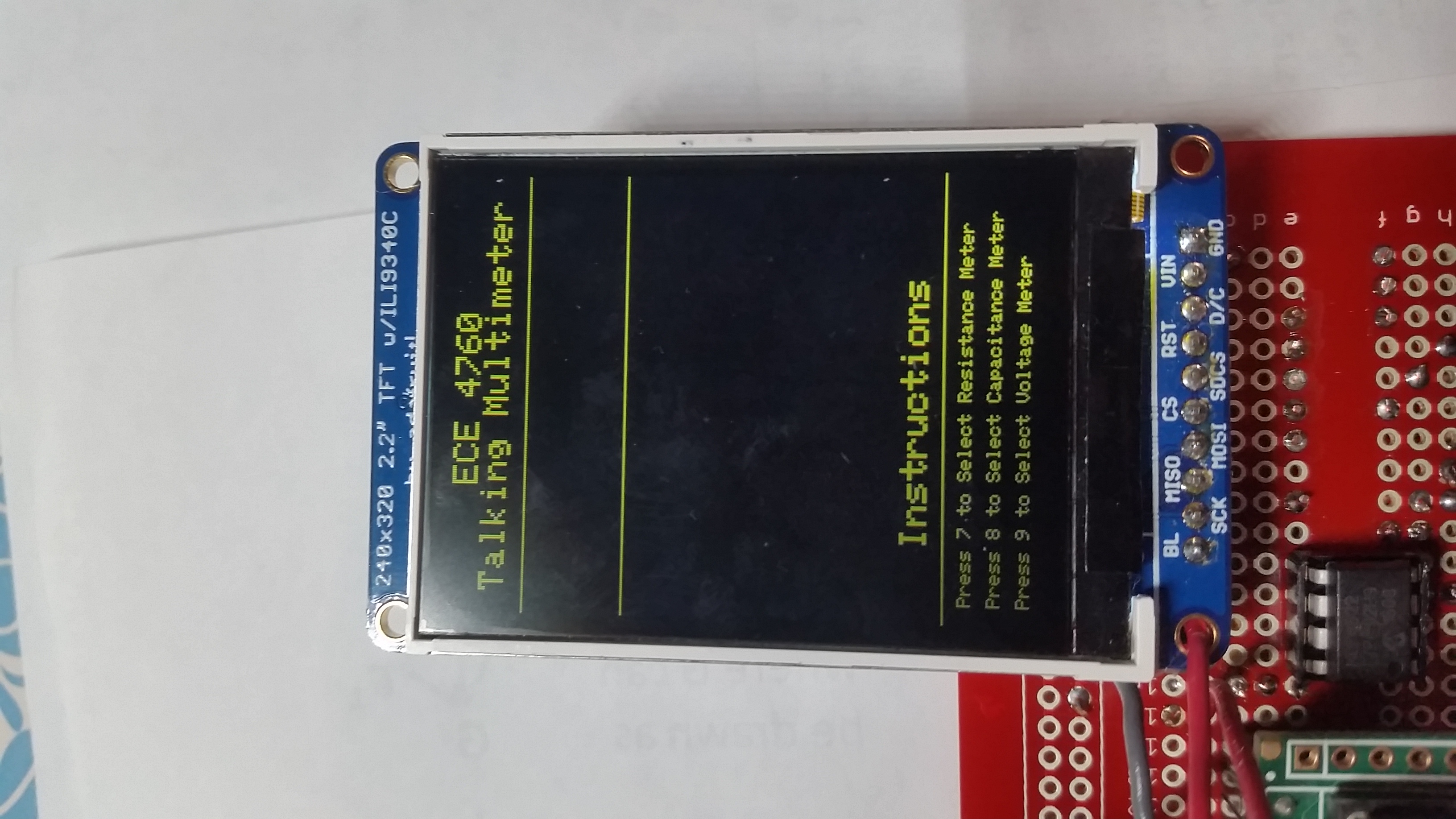
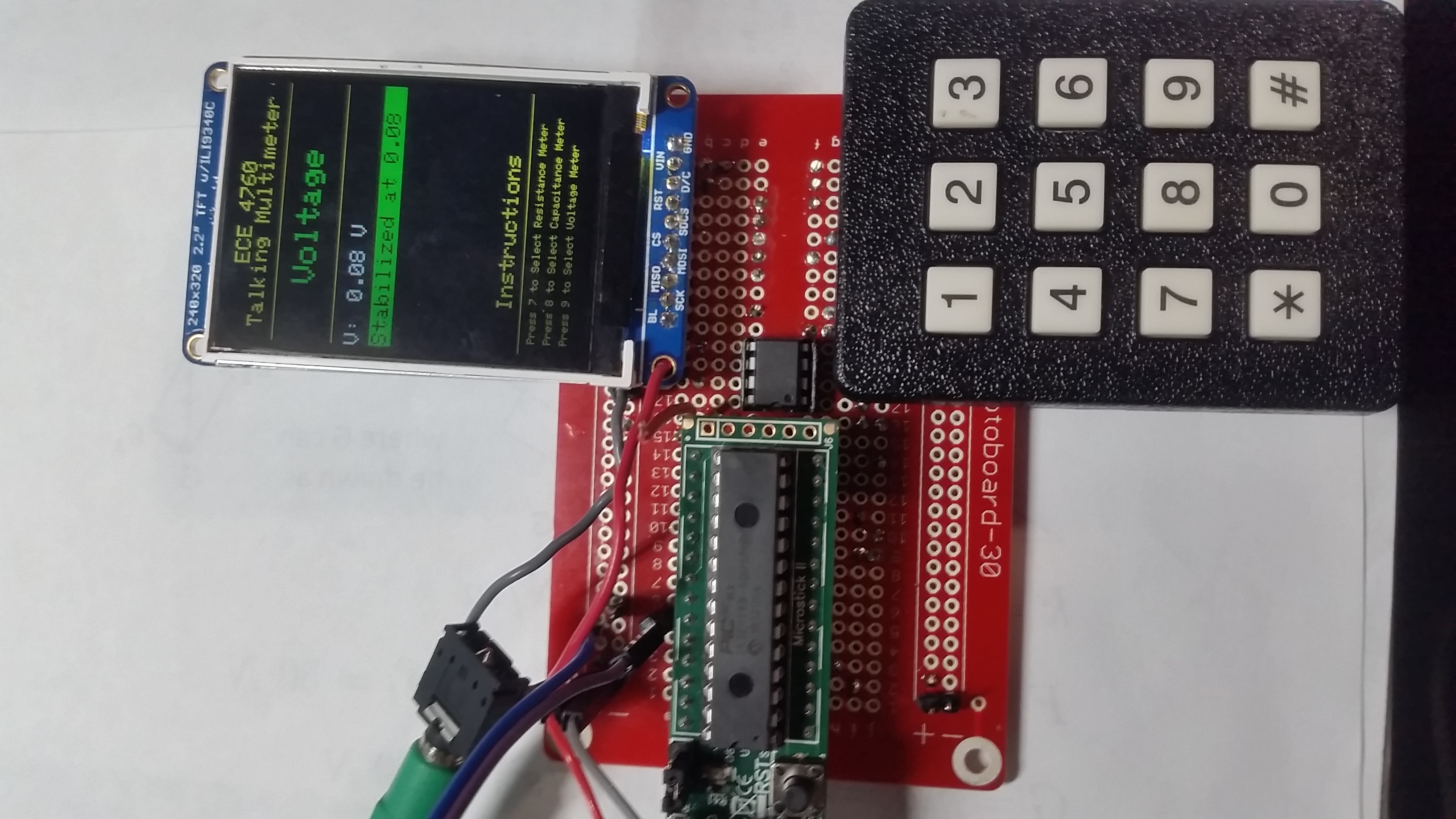
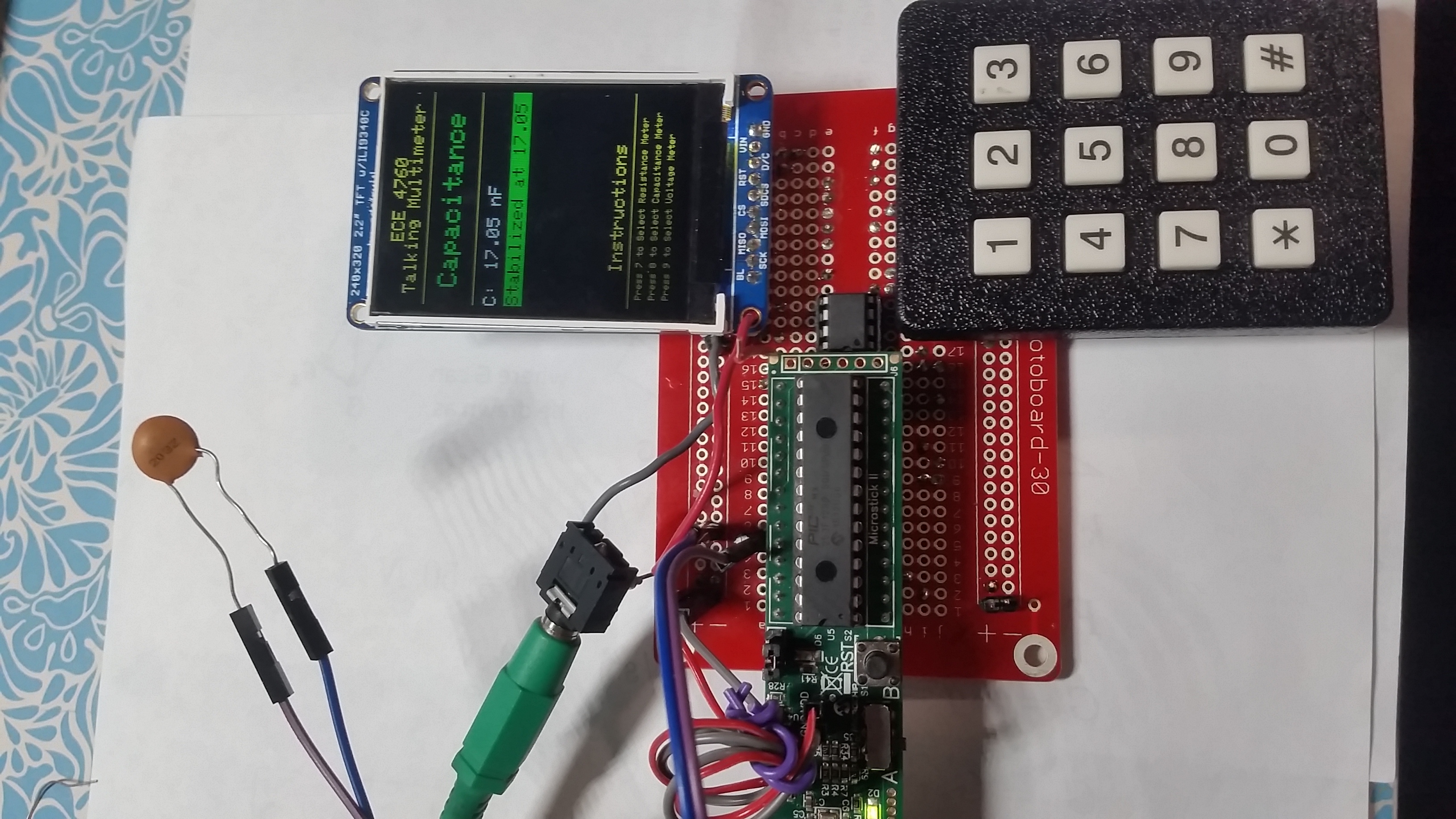
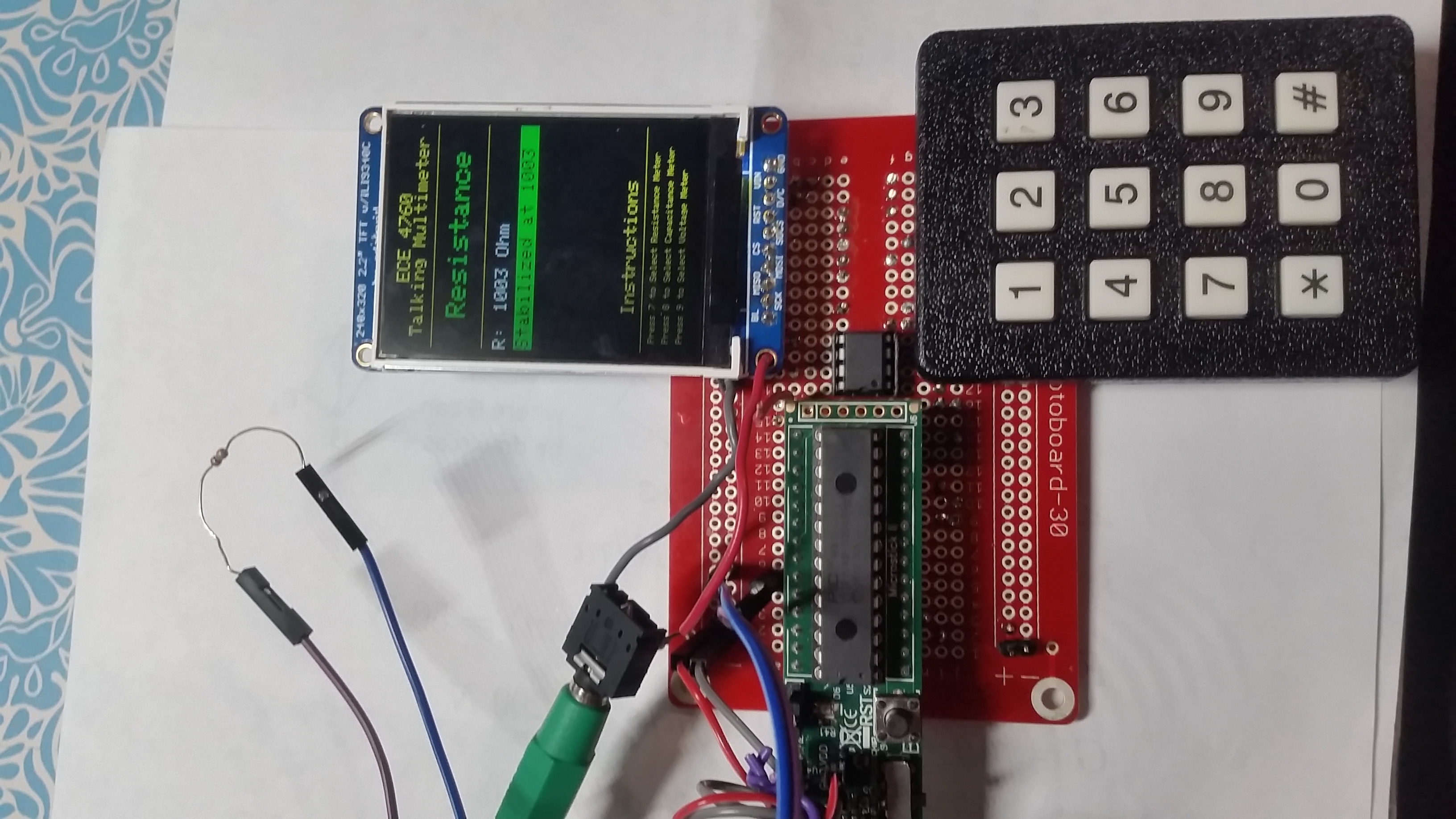
Our goal was to design a robust yet user-friendly measurement system, and we chose to structure our logic as a state machine controlled by button presses. When the system boots, the UI instructs the user to press the 7 key for resistance, press the 8 key for capacitance, or press the 9 key for voltage. Once the number key corresponding to the correct mode has been pressed, the user is prompted to confirm the selection by pressing the # key. The measurement is then read and stabilized after a given reading is detected for a certain amount of time. Once the measurement is stabilized, it is read aloud. Another number can be pressed to change the mode of the measurement device, or the # key can be pressed to take another reading in the same mode. We plan to improve this logic so that the stabilization resets on changes, rather than requiring user interaction. Pictures of the UI and the different measurement modes can be seen throughout the website.

Hardware/software tradeoffs

Hardware was an expensive but necessary component of our project as it provided the UI for the system. The design of the display, the keypad logic, and the calculation of the measurement is all done in software. The DDS is done in an ISR and pushed to an external SPI DAC. Using the external SPI DAC allowed us to utilize our implementation of lab 2 directly for this project. A future improvement would be using DMA to initialize the voice, which would greatly improve the speed of the system.

The main drawback of using the CTMU on the PIC32 was that it was fairly inaccurate with up to 20% error, and there was little we could do in hardware to improve this inaccuracy. Additional calibration was done in software to alleviate the large margin of error caused by the CTMU, but having a more accurate measurement system in hardware would have improved the efficiency of the system.

Standards

The talking multimeter meets the required safety standards for measurement as specified by the IEC61010 categories. The low-voltage electronic device falls under measurement category I (CAT I). The device is labeled as CAT I, and the 10V maximum voltage is provided. The allowable measurement ranges are explicitly defined, and resistors are used to prevent damage to the equipment.

Existing patent

There is an existing patent application for “speech synthesis and voice recognition in metrologic equipment,” publication number US20100070273 A1. The published device can measure voltage, current, resistance, continuity, frequency, and capacitance. It receives a voice command via wireless protocol to select the function, calculates the measurement, and reads out the synthesized speech through a speaker.

Software Design

Main Setup

For our main setup, we first set the PIC32 to run at its typical 40 MHz frequency. System wide interrupts are also set up for speech production purposes which will be explained in the following section. Since we are using an external Digital-to-Analog Converter (DAC) for speech creation, a SPI channel is also opened here. Afterwards, we set up our TFT display to show the basic user interface of our speech multimeter. It contains a brief introduction of the system at the top portion, meter measurements in the middle, and instructions at the bottom. See figure X. Finally, we initialize and put all of our protothreads within a while(1).

Protothreads

Speech Control Thread

Our first thread is a speech control thread. When a user selects a mode (voltmeter, capacitance meter, or ohmmeter), our system will first speak out the mode it is in. For example, when voltmeter has been selected and confirmed, a flag called rSpeechMode will be toggled, which in turn toggles our playFlag, which finally informs our ISR that the word “Voltage” is ready to be pronounced. The same goes for capacitance and resistance mode. In addition to speaking the mode that our user is in, the system also pronounces the measured value and its units. For example, a 5400Ω resistance measurement would be pronounced “Five-Four-Zero-Zero-Ohms”. In addition to pronouncing the value and unit depending on the mode we are in (rMode, cMode, or vMode), we have a stableFlag, a stabilization flag which we will talk about in the next protothread, and most importantly, two variables called digitLength and digitVar. digitLength measures the amount of digits for the stabilized value, while digitVar indicates the nth digit of a value. As we can see below, playFlag is only toggled once a second, and when the value hasn’t finished speaking yet. endFlag is toggled when the both the value is done speaking, and when the system is done pronouncing the mode that it is in. The reason we chose to have a separate thread that executes this every 1 second, is because this gives us control over the speed of our speech generation. By altering PT_YIELD, we can control the gap between each digit pronounced, and we came to the conclusion that approximately 1 second is the optimal audio

PT_YIELD_TIME_msec(1000) ;
 
if (rMode){
  // Stop at digit+unit, good for R mode
  if ((stableFlag) && (digitLength>=digitVar)){    
      playFlag = 1;
  }
  if (digitLength<digitVar+1 && !rSpeechMode)    endFlag = 1;
}
 
if (cMode){
  // Stop at digit+unit+2 decimal places, good for C mode
    if ((stableFlag) && (digitLength+3>=digitVar)){   
       playFlag = 1;
    }
    if (digitLength+3<digitVar+1 && !cSpeechMode)  endFlag = 1;
}
 
if (vMode){
  // Stop at digit+unit+2 decimal places, good for V mode
  if ((stableFlag) && (digitLength+3>=digitVar)){    
      playFlag = 1;
  }
  if (digitLength+3<digitVar+1 && !vSpeechMode)   endFlag = 1;
}
 
if(rSpeechMode || cSpeechMode || vSpeechMode) playFlag = 1;

Charge Time Measurement Unit (CTMU) Thread

Our CTMU thread is the heart of our talking multimeter. The CTMU thread performs all measurements, and is split into 3 different parts: Ohmmeter Mode (rMode), Capacitance Meter Mode (cMode), and Voltmeter Mode (vMode). CTMU was introduced to us by Professor Bruce Land. It is described as “a settable current source, with flexible triggering, and a direct connection to the ADC for measuring voltage”. Most impressively, it can generate pulse trains not synchronized to the CPU clock, and can therefore be used for resistance, capacitance, and even inductance measurements. For this part of our code, we utilized examples from the ECE 4760 CTMU page[2].

For rMode, a resistor was connected an analog input at pin 25 on the PDIP package, and ground. Since the current source connects directly to the ADC multiplexer that drives the analog input pin, the voltage read by the ADC scales accordingly with the resistance. We first set the CTMUCONbits.IRNG bit field to 2, which represents 5.5 microamps. This value was chosen for its immense accuracy from 1k-50k ohms. We explored the use of trims bit for fine current adjustments, but eventually did not pursue that attempt due to high accuracies that can be achieved from the available currents: 550, 0.55, 5.5, 55 microamps. As a full procedure, we first drain the circuit by setting CTMUCONbits.IDISSEN = 0, then we begin charging the current using CTMUCONbits.EDG1STAT = 1. Next, we OpenADC using specific parameters for resistance measurement, and set to current to 2. After we acquire the ADC , we simply wait for the ADC conversion, and read the results of channel AN11 from the idle buffer. Finally, according to the CTMU page, we calculated resistance using the following equation.

R = (float)(raw_adc-adc_zero[setCurrent])/ADC_max * Vdd / I_set ;

In order to calibrate our measurement, we obtained several resistors (about 10) of different values. We first measure each of those individual resistors’ true value using a reliable ohmmeter, then recorded that in an Excel spreadsheet. Next, we measured using our CTMU approach, and recorded those value in an Excel spreadsheet. By doing a comparison and a linear estimation of the two sets of data, we achieved an equation that allows us to measure values accurately, which will be discussed in the results section. Although a better option would be to implement autoranging, we unfortunately did not have enough time. This idea will be mentioned in our future improvements section.

For cMode, a capacitor was connected to the same analog input at pin 25 on the PDIP package, and ground. The steps of measuring capacitance are as follows: [3] First, we had to set the ADC with capacitance specific parameters. We then sample the ADC using AcquireADC10( ), then we use the CTMU’s internal discharge switch to short charge to ground from all the capacitance, which is absolutely crucial. We then pause the thread for approximately one millisecond. When the CTMU discharge switch is opened, the CTMU internal charge switch is closed using CTMUCONbits.EDG1STAT = 1. In order for the charge  to accumulate on the capacitor under test, we wait for at least 2 microseconds. The CTMU’s internal charge switch is then opened using CTMUCONbits.ED1STAT = 0 to stop charging. By converting the ADC using covertADC10( ), we can now read the ADC using ReadADC10(0) to get the raw ADC conversion. Finally, according to the CTMU page, we calculated capacitance using the following equation:

C = (Set_current) * (current_time_interval) / ((float)(raw_adc)/ADC_max * Vref)

Since measurements for capacitance were quite accurate, calibrations were not performed. However, the currents available from the CTMU does put a limit on the range of capacitances we could measure, going from as low as a couple hundred picofarads up to almost 100 microfarads.

For vMode, there were a few things to keep in mind. The analog pin has a maximum input of 3.3V volts. Our measurement range - designed to be from 0V - 10V, was made possible by doing a voltage divider as mentioned in our hardware section. This certainly gives us very simple and straightforward measurements, but required the most calibration. Since autoranging for the voltmeter is not too applicable in this situation, our best option was the Excel equation method mentioned above. Upon calibration, the optimal equation we obtained was:

V = (float)(raw_adc+3.5714)/107.89 + 0.05;

Finally, we will talk about how each of the three modes - rMode, cMode, and vMode, the measured value is turned into speech. Within each mode, we have an if statement that checks the length of our digit. This length is then stored into variable digitLength for safeguarding, then we create several arrays (ohmBuffer[20], capBuffer[20], voltBuffer[20]), where each element in each array stores the corresponding digit of the measured value. Using the following for loop, each digit will be stored in the correct order using division and modulation. Finally, we manually enter the speech elements for “dot”, and the corresponding units to the lenth, len+1st, or len+2nd element.

for(k=tempvalR;len--; k=(int)(k/10)) ohmBuffer[len] = (k%10);

One of the most challenging parts of this part is that it would cause the PIC to reset every time a reading is very small. We had spent hours trying to debug this issue, and it turns out that it was the flaw of using a float value less than one as an integer for decrementing in the loop. In order to fix that, we came up with several methods. For capacitance, which is guaranteed to be quite a small value, we first convert it into the nanos region, which takes us out of the <1 decimal zone. Next, we multiply the decimal parts by 100 to obtain the 2 decimal values we’d like to pronounce. Finally, we do the following to assign the first decimal, second decimal, and third decimal to our speech array.

Key Thread

Our key thread is quite similar to that of Lab 2 and Lab 3. For this project, our keypad serves several purposes - mode selection, and measurement stabilization. First let’s discuss mode selection. In order to select either ohmmeter mode, capacitance meter mode, or voltmeter mode, the user would first have to press a button. If the 7 key is pressed, a flag called resConfirm will be raised. If resConfirme flag is raised, the user will be prompted to press the # key for confirmation. This design was implemented so that the user wouldn’t accidentally select the incorrect mode. Not only would that be inconvenient, it could also physically harm our device. Once a mode is selected, we toggle our respective SpeechMode flag, which then prompts the device to speak out which mode it is in. If it is in resistance mode, it will turn off all flags not related to resistance, and reset all stabilization and counting variables for speech creation. After the mode is spoken, the thread then goes into stabilization mode.

Stabilization mode was in fact inspired by a digital scale one of our teammates used to own. Whenever we step onto a digital scale, we see our body weight ramp up, up to a value that eventually stabilizes and pauses, and the scale makes a “beep” tone that indicates this is your final weight. Similar to that, our measurements fluctuate. This is particularly challenging because if the measurement is fluctuating, the system may continuously speak out the same value over and over again but with a difference of a decimal value. In order to tackle this issue, we store our measurement value into an old variable for comparison. Every time a new measurement arrives, it is compared with the old value. If the two values equate, a counter increments. Otherwise, the counter resets back to 0. Once the counter has counted up to a certain amount, we determine the value is finally stable, and we toggle a stable flag, which is checked before the system performs any kind of SPI transmission to the DAC for speech production.

We learned that this kind of fluctuation can in fact be avoidable. Professor Bruce Land has suspected that the fluctuation is caused by the LSB of the ADC’s measurement, causing fluctuations as little as a millivolt. In fact, the LSB of the ADC is often most susceptible to noise, therefore it would be wise to take into account of this issue for a future build.

Voice Thread

Our final thread is where we assign the indexes for our digits, units, and miscellaneous words for the modes. First, we obtained the voice for digits of 0-9 from lab 2. It is a single-channel 16 kHz sample created from a now defunct AT&T text-to-voice site. This wave file was then processed with a MATLAB program to adjust the sample rate, truncate the PCM values to 4-bits, then pack two four bit samples into each byte for storage efficiency. This MATLAB program produces a header file of the packed samples formatted and is then loaded into flash memory. In addition to the digits, we used a free wav creation software “Text to WAV” and created speech for words such as “Ohms”, “Nanofarads”, “Volts”, “Resistance”, “Voltage”, “Capacitance”, “Dot”, etc. These were all appended after the digits provided in lab 2, and then fed into the MATLAB program by Professor Bruce Land [4] into a header file. The thread then carefully assigns the begin_index and end_index for each word.

//====Set voice and test mode=====================================
switch(desiredKey){
// The following are indexes for the digits.
  case 0:
     reset_voice = 1;    // Only toggle when a digit is to be pronounced.
     begin_index = 0;
     end_index = 2400;
     showKey_pressed = 0;
     break;
   case 1:
     reset_voice = 1;
     begin_index = 2461;
     end_index = 3787;
     showKey_pressed = 1;
     break;

Interrupt Service Routine (ISR)

Our ISR is one of the most important components of this project. It also caused the most issues, and required the most time to debug. Triggered by our system timer, the ISR constantly checks if playFlag has been set. If it has, it loads voice elements into an array depending on the digit or word that is to be spoken. Then, it transmits data to our external DAC for speech creation. We had discovered one weird phenomenon during our design. If the data is written to the DAC too quickly, voices sound corrupt and sometimes nothing gets sent to the DAC, with only a sound of “click” heard. In order to tackle this issue, we had to utilize the combination of playFlag and endFlag. This means, while a set of digits is speaking, it must not be interrupted. Once it is complete, endFlag will toggle and another set of digits shall be able to proceed if available. In addition, another flag we created called dontgocrazy was inspired by the behavior of the DAC output creating seemingly distressing noises. In order to prevent that, we decided to only toggle this flag when a measured value has been stabilized, and desired digits loaded into the respective arrays of digits. It will remain high until the full speech is complete, and prevents the continuous write to our digit array. It worked seamlessly at the end. While no speech is being created, the DAC simply transmits a value of 0.

Hardware Design

The hardware design of the talking multimeter, as all the measurements were done through a single pin and utilized the CTMU. This allowed the final design to be fit compactly on a solder board, with all the wires and resistors neatly hidden. The simplicity of the system also made for straightforward debugging, since the most common hardware failure was a loose wire, rather than a miswired circuit.

TFT LCD and Keypad Implementation

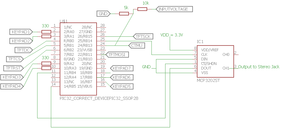
The keypad and TFT were implemented as in lab 2. We wired both according to the ECE 4760 TFT LCD and Keypad page.[1] We used 330 ohm resistors to pins A0 through A3 on the PIC and the pulldown/pullup macros for pins B7 through B9 for the keyboard. We confirmed that the keyboard was wired correctly by displaying the corresponding number or symbol on the TFT using the example code on the TFT and Keypad page. Since the keypad will only be for selecting modes, we chose not to play the DTMF frequency for each key and not to debounce the keys. The TFT displays the measurements as well as the mode selected and required no additional setup. We implemented the mode selection once the TFT and keypad were wired. Resistance mode is selected by pressing “7.” Capacitance mode is selected by pressing “8.” Voltage mode is selected by pressing “9.” The mode is confirmed by pressing the “#” key after selecting one of the previous numbers.

There were some pin contentions when we attempted to use the exact same wiring as in lab 2. Both the DAC and the SCK for the TFT were on pin 25 (SCK1) of the PIC32, so we moved the TFT SCK to pin 26 (AN9). The CTMU measurement occurred on pin 24 (AN11).

SPI DAC

The MCP4822 SPI DAC was also implemented as it was in lab 2. The MCP4822 is a 12-bit dual DAC, and we used output B of the DAC (pin 6) to send the voice to the external speaker. The SCK of the SPI DAC was connected to SCK1 (pin 25) of the PIC32. The active low CS of the DAC was connected to RB4 (pin 11), and the SDI of the DAC was connected to RB5 (pin 14). VDD was connected to the 3.3V power from the MicroStickII headers. LDAC was grounded since only one channel was being used, as was VSS. The internal reference voltage of this pin was 2.048V. No gain was specified.

Additional Measurement Hardware

Because of the CTMU, very little extra hardware is required for the measurement system. The only addition was a voltage divider used to protect the PIC32 pin when measuring high voltages. The voltage divider consists of a 10k and a 5k resistor, which maps 10V to 3.33V. The voltage divider determined the range of voltages that could be measured by the multimeter.

Potential Improvements

While our implementation functioned, the quality of the sound could have been improved by choosing a better DAC. We researched using an external R2R ladder and op-amp as a DAC since this setup would allow us more bits for the compressed signal. Using DPCM compression with the improved DAC would have greatly improved our sound quality; however, we were unable to implement this solution within the time allotted.

Additional consolidation of the hardware would allow this project to potentially develop into a product. We could take the PIC32 off of the MicroStickII, create a PCB for the system, and construct an enclosure. Enclosing the device would improve it’s usability, and the PCB would prevent any loose connection bugs to arise.

The schematic of the system can be found in Appendix C.

Results

As we we mentioned above, calibration was necessary for both resistance and voltage mode. We calibrated the voltage measurement by taking sample measurements about 1V apart between 0V and 10V and comparing the real voltage against the measured voltage.  We used the bench power supply to sweep the voltage and read the result of our voltage scaling calculation.  Once we had collected enough data points, we plotted them and found a line of best fit.  When we switched from the whiteboard to the solder board, the internal resistance appeared to be significantly different, so the calibration process was repeated.  The plot with line of best fit can be seen below.

Real vs ADC Voltage Graph

Fig. 1 - Real vs ADC Voltage Graph for Calibration Purposes

In the end, the talking multimeter works as expected, although we plan to improve the robustness of the system. Measurement values are sometimes be mispronounced, but that is certainly something we can work on in the near future. The speed of execution is quick, with little to no flickering or hesitation. Most importantly, measurements taken in all three modes were quite accurate upon calibration.


Resistor 1

Resistor 2

Resistor 3

Resistor 4

Resistor 5

Actual Resistance

330

1k

2k

10k

50k

Measured Value

336

998

1980

10034

49987

Percentage Error

1.82%

0.20%

1.00%

0.34%

0.03%

Table 1: Ohmmeter Measurments and Error Table


Capacitor 1

Capacitor 2

Capacitor 3

Capacitor 4

Capacitor 5

Actual Capacitance

1300pF

10uF

13uF

17uF

47uF

Measured Value

1280.47

9.87

12.58

15.78

46.95

Percentage Error

1.50%

1.30%

3.23%

7.18%

0.11%

Table 2: Capacitance Meter Measurments and Error Table


Voltage 1

Voltage 2

Voltage 3

Voltage 4

Voltage 5

Actual Voltage

2.00V

4.00V

6.05V

7.99V

9.23V

Measured Value

2.12

4.24

6.41

8.60

9.80

Percentage Error

6.00%

6.00%

5.95%

7.63%

6.18%

Table 3: Voltmeter Measurments and Error Table

Since our project consists of a reasonable amount of soldering, we made sure safety goggles were worn every soldering session. When it comes to the safety of the PIC32, we would always be sure to add in resistors to certain pins that may subject to high voltage spikes. Since our final product was quite low power and does not transmit wirelessly, we did not cause any kind of interference to nearby classmates. Finally, the usability of this project is extremely high. A talking multimeter can greatly benefit engineers, whether they have special needs or not. It provides the convenience of probing certain electronic components without having to look at the measurement screen, but only listening.


Conclusions

The overall experience of the project was extremely rewarding. Not only does it incorporate the skills acquired from labs 1-4 throughout the semester, our team being the only one that created this product also contributes to a more challenging debug situation for TAs. Although our final product measured resistance, capacitance, and voltage accurately, several other parts were not perfect, and many areas have high potential for improvement in the future. For example, our speech quality was quite low, we simply read out the values digit by digit instead of taking into account the overall value (e.g. twenty instead of two-zero). Even though our attempt on autoranging did not quite work, we would hope to implement a more robust one for resistance measurement by observing overflow-bits in the CTMU implementation. This could potentially give us another magnitude of resistance measurement range. Finally, the most important thing would be adaptive speech creation. This means if a resistor value has a been read and pronounced, and the user decides to unplug it and plug a different resistor in, it would automatically read that value proceed to speak the updated measurement without a hard reset on the device. The core of this project is quite software based, and if someone else were to replicate this, a tremendous amount of time would be spent reading through the datasheet of PIC32. Although we reused certain parts of the CTMU code from Professor Bruce Land’s ECE 4760 page, lots of tweakings were done in order to become the most suitable for our application and UI design. Other parts of the code are either reused from previous labs throughout the semester, or entirely new.

Our talking multimeter adheres strictly to IEEE’s Code of Ethics. Design decisions were certainly  made consistent with the law, safety, health, and welfare of the public. It does not endanger the public or the environment in any way. We did not encounter any sorts of conflicts of interest, and are prepared to disclose them to affected parties if that does happen. Our data presented were realistic. We did not receive any sort of bribery, and aimed to improve the appropriate application and understanding of this product as specified in the previous paragraph. Moreover, we are open to any sort of honest and constructive criticism because we strive for a more robust design. Each team member was treated fairly with absolutely no discrimination based on race, religion, gender, disability, age, national origin, sexual orientation, gender identity, or gender expression. With safety precautions done in all kinds of areas, we avoided any sort of injuries on others, their property, reputation, or employment by any sort of false or malicious action. Most importantly, we assisted and supported each other professionally through the design phase. As mentioned, this is a project of great potential. A fully functional and user-friendly talking multimeter can greatly benefit Electrical and Computer Engineers in lab as it provides the convenience of probing certain electronics without having to look at the measurement screen. However, it is absolutely crucial that the core requirements of the product is that measurements are both precise and accurate.

References

[1] Honeywell International Inc., "Speech synthesis and voice recognition in metrologic equipment", 20100070273 A1, 2016.

[2] B. Land, “Cornell University ECE4760 Adafruit TFT LCD Display Model 1480 and Keypad
PIC32MX250F128B,” ECE 4760, 2016. [Online]. Available: https://people.ece.cornell.edu/land/courses/ece4760/PIC32/index_TFT_display.html. [Accessed: 13-Sep-2016]

[3] B. Land, "Charge Time Measurement Unit (CTMU) PIC32MX250F128B", ECE 4760, 2015. [Online]. Available: http://people.ece.cornell.edu/land/courses/ece4760/PIC32/index_CTMU.html. [Accessed: 08- Dec- 2016].

[4] B. Land, "Charge Time Measurement Unit (CTMU) PIC32MX250F128B", ECE 4760, 2015. [Online]. Available: http://people.ece.cornell.edu/land/courses/ece4760/PIC32/index_CTMU.html. [Accessed: 08- Dec- 2016].

[5] B. Land, "Cornell University ECE4760 Digital Signal Processing PIC32MX250F128B.", Cornell University ECE 4760, 2015. [Online]. Available: https://people.ece.cornell.edu/land/courses/ece4760/PIC32/index_DSP.html. [Accessed: 04- Oct- 2016].

Appendices

Appendix A

The group approves this report for inclusion on the course website.

The group approves the video for inclusion on the course youtube channel.

Appendix B - Raw Code

/* 
 * lab5.c
 *
 * Final Project: Speech Multimeter
 *
 * Rachel Dipirro   (rdd49)
 * Jonathan Lo      (hl887)
*/
// Autorange = do it with overflow bit.
#include "config.h"
#include "tft_master.h"
#include "tft_gfx.h"
#include <stdlib.h>
#include <math.h>
#include <plib.h>
#include "pt_cornell_1_2_1.h"
#include "Mike_digits_8khz_packed.h"

//========================================================================
// DAC Macros
//========================================================================
#define DAC_config_chan_A 0b0011000000000000
#define DAC_config_chan_B 0b1011000000000000

//========================================================================
// ADC Setup Macros
//========================================================================
// ADC Setup for R Meter
#define PARAM1_R  ADC_FORMAT_INTG16 | ADC_CLK_AUTO | ADC_AUTO_SAMPLING_OFF //
#define PARAM2_R  ADC_VREF_AVDD_AVSS | ADC_OFFSET_CAL_DISABLE | ADC_SCAN_OFF | ADC_SAMPLES_PER_INT_1 | ADC_ALT_BUF_OFF | ADC_ALT_INPUT_OFF
#define PARAM3_R  ADC_CONV_CLK_PB | ADC_SAMPLE_TIME_31 | ADC_CONV_CLK_Tcy //ADC_SAMPLE_TIME_15| ADC_CONV_CLK_Tcy
#define PARAM4_R  ENABLE_AN11_ANA
#define PARAM5_R  SKIP_SCAN_ALL

// ADC Setup for C Meter
#define PARAM1_C  ADC_FORMAT_INTG16 | ADC_CLK_MANUAL | ADC_AUTO_SAMPLING_OFF //
#define PARAM2_C  ADC_VREF_AVDD_AVSS | ADC_OFFSET_CAL_DISABLE | ADC_SCAN_OFF | ADC_SAMPLES_PER_INT_1 | ADC_ALT_BUF_OFF | ADC_ALT_INPUT_OFF
#define PARAM3_C  ADC_CONV_CLK_PB | ADC_SAMPLE_TIME_15 | ADC_CONV_CLK_Tcy //ADC_SAMPLE_TIME_15| ADC_CONV_CLK_Tcy
#define PARAM4_C  ENABLE_AN9_ANA
#define PARAM5_C  SKIP_SCAN_ALL

//========================================================================
// Keypad Pull Up/Pull Down Macros
//========================================================================
//Port B
#define EnablePullDownB(bits)   CNPUBCLR=bits; CNPDBSET=bits;
#define DisablePullDownB(bits)  CNPDBCLR=bits;
#define EnablePullUpB(bits)     CNPDBCLR=bits; CNPUBSET=bits;
#define DisablePullUpB(bits)    CNPUBCLR=bits;
//PORT A
#define EnablePullDownA(bits)   CNPUACLR=bits; CNPDASET=bits;
#define DisablePullDownA(bits)  CNPDACLR=bits;
#define EnablePullUpA(bits)     CNPDACLR=bits; CNPUASET=bits;
#define DisablePullUpA(bits)    CNPUACLR=bits;

//========================================================================
// 16:16 Fixed Point Macros
//========================================================================
typedef signed int fix16 ;
#define multfix16(a,b) ((fix16)(((( signed long long)(a))*(( signed long long)(b)))>>16)) //multiply two fixed 16:16
#define float2fix16(a) ((fix16)((a)*65536.0)) // 2^16
#define fix2float16(a) ((float)(a)/65536.0)
#define fix2int16(a)   ((int)((a)>>16))
#define int2fix16(a)   ((fix16)((a)<<16))
#define divfix16(a,b)  ((fix16)((((signed long long)(a)<<16)/(b))))
#define sqrtfix16(a)   (float2fix16(sqrt(fix2float16(a))))
#define absfix16(a)    abs(a)
#define onefix16       0x00010000 // int2fix16(1)
#define sustain_constant float2fix16(256.0/20000.0) ; // seconds per decay update

//========================================================================
// some precise, fixed, short delays
// to use for cap charging time
#define NOP asm("nop");
// 1/2 microsec
#define wait20 NOP;NOP;NOP;NOP;NOP;NOP;NOP;NOP;NOP;NOP;NOP;NOP;NOP;NOP;NOP;NOP;NOP;NOP;NOP;NOP;
// one microsec
#define wait40 wait20;wait20;
//========================================================================

//========================================================================
// KEYS
//========================================================================
int resConfirm = 0;
int rMode = 0;
int R_new, R_old;
int dontgocrazy;
char ohmBuffer[20];
int rSpeechMode;

int capConfirm = 0;
int cMode = 0;
float C_new, C_old, C_nano;
int C_nanoint, C_decimal;
char capBuffer[20];
float fractpart, intpart;
int cSpeechMode;

int voltConfirm = 0;
int vMode = 0;
int showKey_pressed = 1;
float divVoltage;
float V_new, V_old;
int V_int;
char voltBuffer[20];
int vSpeechMode;

//========================================================================
// DAC and SPI
//========================================================================
volatile unsigned int DAC_data;
volatile SpiChannel spiChn = SPI_CHANNEL2 ; // the SPI channel to use
volatile int spiClkDiv = 2 ; // 20 MHz max speed for this DAC
int sys_time_seconds ;

//========================================================================
// Voice  
//========================================================================
int key_pressed;
volatile int end_index;
volatile int begin_index;
volatile unsigned int voice_i, voice_j, voice_packed, voice_value;
int playFlag;
char reset_voice = 0;
int desiredKey;     // This is for testing only!!! WARNING.
int len, digitLength;
int digitVar = 0;
int stop = 0;
int stableFlag;
int endFlag;
//========================================================================
// Protothreads
//========================================================================
char buffer[60];    // String buffer
char timerbuff[60]; // String buffer for timer
static struct pt pt_timer, pt_key, pt_ctmu, pt_voice;

//========================================================================
// ISR
//========================================================================
void __ISR(_TIMER_2_VECTOR, ipl2) Timer2Handler(void){
    mT2ClearIntFlag();
    // Voice
    if (playFlag){
        voice_j = voice_i >> 1;
        if(~(voice_i & 1)) voice_packed = AllDigits[voice_j];
        // If odd, get upper nibble
        if(voice_i & 1) voice_value = voice_packed >> 4;
        // If even, get lower nibble
        else voice_value = voice_packed & 0x0f;
        voice_i++;
        voice_j = voice_i >> 1;
        if(voice_j > end_index){
            playFlag = 0;           // Stop playing the word
            //reset_voice = 0;      // Prevent more voice creation
            if (!rSpeechMode && !vSpeechMode && !cSpeechMode) digitVar++;             // Go to the next digit if available
            dontgocrazy = 0;        // Prevents ohmBuffer from being constantly written, which makes things go crazy
            rSpeechMode = 0;
            cSpeechMode = 0;
            vSpeechMode = 0;
        }
    }
    else{
        voice_value = 0;            // Nothing sends to DAC
    }
    
    
    //SPI for Voice
    mPORTBClearBits(BIT_4);         // Start transaction
    DAC_data = DAC_config_chan_B | (voice_value<<5) ; // Shift for volume control
    WriteSPI2(DAC_data);
    while (SPI2STATbits.SPIBUSY);   // Wait for end of transaction
    mPORTBSetBits(BIT_4);           // End transaction
} //End ISR

//========================================================================
//======================= Timer Thread ===================================
//========================================================================
static PT_THREAD (protothread_timer(struct pt *pt))
{
    PT_BEGIN(pt);
    //tft_setCursor(0, 0);
    //tft_setTextColor(ILI9340_WHITE);  tft_setTextSize(1);
    //tft_writeString("Secs since boot\n");
     while(1) {
       // yield time 1 second
       PT_YIELD_TIME_msec(1000) ;
       
       // =================================================================== //
       // Putting the play because it will be slower, and stop speech correspondingly.
       if (rMode){
           if ((stableFlag) && (digitLength>=digitVar)){     // Stop at digit+unit, good for R mode
               playFlag = 1;
           }
           if (digitLength<digitVar+1 && !rSpeechMode)    endFlag = 1;
       }
       
       if (cMode){
            if ((stableFlag) && (digitLength+3>=digitVar)){     // Stop at digit+unit+2 decimal places, good for C mode
                playFlag = 1;
            }
            if (digitLength+3<digitVar+1 && !cSpeechMode)  endFlag = 1;
       }
       
       if (vMode){
           if ((stableFlag) && (digitLength+3>=digitVar)){     // Stop at digit+unit, good for R mode
               playFlag = 1;
           }
           if (digitLength+3<digitVar+1 && !vSpeechMode)    endFlag = 1;
       }
       
       if(rSpeechMode) playFlag = 1;
       if(cSpeechMode) playFlag = 1;
       if(vSpeechMode) playFlag = 1;
       
       // NEVER exit while
    } // END WHILE(1)
  PT_END(pt);
} // timer thread

//========================================================================
//======================= CTMU Thread ====================================
//========================================================================
// Mess with resistance measurement
static int pressedKey ;
static PT_THREAD (protothread_ctmu(struct pt *pt))
#define Vdd 3.3
#define ADC_max 1023.0
{
    PT_BEGIN(pt);
      static int raw_adc;
      static int tempvalR, k;
      static float I[4]={550e-6, 0.55e-6, 5.5e-6, 55e-6} ; // current settings in amps
      static int adc_zero[4]={113, 0, 0, 11}; // ADC reading with zero ohms at each current
      static float I_set, tempvalC, newFractpart, tempvalV;
//      static float fractpart, intpart;
      
      // CTMU Setup
      // Current Range IRNG 0x3 => 100x, approx 55 microamps;
      // IRNG 0x2 => 10x, approx 5.5 microamps
      // IRNG 0x1 => 1x, approx 0.55 microamps
      // IRNG 0x00 => 1000x, approx 550 microamps

      CTMUCONbits.ON = 1; // Turn on CTMU
      //CTMUCONbits.IRNG = 3; // set this in loop
      CTMUCONbits.IDISSEN = 0; // End drain of circuit
      CTMUCONbits.EDG1STAT = 1; // Begin charging the circuit

      while(1) {
          PT_YIELD_TIME_msec(30);
          //===================================================================
          //=================== RESISTANCE MEASUREMENT ========================
          //===================================================================                 
          while(rMode && (!rSpeechMode)){    // Check if resistance mode
            //CTMUCONbits.IRNG = 3; // set this in loop
            CTMUCONbits.IDISSEN = 0; // End drain of circuit
            CTMUCONbits.EDG1STAT = 1; // Begin charging the circuit
              
            PT_YIELD_TIME_msec(30);
            OpenADC10( PARAM1_R, PARAM2_R, PARAM3_R, PARAM4_R, PARAM5_R ); // configure ADC using the parameters defined above
            EnableADC10();
            tft_fillRoundRect(0,107, 10, 15, 0, ILI9340_BLACK);
            tft_setCursor(0, 107);
            tft_setTextColor(ILI9340_WHITE);  tft_setTextSize(2);
            tft_writeString("R: ");
            
            int currentSET = 2;
            
            I_set = I[currentSET];
            CTMUCONbits.IRNG = currentSET;

            CTMUCONbits.EDG1STAT = 1;
            AcquireADC10(); // start ADC sampling
            while (!AD1CON1bits.DONE){}; // Wait for ADC conversion
            // read the result of channel AN11 from the idle buffer
            raw_adc =  ReadADC10(0) ;
            // turn off current source
            CTMUCONbits.EDG1STAT = 0;
            // convert raw to resistance ADC reads 11 at zero resistance
            // Vref = Vdd = 3.3 ; current source=55 microamps
            
            R_old = R_new;  // For stabilization purposes
            R_new = (float)(raw_adc-adc_zero[currentSET])/ADC_max * Vdd / I_set ; // V/I = R           
            
            // Brute force calibration
            if (((int)R_new < 600) && (int)R_new>200) R_new = R_new - 250; // Works with 330 measurement
            if (((int)R_new < 1500) && (int)R_new>1000) R_new = R_new - 170; // Works with 1k measurement
            if (((int)R_new < 2500) && (int)R_new>2000) R_new = R_new - 340; // Works with 2k measurement
            
            // draw resistance results
            tft_fillRoundRect(40,107, 220, 20, 0, ILI9340_BLACK);// x,y,w,h,radius,color
            tft_setCursor(40, 107);
            tft_setTextColor(ILI9340_WHITE); tft_setTextSize(2);
            sprintf(buffer,"%d Ohm", (int)R_new );
            tft_writeString(buffer);
            //}
            
            if (R_new>0 && !stableFlag){   // If there is a reading on resistance, necessary, otherwise will crash if R_new = 0 (not reading anything).
                tempvalR = R_new;
                if(tempvalR>=10) len =  2; // Find the length of the value
                if(tempvalR>=100) len =  3;
                if(tempvalR>=1000) len =  4;
                if(tempvalR>=10000) len =  5;
                if(tempvalR>=100000) len =  6;
                if(tempvalR>=1000000) len =  7;
                if(tempvalR>=10000000) len =  8;
                if(tempvalR>=100000000) len =  9;
                if(tempvalR>=1000000000) len = 10;
                digitLength = len;  // digitLength is used to stop speech, variable len gets "--"ed, will get overwritten in following for loop, need to preserve it
                ohmBuffer[len] = 11; // Assign the last digit to be "ohm"
                for(k=tempvalR;len--; k=(int)(k/10)) ohmBuffer[len] = (k%10);
                // E.g. R = 9852, then ohmBuffer[0] = 9, ohmBuffer[1]=8, etc.
            }
        }
        //tft_fillRoundRect(0,130, 220, 50, 0, ILI9340_BLACK);// When another mode is selected, erase the ADC, R thing.  
        //===================================================================
        //================== CAPACITANCE MEASUREMENT ========================
        //===================================================================
        while(cMode && (!cSpeechMode)){   
            tft_fillRoundRect(0,107, 10, 15, 0, ILI9340_BLACK);
            tft_setCursor(0, 107);
            tft_setTextColor(ILI9340_WHITE);  tft_setTextSize(2);
            tft_writeString("C: ");

            //I_set = I[key_pressed];
            I_set = I[0];
            CTMUCONbits.IRNG = 0;
            
            PT_YIELD_TIME_msec(100);
            OpenADC10( PARAM1_C, PARAM2_C, PARAM3_C, PARAM4_C, PARAM5_C ); // configure ADC using the parameters defined above
            EnableADC10();
            // dischrge the cap
            AcquireADC10(); // start ADC sampling -- connects ADC sample cap to circuit
            // and discharge
            CTMUCONbits.IDISSEN = 1; // start drain of circuit
            PT_YIELD_TIME_msec(1); // wait for discharge
            CTMUCONbits.IDISSEN = 0; // End drain of circuit

            // start charging and wait 2 microsecs
            CTMUCONbits.EDG1STAT = 1;
            wait40;wait40;
            // end charging
            CTMUCONbits.EDG1STAT = 0;
            // Keep in between 0.1 - 1 V for each decade
            
            
            // stop samping and start conversion
            // note that in:
            //#define PARAM1  ADC_FORMAT_INTG16 | ADC_CLK_MANUAL | ADC_AUTO_SAMPLING_OFF
            // clock is manual and auto sampling is off
            ConvertADC10(); // end sampling & start conversion

            // wait for complete
            while (!AD1CON1bits.DONE){}; // Wait for ADC conversion

            // read the result of channel from the idle buffer
            raw_adc =  ReadADC10(0) ;

            // convert raw to resistance ADC reads 11 at zero resistance
            // Vref = Vdd = 3.3 ; 2 microsec charge pulse
            C_old = C_new;  // For stabilization purposes
            C_new = (I_set * 2e-6) / ((float)(raw_adc)/ADC_max * Vdd)  ; // c = q/v
            //if ((((int)C_new > 45) && ((int)C_new<55))||(((int)C_new > 25) && ((int)C_new<30)))   C_new = 99.12;
            C_nano = C_new/(1e-9);
            
            /*int C_temp = (int)C_nano;
            if (C_temp == 341)   C_new = (I_set * 2e-4) / ((float)(raw_adc)/ADC_max * Vdd)  ; // c = q/v*/

            // draw capacitance results
            // erase
            tft_fillRoundRect(40,107, 220, 20, 0, ILI9340_BLACK);// x,y,w,h,radius,color
            tft_setCursor(40, 107);
            tft_setTextColor(ILI9340_WHITE); tft_setTextSize(2);
            //sprintf(buffer,"%3.4e nF", C_nano);
            sprintf(buffer,"%.2f nF", C_nano);
            tft_writeString(buffer);


            if (C_nano>10 && !stableFlag){   // If there is a reading on resistance, necessary, otherwise will crash if R_new = 0 (not reading anything).
                C_nanoint = (int)C_nano;
                tempvalC = C_nanoint;
                if(tempvalC>=10) len =  2; // Find the length of the value
                if(tempvalC>=100) len =  3;
                if(tempvalC>=1000) len =  4;
                if(tempvalC>=10000) len =  5;
                if(tempvalC>=100000) len =  6;
                if(tempvalC>=1000000) len =  7;
                if(tempvalC>=10000000) len =  8;
                if(tempvalC>=100000000) len =  9;
                if(tempvalC>=1000000000) len = 10;
                digitLength = len;  // digitLength is used to stop speech, variable len gets "--"ed, will get overwritten in following for loop, need to preserve it
                capBuffer[len] = 10; // Assign the next digit to be "point"
                fractpart = modf(C_nano, &intpart);
                newFractpart = (fractpart*100);   // To get the 2 decimal values
                capBuffer[len+1] = (((int)newFractpart/10)%10);   // First decimal
                capBuffer[len+2] = ((int)newFractpart%10);   // Second decimal
                capBuffer[len+3] = 13; // Assign the last digit to be "nano-farad"
                // For loop goes after the above before len gets overwriten.
                for(k=tempvalC;len--; k=(int)(k/10)) capBuffer[len] = (k%10);
                // Force to always pronounce 2 decimals
            }
            else if (C_nano<10 && !stableFlag){
                C_nanoint = (int)C_nano;
                tempvalC = C_nanoint;
                len = 1;
                digitLength = len;
                capBuffer[len-1] = tempvalC;
                capBuffer[len] = 10;
                fractpart = modf(C_nano, &intpart);
                newFractpart = (fractpart*100);   // To get the 2 decimal values
                capBuffer[len+1] = (((int)newFractpart/10)%10);   // First decimal
                capBuffer[len+2] = ((int)newFractpart%10);   // Second decimal
                capBuffer[len+3] = 13; // Assign the last digit to be "nano-farad"   
            }
            
        }
        //tft_fillRoundRect(0,80, 220, 50, 0, ILI9340_BLACK);// When another mode is selected, erase the Capacitance: thing.
        //===================================================================
        //================== VOLTMETER MEASUREMENT ==========================
        //===================================================================
        while(vMode && (!rSpeechMode)){
            PT_YIELD_TIME_msec(100); // To be modified depending on load
            //CTMUCONbits.IRNG = 3; // set this in loop
            CTMUCONbits.IDISSEN = 0; // End drain of circuit
            CTMUCONbits.EDG1STAT = 1; // Begin charging the circuit

            OpenADC10( PARAM1_R, PARAM2_R, PARAM3_R, PARAM4_R, PARAM5_R ); // configure ADC using the parameters defined above
            EnableADC10();
            
            I_set = I[3];
            CTMUCONbits.IRNG = 3;

            CTMUCONbits.EDG1STAT = 1;
            AcquireADC10(); // start ADC sampling
            while (!AD1CON1bits.DONE){}; // Wait for ADC conversion
            // read the result of channel AN11 from the idle buffer
            raw_adc =  ReadADC10(0) ;
            // turn off current source
            CTMUCONbits.EDG1STAT = 0;
            // convert raw to resistance ADC reads 11 at zero resistance
            // Vref = Vdd = 3.3 ; current source=55 microamps
            //tft_fillRoundRect(0,80, 220, 50, 1, ILI9340_BLACK);// When another mode is selected, erase previous words:
            
            // 0V    = raw_adc @ 70
            // 1.33V = raw_adc @ 214
            // 2.33V = raw_adc @ 322
            // 3.34V = raw_adc @ 431
            // 4.34V = raw_adc @ 536
            // 5.34V = raw_adc @ 644
            // 6.34V = raw_adc @
            // Max @ raw_adc = 1024 (9.84V)
                       
            OpenADC10( PARAM1_R, PARAM2_R, PARAM3_R, PARAM4_R, PARAM5_R ); // configure ADC using the parameters defined above
            EnableADC10();
            AcquireADC10(); // start ADC sampling
            while (!AD1CON1bits.DONE){}; // Wait for ADC conversion
            // read the result of channel AN11 from the idle buffer
            raw_adc =  ReadADC10(0) ;
            // Equation created using Excel y = 111x - 20.143
            V_old = V_new;
            divVoltage = (raw_adc+3.5714)/107.89 + 0.05;
            V_new = divVoltage;
            
            tft_fillRoundRect(0,107, 10, 15, 0, ILI9340_BLACK);
            tft_setCursor(0, 107);
            tft_setTextColor(ILI9340_WHITE);  tft_setTextSize(2);
            tft_writeString("V: ");
            
            tft_fillRoundRect(40,107, 220, 20, 0, ILI9340_BLACK);
            tft_setCursor(40, 107);
            tft_setTextColor(ILI9340_WHITE); tft_setTextSize(2);
            //sprintf(buffer,"%d V", endFlag);
            sprintf(buffer,"%.2f V", V_new);
            tft_writeString(buffer);
            
            if (V_new!=0 && !stableFlag){   // If there is a reading on resistance, necessary, otherwise will crash if R_new = 0 (not reading anything).
                V_int = (int)V_new;
                tempvalV = V_int;
                len = 1;
                digitLength = len;  // digitLength is used to stop speech, variable len gets "--"ed, will get overwritten in following for loop, need to preserve it
                voltBuffer[len-1] = V_int;
                voltBuffer[len] = 10; // Assign the next digit to be "point"
                fractpart = modf(V_new, &intpart);
                newFractpart = (fractpart*100);   // To get the 2 decimal values
                voltBuffer[len+1] = (((int)newFractpart/10)%10);    // First decimal
                voltBuffer[len+2] = ((int)newFractpart%10);         // Second decimal
                voltBuffer[len+3] = 14; // Assign the last digit to be "volts"
            }
        }
        //tft_fillRoundRect(0,80, 220, 50, 0, ILI9340_BLACK);// When another mode is selected, erase the Voltage: thing.
        //====================================================================
        PT_YIELD_TIME_msec(30);
        // NEVER exit while
      } // END WHILE(1)
  PT_END(pt);
} // ctmu thread

//========================================================================
//============================ Key Thread ================================
//========================================================================
static PT_THREAD (protothread_key(struct pt *pt))
{
    PT_BEGIN(pt);
    static int keypad, pattern, stableCount;
    static int keytable[12]={0x108, 0x81, 0x101, 0x201, 0x82, 0x102, 0x202, 0x84, 0x104, 0x204, 0x88, 0x208};
    mPORTASetPinsDigitalOut(BIT_0 | BIT_1 | BIT_2 | BIT_3); //Set port as output
    mPORTBSetPinsDigitalIn(BIT_7 | BIT_8 | BIT_9);          //Set port as input

    /*// For debug purposes only
    tft_setCursor(0, 180);
    tft_setTextColor(ILI9340_WHITE);
    tft_setTextSize(1);
    tft_writeString("Current Value of key_pressed: ");*/

    while(1) {
        mPORTAClearBits(BIT_0 | BIT_1 | BIT_2 | BIT_3);
        pattern = 1; mPORTASetBits(pattern);

        PT_YIELD_TIME_msec(30);
        for (key_pressed=0; key_pressed<4; key_pressed++) {
            keypad  = mPORTBReadBits(BIT_7 | BIT_8 | BIT_9);
            if(keypad!=0) {keypad |= pattern ; break;}
            mPORTAClearBits(pattern);
            pattern <<= 1;
            mPORTASetBits(pattern);
        }

        // search for keycode
        if (keypad > 0){ // then button is pushed
            for (key_pressed=0; key_pressed<12; key_pressed++){
                if (keytable[key_pressed]==keypad) break;
            }
        }
        else key_pressed = -1; // no button pushed

       /*// For debug purposes only  // draw key number
        tft_fillRoundRect(190,180, 30, 15, 0, ILI9340_BLACK);// x,y,w,h,radius,color
        tft_setCursor(190, 180);
        tft_setTextColor(ILI9340_YELLOW); tft_setTextSize(2);
        sprintf(buffer,"%d", showKey_pressed);*/
        pressedKey = key_pressed;
        
        if (stableFlag && !dontgocrazy && !endFlag){
            if(rMode) desiredKey = ohmBuffer[digitVar];
            if(cMode) desiredKey = capBuffer[digitVar];
            if(vMode) desiredKey = voltBuffer[digitVar];
            dontgocrazy = 1;
        }
        else if (rSpeechMode && !dontgocrazy){
            desiredKey = 15;
            dontgocrazy = 1;
        }
        else if (cSpeechMode && !dontgocrazy){
            desiredKey = 16;
            dontgocrazy = 1;
        }
        else if (vSpeechMode && !dontgocrazy){
            desiredKey = 17;
            dontgocrazy = 1;
        }
        else
            /* Some big number that cannot be matched in the switch function
             * within the voice thread. This number will never be reached to stop.*/            
            desiredKey = 1000;        
        
        // For debug purposes only
        // tft_writeString(buffer);
        // ====================================================================
        // ==================== Mode selection begins here=====================
        // ====================================================================
        if (key_pressed == 7){
            resConfirm = 1;   
            capConfirm = 0;  
            voltConfirm = 0;  
            tft_fillRoundRect(0,50, 240, 30, 0, ILI9340_BLACK);
            tft_setCursor(18, 50);
            tft_setTextColor(ILI9340_WHITE); tft_setTextSize(2);
            tft_writeString("Ohmmeter Selected");
            tft_setCursor(12, 70);
            tft_writeString("Press # to Confirm");
        }
        else if (key_pressed == 8){
            resConfirm = 0;  
            capConfirm = 1;  
            voltConfirm = 0;
            tft_fillRoundRect(0,50, 240, 30, 0, ILI9340_BLACK);
            tft_setCursor(12, 50);
            tft_setTextColor(ILI9340_WHITE); tft_setTextSize(2);
            tft_writeString("Cap Meter Selected");
            tft_setCursor(12, 70);
            tft_writeString("Press # to Confirm");
        }
        else if (key_pressed == 9){
            resConfirm = 0;   
            capConfirm = 0;  
            voltConfirm = 1;  
            tft_fillRoundRect(0,50, 240, 30, 0, ILI9340_BLACK);
            tft_setCursor(12, 50);
            tft_setTextColor(ILI9340_WHITE); tft_setTextSize(2);
            tft_writeString("Voltmeter Selected");
            tft_setCursor(12, 70);
            tft_writeString("Press # to Confirm");
        }
        
        if (key_pressed==11 && resConfirm==1){
            tft_fillRoundRect(0,50, 240, 40, 0, ILI9340_BLACK);
            tft_fillRoundRect(0,130, 240, 14, 0, ILI9340_BLACK);
            tft_setCursor(33, 55);
            tft_setTextColor(ILI9340_GREEN); tft_setTextSize(3);
            tft_writeString("Resistance");
            rSpeechMode = 1;
            // Then Toggle flag for R meter mode
            rMode = 1;  // Resistance meter is officially selected
            cMode = 0;  // Turn off
            vMode = 0;  // Turn off
            stableCount = 0; // Reset stable counter upon switching to different mode
            stableFlag = 0;
            digitVar = 0;
            endFlag = 0;
        }
        else if (key_pressed==11 && capConfirm==1){
            tft_fillRoundRect(0,50, 240, 40, 0, ILI9340_BLACK);
            tft_fillRoundRect(0,130, 240, 14, 0, ILI9340_BLACK);
            tft_setCursor(20, 55);
            tft_setTextColor(ILI9340_GREEN); tft_setTextSize(3);
            tft_writeString("Capacitance");
            cSpeechMode = 1;
            // Then Toggle flag for C meter mode
            rMode = 0;  // Turn off
            cMode = 1;  // Capacitance meter is officially selected
            vMode = 0;  // Turn off           
            stableCount = 0; // Reset stable counter upon switching to different mode
            stableFlag = 0;
            digitVar = 0;
        }
        else if (key_pressed==11 && voltConfirm==1){
            tft_fillRoundRect(0,50, 240, 40, 0, ILI9340_BLACK);
            tft_fillRoundRect(0,130, 240, 14, 0, ILI9340_BLACK);
            tft_setCursor(0, 55);
            tft_setTextColor(ILI9340_GREEN); tft_setTextSize(3);
            tft_writeString("   Voltage");
            vSpeechMode = 1;
            // Then Toggle flag for V meter mode
            rMode = 0;  // Turn off
            cMode = 0;  // Turn off
            vMode = 1;  // Voltmeter is officially selected
            stableCount = 0; // Reset stable counter upon switching to different mode
            stableFlag = 0;
            digitVar = 0;
        }
        
        // ==================================================================
        if (rMode){
            if (R_new > 0 && !stableFlag){     // If R has begun measuring, then activate stabilization code
                if (R_old == R_new){
                    stableCount++;   // Increment until stable value reached (Handled in another thread)         
                }
                else
                    stableCount = 0; // Reset

                if (stableCount >= 7) {    // 12 obtained from trial and error, how long it takes to stabilize value?
                    
                    tft_fillRect(0, 130, 240, 20, ILI9340_GREEN);
                    tft_setCursor(1, 132);
                    tft_setTextColor(ILI9340_BLACK); tft_setTextSize(2);
                    tft_writeString("Stabilized at ");
                    stableFlag = 1;// Set a stable flag
                    sprintf(buffer,"%d", R_old);
                    tft_writeString(buffer);
                }
                else{
                    tft_fillRect(0, 130, 240, 20, ILI9340_RED);
                    tft_setCursor(1, 132);
                    tft_setTextColor(ILI9340_BLACK); tft_setTextSize(2);
                    tft_writeString("Waiting to stabilize...");
                }
            }
        }
        
        if (cMode){
            if (C_new > 0 && !stableFlag){
                if (C_old == C_new){
                    stableCount++;   // Increment until stable value reached (Handled in another thread)         
                }
                else
                    stableCount = 0; // Reset
                
                if (stableCount >= 4) {    // 12 obtained from trial and error, how long it takes to stabilize value?
                    tft_fillRect(0, 130, 240, 20, ILI9340_GREEN);
                    tft_setCursor(1, 132);
                    tft_setTextColor(ILI9340_BLACK); tft_setTextSize(2);
                    tft_writeString("Stabilized at ");
                    stableFlag = 1;// Set a stable flag
                    sprintf(buffer,"%.2f", C_nano);
                    tft_writeString(buffer);   
                }
                else{
                    tft_fillRect(0, 130, 240, 20, ILI9340_RED);
                    tft_setCursor(1, 132);
                    tft_setTextColor(ILI9340_BLACK); tft_setTextSize(2);
                    tft_writeString("Waiting to stabilize...");
                }
            }
        }
        if (vMode){
            if (V_new > 0 && !stableFlag){
                if (V_old == V_new){
                    stableCount++;   // Increment until stable value reached (Handled in another thread)         
                }
                else
                    stableCount = 0; // Reset
                
                if (stableCount >= 10) {    // 12 obtained from trial and error, how long it takes to stabilize value?
                    tft_fillRect(0, 130, 240, 20, ILI9340_GREEN);
                    tft_setCursor(1, 132);
                    tft_setTextColor(ILI9340_BLACK); tft_setTextSize(2);
                    tft_writeString("Stabilized at ");
                    stableFlag = 1;// Set a stable flag
                    sprintf(buffer,"%.2f", V_old);
                    tft_writeString(buffer);   
                }
                else{
                    tft_fillRect(0, 130, 240, 20, ILI9340_RED);
                    tft_setCursor(1, 132);
                    tft_setTextColor(ILI9340_BLACK); tft_setTextSize(2);
                    tft_writeString("Waiting to stabilize...");
                }
            }
        }
        // NEVER exit while
    } // END WHILE(1)
  PT_END(pt);
} // keypad thread

// ==============================================================
// ==================== Voice Thread ============================
// ==============================================================
static PT_THREAD (protothread_voice(struct pt *pt))
{
    PT_BEGIN(pt);
    static int pattern;

    // Init the keypad pins A0-A3 and B7-B9, and PortA ports as digital outputs
    mPORTASetPinsDigitalIn(BIT_0 | BIT_1 | BIT_2 | BIT_3);    //Set port as input
    mPORTBSetPinsDigitalIn(BIT_7 | BIT_8 | BIT_9);    //Set port as input

    while(1) {
        // read each row sequentially
        mPORTASetPinsDigitalOut(BIT_0); //Set A0 as output
        mPORTAClearBits(BIT_0 | BIT_1 | BIT_2 | BIT_3);
        pattern = 1; mPORTASetBits(pattern);
        
        //=== Keypad Code=================================================
        // yield time
        PT_YIELD_TIME_msec(10);
 
        //====Set voice and test mode=====================================
        switch(desiredKey){
            // The following are indexes for the digits.
            case 0:
                reset_voice = 1;    // Only toggle reset voice when a digit is to be pronounced.
                begin_index = 0;
                end_index = 2400;
                showKey_pressed = 0;
                break;
            case 1:
                reset_voice = 1;
                begin_index = 2461;
                end_index = 3787;
                showKey_pressed = 1;
                break;
            case 2:
                reset_voice = 1;
                begin_index = 4912;
                end_index = 6656;
                showKey_pressed = 2;
                break;
            case 3:
                reset_voice = 1;
                begin_index = 7088;
                end_index = 8864;
                showKey_pressed = 3;
                break;
            case 4:
                reset_voice = 1;
                begin_index = 9344;
                end_index = 11232;
                showKey_pressed = 4;
                break;
            case 5:
                reset_voice = 1;
                begin_index = 11712;
                end_index = 14080;
                showKey_pressed = 5;
                break;
            case 6:
                reset_voice = 1;
                begin_index = 14192;
                end_index = 16496;
                showKey_pressed = 6;
                break;
            case 7:
                reset_voice = 1;
                begin_index = 16816;
                end_index = 19344;
                showKey_pressed = 7;
                break;
            case 8:
                reset_voice = 1;
                begin_index = 19648;
                end_index = 20848;
                showKey_pressed = 8;
                break;
            case 9:
                reset_voice = 1;        
                begin_index = 21184;
                end_index = 23719;
                showKey_pressed = 9;
                break;
            // The following are correct indexes for the words
            case 10:   // Point
                reset_voice = 1;
                begin_index = 23719;
                end_index = 24519;
                break;
            case 11:     // Ohm
                reset_voice = 1;
                begin_index = 24520;
                end_index = 25500;
                break;
            case 12:     // Kilo-ohm
                reset_voice = 1;
                begin_index = 25501;
                end_index = 28200;
                break;
            case 13:     // Nano-Farad
                reset_voice = 1;
                begin_index = 28201;
                end_index = 31000;
                break;
            case 14:     // Volt
                reset_voice = 1;
                begin_index = 31000;
                end_index = 31700;
                break;
            case 15:     // Resistance
                reset_voice = 1;
                begin_index = 31701;
                end_index = 34200;
                break;
            case 16:     // Capacitance
                reset_voice = 1;
                begin_index = 34201;
                end_index = 37201;
                break;
            case 17:     // Voltage
                reset_voice = 1;
                begin_index = 37202;
                end_index = 41284;
                break;
            case 1000:
                reset_voice = 0;
        }
        
        // Set new voice, reset_voice is toggled back to 0 after a digit
        // has finished producing. Only when a case is matched
        if(reset_voice){
            voice_i = begin_index << 1;
            reset_voice = 0;
        }
                       
        // NEVER exit while
    } // END WHILE(1)
    PT_END(pt);
} // keypad thread


void main(void) {
    SYSTEMConfigPerformance(PBCLK);
    ANSELA = 0; ANSELB = 0; CM1CON = 0; CM2CON = 0;

    PT_setup();
    INTEnableSystemMultiVectoredInt(); // Setup system wide interrupts
    
    EnablePullDownB( BIT_7 | BIT_8 | BIT_9); // Keypad Config
    SetChanADC10( ADC_CH0_NEG_SAMPLEA_NVREF | ADC_CH0_POS_SAMPLEA_AN11 ); // configure to sample AN11
    
    // Initialize Threads
    PT_INIT(&pt_timer);
    PT_INIT(&pt_key);
    PT_INIT(&pt_ctmu);
    PT_INIT(&pt_voice);

    // Initialize TFT
    tft_init_hw();
    tft_begin();
    tft_fillScreen(ILI9340_BLACK);
    tft_setRotation(0); // Use tft_setRotation(1) for 320x240
    
    // Timer Interrupt
    // Set up timer2 on,  interrupts, internal clock, prescalar 1, toggle rate
    // at 40 MHz PB clock 60 counts is two microsec
    // 5000 is 8 ksamples/sec
    OpenTimer2(T2_ON | T2_SOURCE_INT | T2_PS_1_1, 5000);
    ConfigIntTimer2(T2_INT_ON | T2_INT_PRIOR_2);
    mT2ClearIntFlag();
    PPSOutput(2, RPB5, SDO2); // SDO2 (MOSI) is in PPS output group 2, could be connected to RB5 which is pin 14

    // DAC Chip Select
    mPORTBSetPinsDigitalOut(BIT_4);
    mPORTBSetBits(BIT_4);
            
    SpiChnOpen(spiChn, SPI_OPEN_ON | SPI_OPEN_MODE16 | SPI_OPEN_MSTEN | SPI_OPEN_CKE_REV , spiClkDiv);    
    
    tft_fillRoundRect(0,240, 100, 14, 0, ILI9340_BLACK);
    tft_setCursor(40, 245);
    tft_setTextColor(ILI9340_YELLOW); tft_setTextSize(2);
    tft_writeString("Instructions");
    tft_drawLine(0, 267, 240, 267, ILI9340_YELLOW);
    tft_drawLine(0, 95, 240, 95, ILI9340_YELLOW);
    tft_setCursor(10, 275);
    tft_setTextSize(1);
    tft_writeString("Press 7 to Select Resistance Meter");
    tft_setCursor(10, 290);
    tft_writeString("Press 8 to Select Capacitance Meter");
    tft_setCursor(10, 305);
    tft_writeString("Press 9 to Select Voltage Meter");
    
    //Press 7 for R Meter \nPress 8 for C Meter \nPress 9 for V Meter\n
    
    tft_setCursor(70, 0);
    tft_setTextColor(ILI9340_YELLOW); tft_setTextSize(2);
    tft_writeString("ECE 4760\n Talking Multimeter\n");
    tft_drawLine(0, 40, 240, 40, ILI9340_YELLOW);
    
    while (1){
        PT_SCHEDULE(protothread_timer(&pt_timer));
        PT_SCHEDULE(protothread_voice(&pt_voice));
        PT_SCHEDULE(protothread_ctmu(&pt_ctmu));
        PT_SCHEDULE(protothread_key(&pt_key));
    }
} // main
// === end  ==============================================================

Appendix C

Schematics

Appendix D

Budget Considerations

We worked to develop a low-cost design that could be easily replicated. We used exclusively parts from lab so we wouldn't have to wait on shipping. Most of our budget goes to the hardware lab rentals, and even with the exorbitant amount of headers, we remained well under the $100 budget. The cost of wires, resistors, solder, lab space and equipment, and labor are not included in this budget.

Name Quantity Price
PIC32MX250F128B 1 5
MicroStickII 1 10
TFT LCD 1 10
Keypad 1 6
Solder board 1 2.50
Headers 61 3.05
Jumper Cables 4 0.40
Speaker (w/ AUX adapter) 1 2
MCP4822 SPI DAC 1 1.48
40.43

Appendix E

Task Division

Rachel specified the design for the project proposal, reasearched potential methods of speech generation and CTMU usage, organized the pin allocation, designed and debugged software, and soldered the final circuit. Jonathan designed and implemented most of the software, maintained the neatness of the whiteboard circuit, and debugged both hardware and software problems. Both participated in developing the website and writing the final report.