Motorized Camera Dolly
A Project By:
Sacheth Hegde - ssh88
Ope Oladipo - ooo25
Jason Zhang - jcz28
Contents:
Introduction
High Level Design
Design
Results
Conclusion
Appendix:
A - Release Permission
B - Program Listing
C - Schematics
D - Cost Details
E - Task Breakdown
F - References
Introduction
Oftentimes, photographers need to create moving timelapses across a landscape. A motorized camera dolly can be used to create these. The dolly is essentially a moving robot with the ability to move the camera position as well. Photographers can program the dolly with certain motions and place it on a landscape. After setting the time-lapse mode on, the camera dolly will move accordingly and take the timelapse until the photographer determines the shot to be sufficient.
Our camera dolly can be controlled using an iPhone application that we created. There are two modes: free mode, where the photographer can manually control the dolly or camera angle, and programmed mode, where the photographer can program many different actions (such as moving forward, moving the camera, etc.) over a time period so the time lapse can be complete.
High Level Design
Project Rationale
Ope Oladipo, one of the members of our group, is an avid photographer (you can check out some of his photography here). One of the common photography/videography practices includes timelapses, which are held for a long period of time and show a changing landscape spedup. Camera dollies (an example of a professional setup can be seen here) are used to hold cameras and slowly move over time to capture a timelapse. The have the ability to control the speed of the camera and slowly update the angle. These end up creating very professional looking timelapses. What is important here is to make sure movement is consistent and stable so the motion through the timelapse is seemless. Therefore, our goal was to end up making one of these camera dollies that could be used to make professional looking timelapses. Additionally, if the user wanted to, we wanted the ability to have free control if necessary to move the dolly to a given location manually.
Logical Structure
As mentioned in the Introduction, the high level view of our project includes an iPhone application, which is used to control the motorized dolly. The layout for this can be seen in the block diagram below.

Tradeoffs
Most of the tradeoffs we encountered occurred on the hardware portion, both with the "electronic hardware" and "mechanical hardware". The motors we used were not necessarily powerful. They are meant for light loads due to less torque. For the stepper motor, we found that under extremeley heavy loads, the motor would actually not spin all the way as we programmed it to, so we had to use lighter camera support to make sure there were no issues on the stepper motor side. Another tradeoff that we faced for the stepper motor specifically involved the tradeoff between speed and torque in the available motors that we had. At the same time, for the DC motors, heavier loads did impact the speed; however this is not necesarily a bad thing for our use case. Camera dollies for timelapses generally don't go at high speeds, so there were no issues at lower speeds and having lower maximum velocities. This issues mainly came with stalling that happened (at heavier loads and low speed configurations), but this was not a big problem that we faced. On the software side, our tradeoffs mainly involved work from the iPhone application and the PIC32. Most of the control obviously occured on the PIC32, which received bluetooth control signals and changed the behavior of the on-board motors. However, in the end, we determined that the iPhone would only be in charge of the very basic UI components and some simple timing to send control signals (for programmed mode), and everything else, including stepper motor timing and command parsing occured on the software side of the PIC32.
Program and Hardware Design
Program Details
As mentioned, we wrote code to work on an iPhone app and the PIC32. We will first talk about the PIC32 software implementation.
There was no TFT requirement for this lab, so we did not need to use any of the communication pins for TFT display. As with most of the labs, we used the ProtoThread library to perform most of the threading to collect data, perform actions, etc.
To rotate the stepper clockwise, the phases must be sequenced from 1 to 4 (the reasoning for which will be described in the hardware section), wrapping around after phase 4 has completed. To rotate the stepper counterclockwise, the phases must be sequenced in the opposite direction. A protothread was used to handle the rotation of the stepper motor. The 4 phases were encoded within this protothread, and the phase of the stepper was updated each time the protothread yielded. Using this scheme, we could vary the rate of rotation by varying the length of time that the protothread yields for. A shorter yield time leads to a faster rotation speed because the phase of the stepper is updated more frequently. Conversely, a longer yield time will lead to a slower stepper rotation speed.
For receiving data from the iPhone application, a serial input protothread handles the receiving functions on the UART. Within this protothread, a thread is spawned that waits for a valid input from the bluetooth module. The spawned thread is non-blocking, so other threads can execute while the bluetooth module does not have a valid message to give the PIC32. Once a message is received from the bluetooth module, the spawned thread is killed and the input protothread parses the message to determine the course of action that should be taken. The following list enumerates the messages that are recognized by the PIC32, as well as the actions that are taken upon receiving the message:
| "RST" | • Stops all movement of the robot wheels • Sets the robot speed and stepper rotation rate to default values |
| “ASPD {time in seconds}” | • Sets the length of time it will take to rotate the stepper to the angle specified in the “ANG” command |
| “ANG {angle between 0 and 360}” | • Rotates the stepper to the angle specified |
| “SPD {number from 0 to 100}” | • Sets the speed at which the robot should move |
| “UP” | • Moves the robot forward indefinitely |
| “DOWN” | • Moves the robot backwards indefinitely |
| “LEFT” | • Rotates the robot counterclockwise indefinitely |
| “RIGHT” | • Rotates the robot clockwise indefinitely |
| “STP” | • Stops all movement of the robot wheels |
Operation of the robot requires no transmission from the PIC32 to the iPhone app. However, during development, we experimented with transmitting messages through the bluetooth module. For speedy transmissions, we set up DMA channel 1 on the PIC32 to transfer the contents of a buffer in memory to the UART2 TX register. The DMA channel transfers each byte of the buffer until a null character is reached. To transmit a message, the buffer must first be written with a string. The program must then spawn a thread which activates the DMA channel to begin the memory transfer, wait until the memory transfer is complete, wait until the UART2 transmit buffer is empty, then kill itself. During this time, other threads are not blocked from execution.
The iPhone app was made with XCode using Swift 3. The basic procedure for this involves starting a new project, dragging the UI in place then implementing the functions, buttons and roles. A key feature of our app was it had bluetooth functionality. Apple has a CoreBluetooth library which we used along with a wrapper (by Alex AKA Hoiberg42) to simplify the bluetooth part. Steps to connect to bluetooth include:
- Turning on bluetooth (or making sure it’s turned on)
- We then scan all bluetooth devices with the UUID “FFE0”. This is the UUID particularly coupled with all HM-10 devices. This makes it easy to switch around bluetooth interfaces
- We connect to the first/closest hm-10 device we see.
- This fires a delegate (called callbacks in other languages) that informs us of this. We then change the UI to reflect this state of being connected.
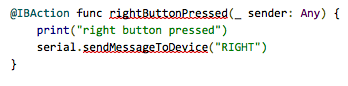
Free mode’s buttons are mapped to instructions that send messages as string over bluetooth. An example of this is below.
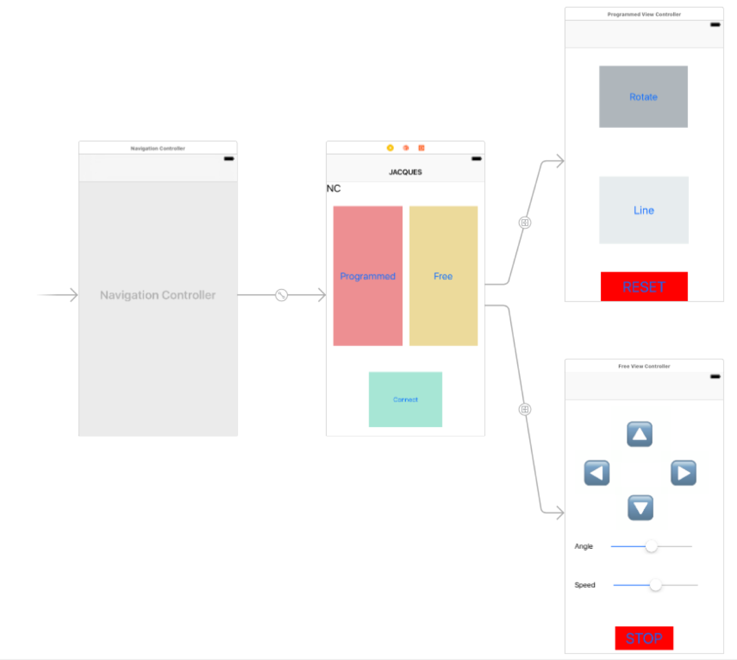
Moving over to programmed mode, there are 3 buttons. A reset button resets the state and calibrates the phone rotator. Meaning it takes the current value of the stepper motor and sets that as 180 degrees. The line button is a programmable button that allows the robot to move in a line for a specified amount of seconds. We specify direction, time it should take and speed it should move at. We send in all these values (but the time) to the pic which begins the transaction. The app then tells it to stop based on a timer (from the NSTimer library) we initialize on the phone while sending the values. These inputs are made possible by a UIAlertView and text inputs. The Rotate button takes in an angle and a time to rotate the phone by a certain amount of degrees for a specified amount of time. This is a basic overview of how the app works; there is a lot of error checking involved (swift is a relatively safe language) and a bunch of UI knowledge needed to replicate this. A basic flow of the view controllers can be seen below.
Hardware Details
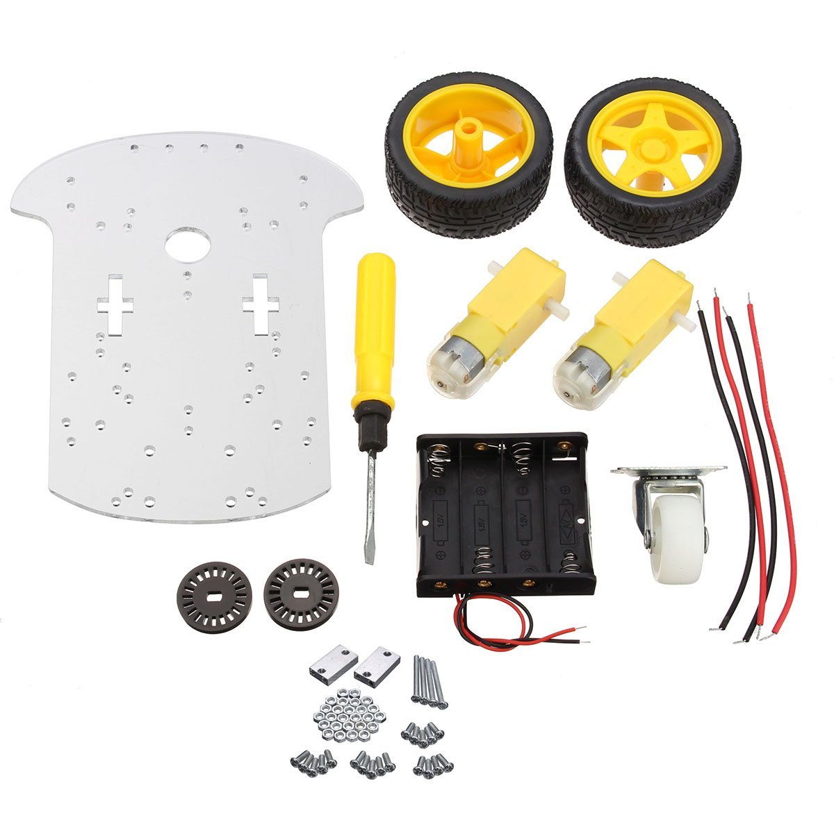
All of the hardware was contained within the robot vehicle, and was self-contained without the need for a separate power supply. We used a chassis for the car that we bought online, which came with a transparent laser-cutter chassis, two wheels, two DC motors, and a pivoting wheel to provide support for the front of the vehicle. The example parts can be seen in the picture below.
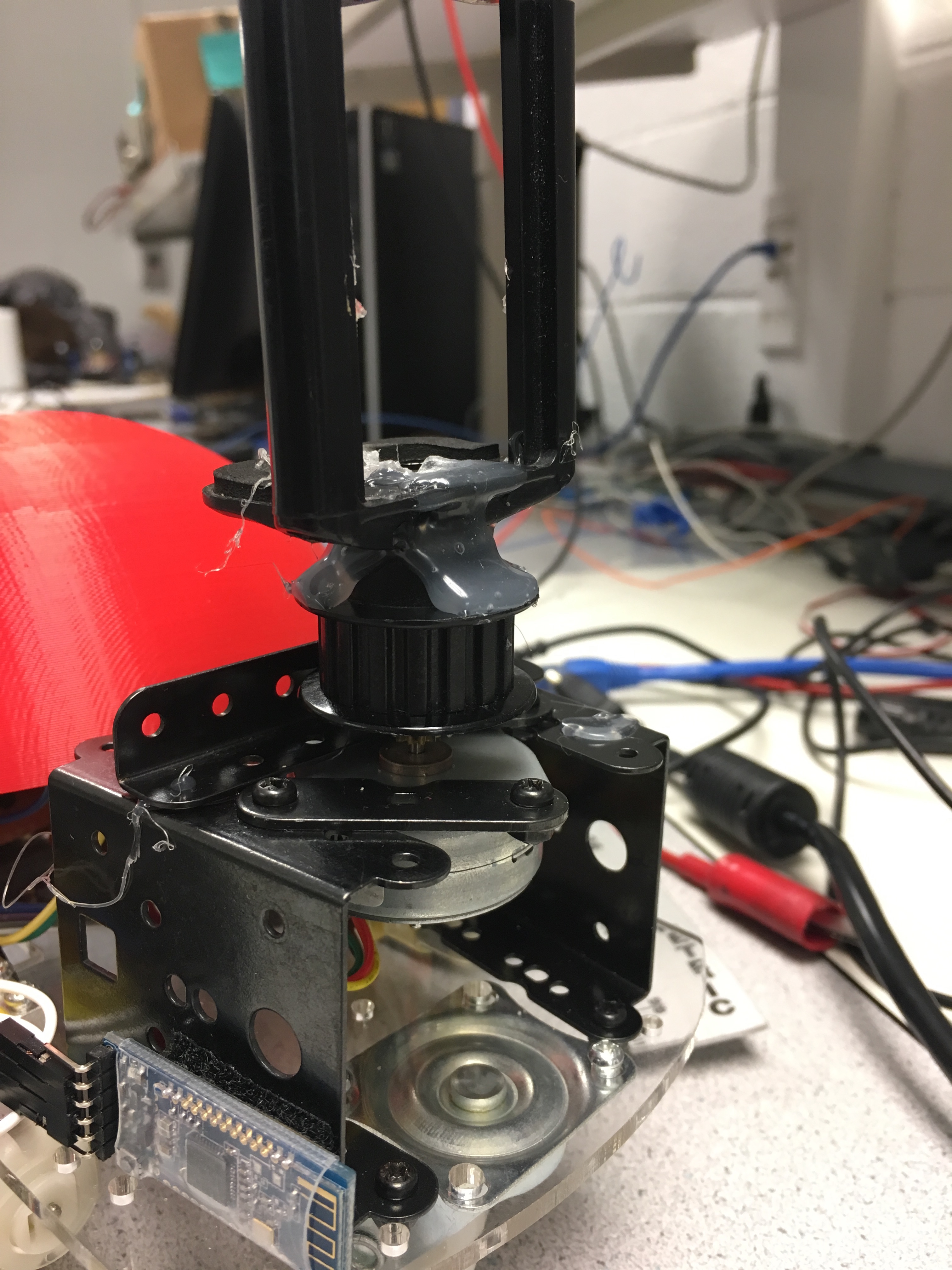
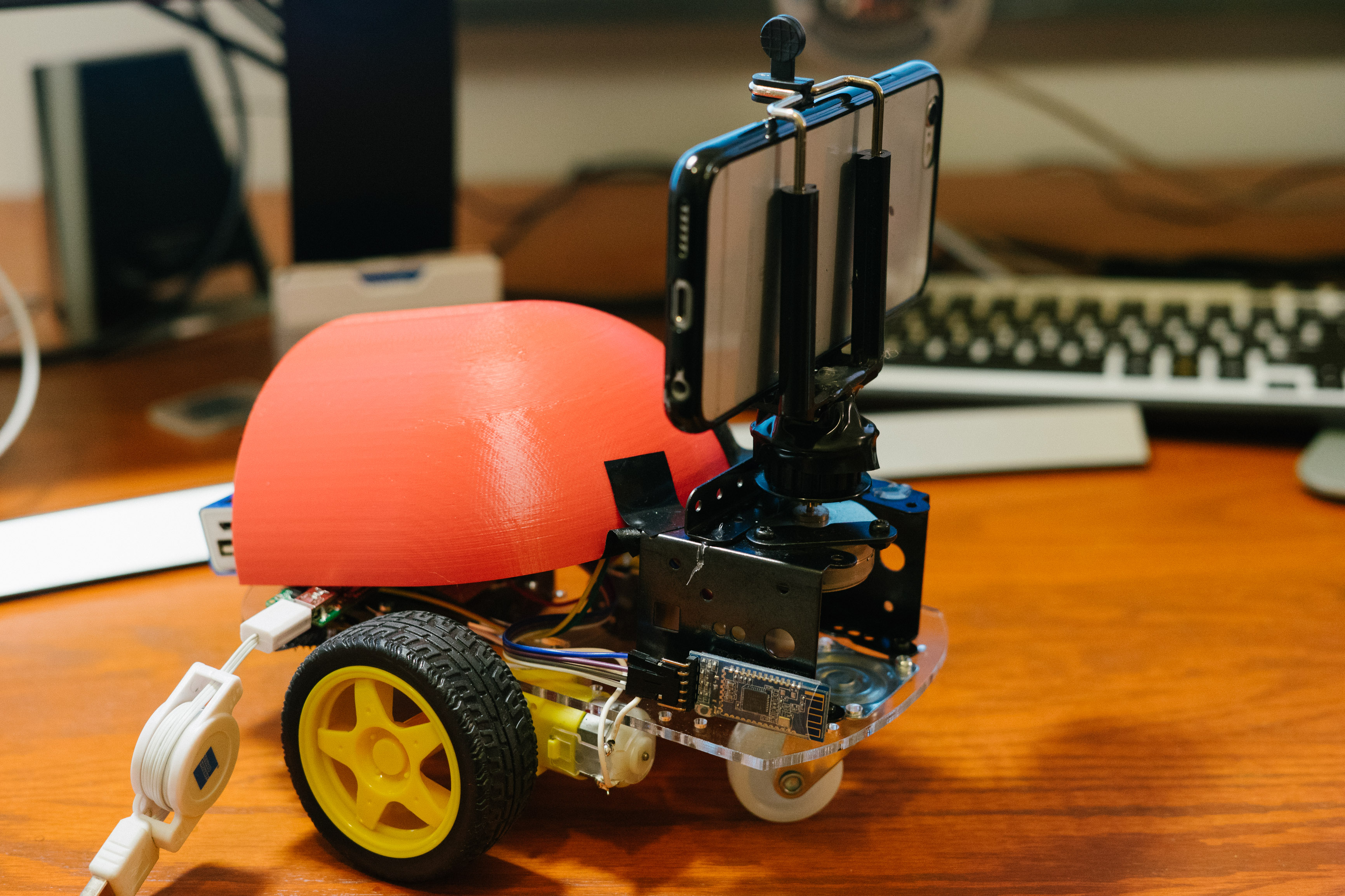
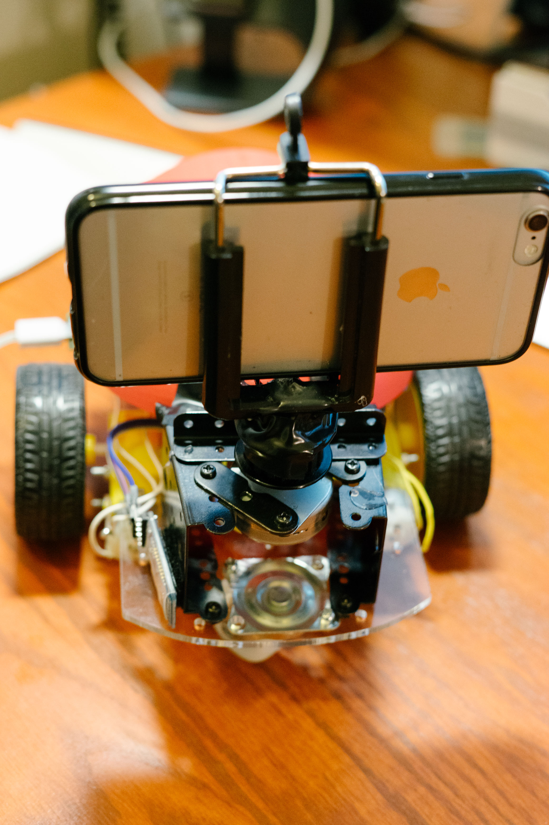
We were also able to find spare connection pieces from a spare vehicle kit in class to build up the frame of the camera-holder, and this frame screwed directly onto the chassis. Shown below is a picture of the camera frame we built. As shown, we glued an iPhone mount, which would be used to hold the iPhone so it could record video/take photos.
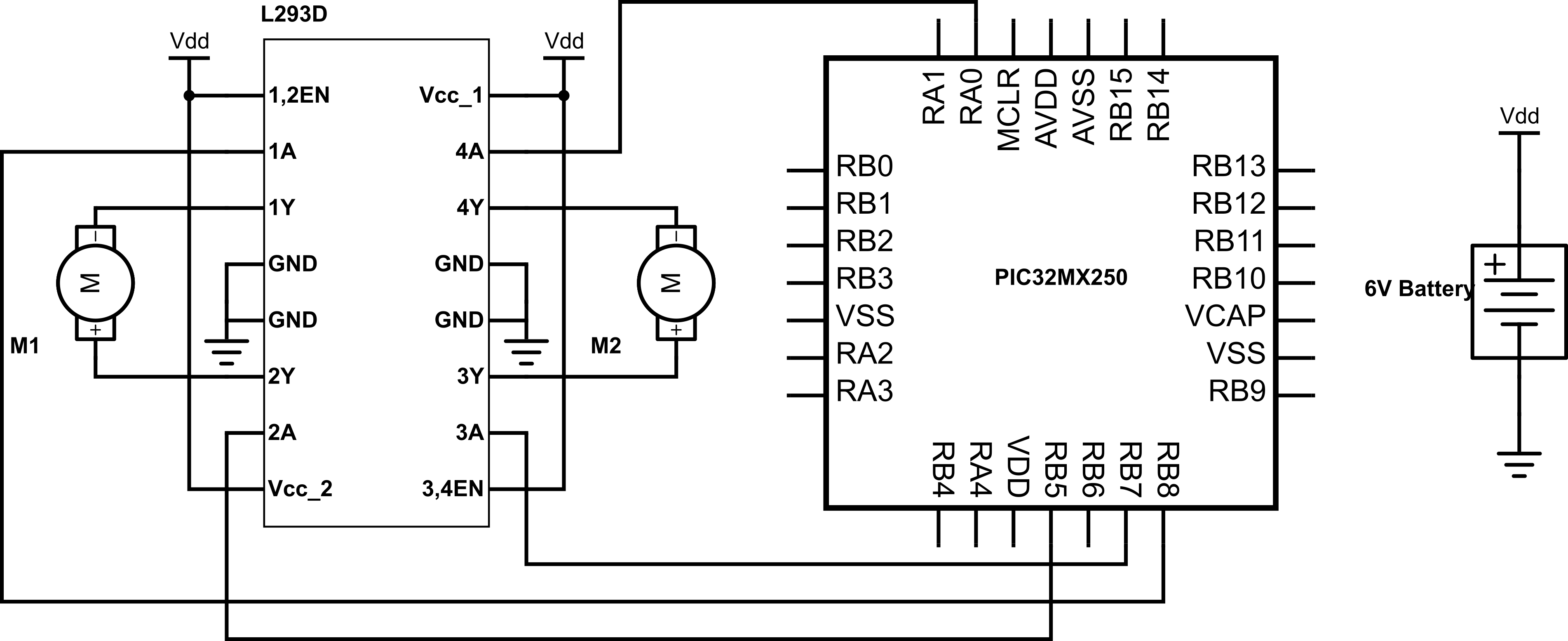
For running the DC motors, we used PWM as a control. Because these were DC motors, the required chip sent to signals to the DC motors which gave a signal to the motor to either move clockwise or counterclockwise. The A pins (1/2 and 3/4) could be conrtolled accordingly to control the motors. As found on the datasheet, having pin 2 (or 4) with logic high and pin 7 (or 10) with logic low would move the servo in the clockwise direction. Switching the high/low values would make the servos move in the counterclockwise direction. Because these corresponding functions only allowed movement with full speed, we then used PWM to control the relative speeds. Similar to the configuration which we used within Lab 4, we used a period of 10,000 timer ticks for the PWM, and after configuration and experimentation, saw that a level of 3,825 ticks was the approximate zero-speed tick number for both of the motors. We then calibrated all of the motion relative to this number.
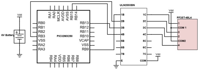
Camera rotation is actuated by a PF35T-48L4 unipolar stepper motor, shown below.
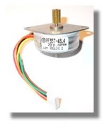
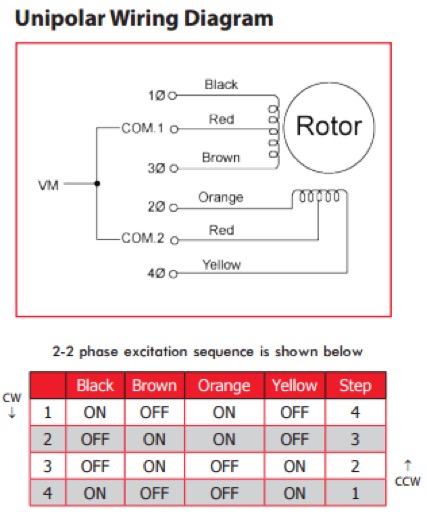
This stepper has a 48 steps, giving it a granularity of 7.5 degrees. The stepper inputs are connected to a ULN2003BN high-voltage, high-current Darlington transistor array. Pins RPB9, RPB3, RPB13, and RPB15 of the PIC32 are used as inputs the ULN2003BN. To rotate the motor, a certain phase excitation sequence of the stepper inputs must be followed. This sequence is shown in the image below.
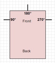
The stepper positions are mapped to absolute angles, shown in the diagram below. Through the iPhone app, the user can specify the angle that the camera should face, as well as the length of time it should take for the camera to rotate to that angle.
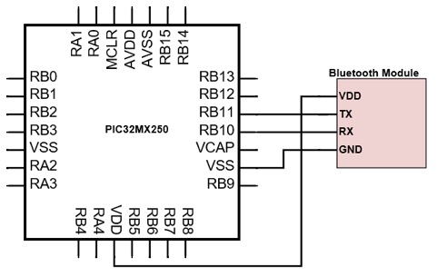
The final hardware portion involved the Bluetooth module. The PIC32 and HM10 Bluetooth chip we used communicate through UART. We picked the hm10 module (vs hc-05, hc-06) because of it's BLE abilities. we discovered apple doesn't let bluetooth 2.0 devices talk to the phone so we had to spring for a bluetooth 4 BLE model. On the PIC32, we initialize UART2, which uses pins RPB11 and RPB10 for receiving and transmitting, respectively. The RX pin of the PIC32 was connected to the TX pin of the bluetooth chip, and the TX pin of the PIC32 was connected to the RX pin of the bluetooth chip. The schematic for this is shown here.
Results
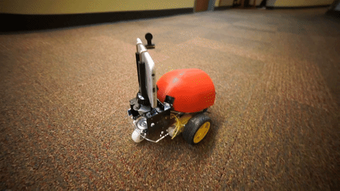
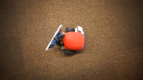
The technical aspects of the project were completed on par with our expectations. Our robot was able to traverse forwards and backwards, as well as rotate clockwise and counterclockwise in place. This allowed for freedom of motion in the xy-plane. A user can configure the robot to move on this plane in any way desired. In addition, the attached camera could rotate 360 degrees, independent of the robot platform. The camera rotation was limited in granularity by the stepper motor, which could rotate in multiples of 7.5 degrees at a time. However, this issue can be avoided by rotating the entire robot itself, which allows for an infinite range of degrees. Free mode on the robot, we found, was very accurate. When controlling the robot through the phone, we saw that the robot's movement was very swift and there were never any issues with unexpected movement. At times, due to uneven or unideal surfaces, the robot didn't go perfectly straight when the user intended it to.
The robot was highly responsive to commands from the iPhone app. We leveraged existing technology to avoid the need to create a complex communication scheme from scratch. Bluetooth is a proven close-range communication technology that provides high speed data transport.
There was no lag between when the user touches a button on the app and when the robot responds. As such, we could provide highly accurate timing in programmed mode. For rotating the stepper, timing was done on the PIC32 by changing the protothread yield times. This does not ensure precise timing, as there are no guarantees that a thread gets scheduled immediately after yielding. To optimize against these uncertainties, we programmed the hardware with efficient code and very few, short, non-blocking threads. We found that performing timing on the hardware yielded very results. The stepper was very responsive and did indeed rotate to a desired position in the specified time. Any slight inaccuracies would be unnoticeable in the recorded time lapse video. Also, for a short range device, bluetooth performed very well, being responsive at distances of up to 40 ft.
We never encountered a case where the robot continued motion beyond its instructed path. Nonetheless, we programmed an emergency stop button into the app and hardware to safely stop the robot in the case of a miscommunication.
We also believe this robot/app is very usable by the general public. Because we have an iPhone application that can be downloaded, and the robot is very modular in usage (with no detailed setup required), anyone can easily connect to the robot and control it. There is no need to run programs, or calibrate any part of the robot, which makes usage very simple.
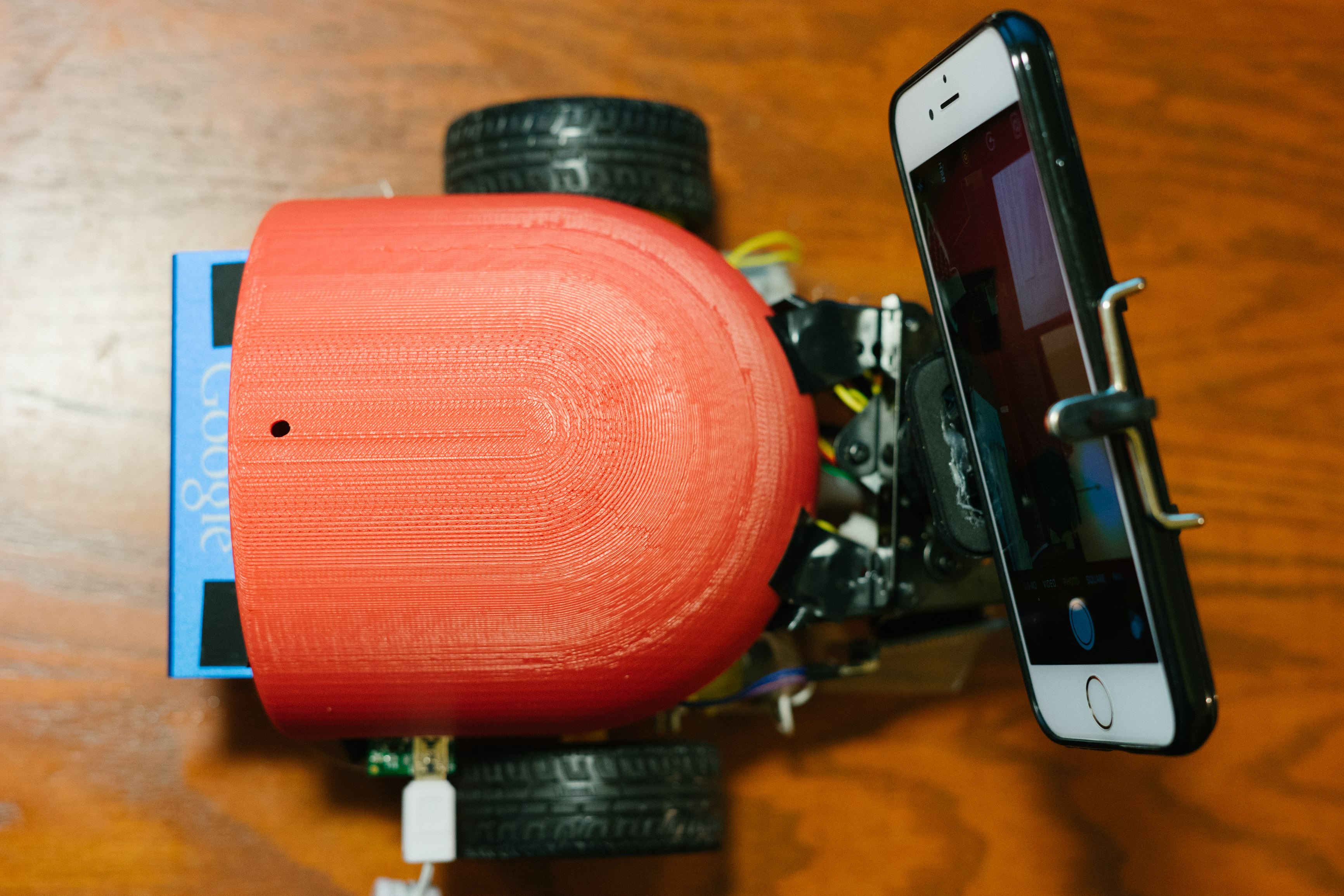
Shown below are a few pictures of our robot from different views.
Conclusion
Overall, we believed that we did a respectable job with the project, as it is a project that we could potentially use for making neat videos or timelapses (mostly Ope, the photographer but can easily be extensible to anyone). All the features we expected to be on the vehicle were implemented (as we thought up initially during the mandate). All the individual components worked as expected and there were no major issues that prevented proper usage of the project. We were also able to make the multiple modes of usage (free mode and programmed mode), which made the project much more flexible.
If we were to do the project again, however, we would definitely change many things to improve the complexity of the project and make it neater. With regards to complexity, we definitely would have tried implementing more complicated programmed instructions that would allow better control of the dolly if it were to travel in an unusual landscape. An initial thought for a UI included drawing out a path, and programming the robot to move as such. Additionally, we also had ideas of allowing for more complex camera movements (all of pitch, roll, and yaw). Finally, a lot of the final robot could have been a bit neater (though it didn't hinder functionality), and we could have solved this by either making a PCB or figuring out wiring for the entire device before soldering individual components on a circuit board.
There weren't too many standards we needed to comply with for our project. We did use bluetooth to help communicate between our iPhone and the robot, but the chip satisfies all required standards. This can similarly be said about the iPhone application side, as all development was done through official Apple software.
Intellectual Property Considerations
Through the development of the project, we believe we did not violate common rules of intellectual property or reuse protected code. All of the code on the PIC32 was written by ourselves, and was based off of work we had completed in previous labs. The code for the iPhone application was also written by us entirely.
Unfortunately, there are no patent opportunities of opportunities for publishing for this project, as camera dollies are used commonly in practice. This was our own internal project however, and is able to function off of tools built by us.
Ethics
We took a look at the IEEE code of ethics before starting our project and followed it as closely as possible. We were consistently looking at the safety aspects of our projects. We did a lot of testing of the individual components and as a whole as well. We also tested our product in multiple terrains and made it safe to handle, making sure to hide and insulate all our wires and arrange them in such a way as to prevent noise and interference between batteries and motors like using different sources of power for different components and using a common ground. In writing this report we were sure to be as honest as possible and detail any pitfalls and limitations to our knowledge so as to avoid any confusion or misrepresentation of our project. We also made sure to do a lot of research and to ask people with better technical competence when needed for parts we didn’t know how to proceed on. In all this was a project with little ethical concerns from the builder's perspective. The consumer might have to answer their own ethics questions as to where would be an acceptable place to use this device (e.g, it’s use on private property) but that is beyond our control. We’re proud to have built a safe and easily controllable device with multiple fail safes that has been tested thoroughly.
Legal
For our bluetooth scheme, we were sure to use commercially available products, which adhered to any bluetooth regulations as specified within the chip datasheet. Additionally, as specified in the previous sections, we used legal and official software (Xcode) for iPhone app development, and were able to test the application through provided certificates.
Appendix A - Release Permission
The group approves this report for inclusion on the course website.
The group approves the video for inclusion on the course youtube channel.
Appendix B - Program Listing
Our PIC32 code, written in C, can be found at the following link. The code written for the iPhone application can be found at the following link.
Appendix C - Schematics
DC Motor Schematic:
Appendix D - Cost Details
Shown below are the various purchases we made for the project. Everything else in the project (such as some of the ICs, the stepper motor, etc.) were scavenged within the lab.
| Name | Description | Cost |
| INSMA Motor Smart Robot Car Chassis | This package contained a laser-cut chassis, two DC motors, a battery pack container, and wheels. | $13.85 |
| CTYRZCH AT-09 BLE Bluetooth Module | This was the bluetooth chip we used to communicate from the PIC32 to the iPhone application. | $10.99 |
| AA Batteries | The batteries were used to power the DC motors and stepper motor. | $5.03 |
| PF35T-48L4 Unipolar Stepper Motor | This stepper motor was used to rotate the camera. The motor was found in the lab space. | $0.00 |
| ULN2003BN Chip | This is the transistor array chip (H-bridge) used to control the stepper motor. We were able to obtain a free sample from TI. | $0.00 |
| PIC32MX250F128B | Microcontroller | $5.00 |
| Solder Board | Board used to integrate the PIC32 and other components. We scavenged this in class. | $2.50 |
Appendix E - Group Task Breakdown
Shown below is the distribution of work on the project according to approximate tasks. While we did all have somewhat discrete tasks, there was plenty of cross collaboration and work done on other sections.
| Member | Tasks |
| Jason Zhang |
• Stepper Motor Functionality and Calibration - This included working through the stepper motor and making it functional. He went through many steps, first through manual usage • bluetooth Integration - This included testing the bluetooth module using UART and writing the corresponding functions to determine what commands the iPhone application specified, and routing them to actions for the PIC32. |
| Sacheth Hegde |
• Robot Construction - This included getting the robot chassis, wheels, and camera stand built together and made to be structurally sound. • DC Motor Functionality and Calibration - This included getting modularized functions for moving the vehicle, experimenting with PWM to properly rotate or move the car, and create the H-bridge circuitry (with the L293D chip) to make the DC motors functional. Calibration was also required afterwards for proper speed with weights. |
| Ope Oladipo |
• iPhone Application - This included building out the iPhone application to interface with our robot and creating the protocol to communicate (through Strings) the various actions are robot needed to perform. • bluetooth - This included properly testing the bluetooth module through UART and creating modularized functions so our robot could communicate with the iPhone. |
Appendix F - References