Lidar/Haptic Feedback Electronic Travel Aid
Aaheli Chattopadhyay (ac923) | Jun Ko (kk938) | Naomi Hess (neh54)
Lab section: Thursday 4:30 - 7:30
This project is an Electronic Travel Aid (ETA) that enables the user to navigate around objects in their path and view the profile of their surroundings.
The device delivers spatial information about a small area in front of the user via haptic feedback: range information from time-of-flight (TOF) sensors is mapped to the vibration intensity of vibration motors against the user’s skin. This device is intended to be an Electronic Travel Aid (ETA) to assist in the mobility of a visually impaired pedestrian. The sensing module contains six time-of-flight distance sensors arranged horizontally at relative angles to measure distance from the user’s hand to six points along an arc in front of him or her. The sensing module is held in the user’s head. The total angular range across the distance sensor is about 25 degrees, which gives information across a spread of one meter at one meter of distance from the sensor module. Six vibration motors convey the sensor information to the user through haptic feedback using a one-to-one mapping of sensors to vibration motors. Vibration intensity is varied through pulse-width modification (PWM). If an object is detected within range by one of the sensors, the motor corresponding to that sensor vibrates, allowing the user to identify an object’s location and general profile. Various strength of vibration are used to indicate proximity so that the user can sense the change in distance and steer away from obstruction.
The data from the six distance sensors is communicated to the PIC through a UART connection to the Arduino. The sensors are connected to the Arduino. Using I2C the sensors are able to convey information to the Arduino which then transmits it directly to the PIC. The PIC then processes the readings and scales it to a pulse width modulation (PWM) value which it output to the vibration motors. The main hardware components of the project include the TOF distance sensors and the vibration motors that are are connected to the PIC through an opto-isolator circuit. The motors create the haptic feedback interface and their intensity level varies with the proximity of the distance sensors to nearby objects. The software component consists of a thread that parses the sensor readings from the Arduino and uses a scaling technique to convert that measurement to a PWM output for the motors that corresponds to the location of a specific distance sensor.
By using touch as a substitute for visual input, the user will be able to learn to use the device to seamlessly gain information about the space in front of them which will facilitate their navigation.This device can also be used by non visually impaired humans for guidance in dark spaces as well as hearing impaired individuals who wish to receive haptic feedback in loud environments.
Electronic travel aids are a fairly popular area of assistive device research. We did not locate an ETA that used TOF sensors with haptic feedback as this device does. Our project was first inspired by a haptic feedback headband that served as a safety device by alerting the wearer to any object coming near them that they might not otherwise detect (‘Augmenting spatial awareness with Haptic Radar’). In our research we found ‘Electronic Travel Aids: New Directions for Research’, published by the National Academy of Sciences, which summarizes the typical information needs of any pedestrian. This device is not intended to replace the classic long cane in most cases because the budget and time constraints of this project do not allow it to provide a comparable amount, quality, or resolution of information. However, this device can augment the user’s experience of their environment in ways a cane cannot. The device can give the user a profile view of objects that can’t be touched or heard, such as objects behind glass. Additionally the device can assist a user when echolocation cannot provide useful information to the user, for instance in a noisy environment or for a hearing impaired user or one unpracticed in echolocation. The device can also be used in combination with other navigation techniques to provide information about objects to the sides of the user’s path or above ground level in front of the user.
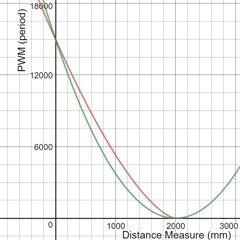
According to Poika Isokoski and Jukka Springare in their book “Haptics: Perception, Devices, Mobility, and Communication,” it is well established that using a log scale for vibration accurately depicts the perceived magnitude of vibration. For our design, we tried a similar scaling of the distance reading to the power of 1.5 and 2 to scale our distance measurements to PWM calculation.
Red = power of 1.5, Green = power of 2
We set our PWM cycle to be 40000. After testing the strength of the vibration motors, we decided to have our maximum duty cycle to be at 37.5% (period of 15000) and this was to be generated when an object was right in front of the sensor. Our maximum distance was set to be 200cm and we set our duty cycle to be 0% at that point.
Since we are using UART to read measurements sent by the Arduino and require generating a PWM signal for each of the six motors, the basic structure of our program would first be to set up all the UART pins and the output compare pins in the main function. Next, we required a protothread that would continuously read all the distance measurements sent by the Arduino and have those measurements scaled for PWM generation. Lastly, an ISR will take the scaled numbers to update the duty cycles of each motor.
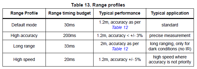
Ranging profiles of sensor from VL53L0X datasheet
There are four different ranging profiles for the VL53L0X sensor (Default, high accuracy, long range, high speed) as shown above. Each has its advantage and disadvantage and we chose to use the default mode that enables up to 120cm distance reading and 30ms timing budget with around 4% accuracy indoors depending on object reflectance. To acquire a greater viewing angle of the area in front of the user, we are taking distance measurements for all six sensors before sending the readings to the PIC. This is required for us to map the reading of each sensor and create a PWM for each of the motors. Therefore, it would take at least 180ms for the same sensor to make another measurement. Although the user will gain a wider viewing angle, the measurements for each sensors are taken slower and therefore, have slower response. If the device is being waved around fast enough, or if the user is moving very fast, the sensors would not give a very streamlined measurement of the surrounding.
The time it takes for the PIC to scale the distance readings to generate PWM is relatively small. A single line of math operation pwm_array[which_sensor] = 0.1677*pow((2000-measure),1.5) is used to convert distance to PWM on time. Timer3, which sets the PWM for 5 of the motors is updated every 1KHz. Timer2, which is the manual PWM for 1 of the motors is running at 100KHz and updates the PWM every 100 times and therefore updates the PWM the same rate as Timer3.
Our design uses a number of widely used standards such as the two communication protocols. This device uses two standardized communication protocols, I2C and UART (Universal asynchronous receiver - transmitter). The VL53L0X also contains a laser emitter that remains within Class 1 laser safety limits under all reasonably foreseeable conditions including single faults in compliance with IEC 60825-1:2014 (third edition).
Our device uses time-of-flight sensors that are becoming more and more popular for sensing distances. One of the reason behind its increased popularity is due to its speed. Semiconductor processes have also become fast enough for time-of-flight sensors to send distance information real-time. Although time-of-flight sensors are known to have errors caused by multiple reflections, we did not notice any significant errors while testing. Another design that uses the VL53L0X sensors is available on IEEE by Kiran Kanchi, which uses the sensors for depth mapping.
Our program consists of two parts. First is the code programed on the Arduino board that reads distance measurements from all six sensors and sends the information to the PIC through UART. Second part of the code is on the PIC. The PIC receives measurements from the Arduino board and performs math operation to scale the distances to an appropriate PWM duty cycle to a specified motor.
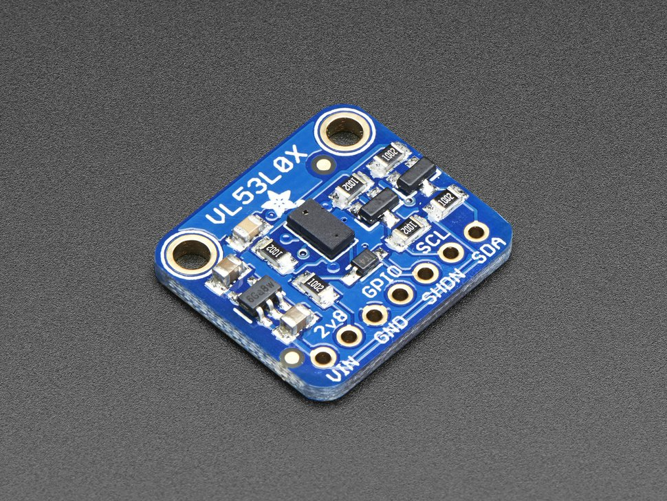
VL53L0X breakout board
Our project uses six time-of-flight laser-ranging module VL53L0X that sends the distance information to the Arduino board through I2C. The VL53L0X module shown above has seven pins (VIN, 2v8, GND, GPIO, SHDN, SCL, SDA). Of these pins, we use 5 pins to connect to the Arduino (VIN, GND, SHDN, SCL, SDA) as shown below.
The six VL53L0X boards share the same SCL, SDA pins just like regular I2C connections with one master and multiple slaves. All GND pins will be connected to the same Arduino board ground, and VIN pins will be connected to the 5V VCC from Arduino. The SHDN pins, which will be used to set new addresses for each of the sensors, will be connected to different digital I/O pins on the Arduino board. We used pins from A4 to A9 for the SHDN pins.
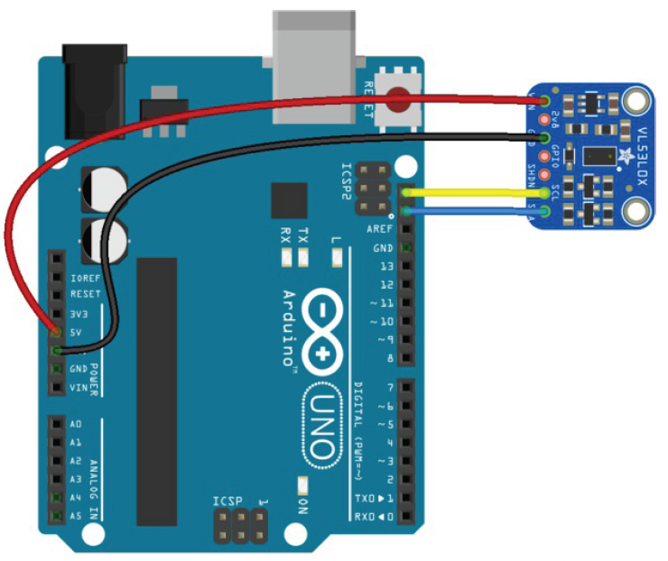
Connection for single VL53L0X sensor to Arduino board
The Arduino board will send the distance information from all the six sensors to the PIC through UART. The PIC will also be connected to 6 individual motors placed around the users arm. From the information received from the Arduino board, the PIC will generate a PWM signal for each motor. The duty cycle of the PWM signal will vary depending on the measurement readings from each sensor.
To begin reading from the VL53L0X sensor, the Polulu VL53L0X library was used. This code is a simpler version of the VL53L0X API by STMicroelectronics. The Polulu library is easier to use and has smaller storage and memory footprints on the Arduino board, which was more desirable for us as we planned to use multiple sensors. However, the library does not make use of the more advanced functionalities available on the API such as calibration of the sensor to work under a cover glass, and robust error checking. This did not pose any problems for us as we were planning to use only the default settings of the sensor, which reads distance measurements up to 120cm and do not require any further advanced functionalities of the sensor. Version 1.0.2 (2017.06.27) was used in our project.
The library includes the basic functions to initialize the sensors, set them in different modes of operation, start making measurements, and read data from the sensors. All of the sensors have a default address of 0x29. Since we want to read measurements from all six sensors, we had to manually set new addresses for the sensors. This was done by resetting all of the sensors using the SHDN pin. The SHDN pins are default high and the sensors goes into shutdown mode when the pins are pulled low. The digital I/O pins A4 to A9 were pulled low and one by one the SHDN pins were pulled high again with newly assigned address using the .setAddress() function provided from the library. We set new addresses from 0x30 to 0x35 to the six sensors.Next, we used the readRangeSingleMillimeters() function to read a single distance reading from each sensor. The measurements were sent through the UART in order (from 0x30 to 0x35).
While writing the distance sensor measurements to the pic, we separated each sensor reading by an asterisk (‘*’) to relate the reading to a specific sensor and we ended each write with an enter ‘/r’ in order to indicate to the pic that we had collected one round of readings from all 6 sensors.
We created a thread named protothread3 which spawned the GetSerialBuffer protothread. The GetSerialBuffer was taken from the “Protothreads and Timers” page of the ECE 4760 webpage. This protothread builds a string from the UART2 RX pin and stores the string in a char array term_buffer. In the function, the character “/r” is used to terminate the string and clear the term_buffer. After spawning the function, we initialize a new char array called sensor_buffer which contained the values for each distance sensor reading. In a loop, we iterated through the term buffer, accumulating all the chars in the array into sensor_buffer and once we identified a “*” character, we convert the char value in the sensor_buffer to an int , scaled the value, and stored the integer in the corresponding index of the pwm_array. Then we flushed all the contents of the sensor buffer so that it could accumulate the next sensor reading. The pwm_array held all the scaled values from the sensor readings. The scaling was 0.1677*pow((2000-measure),1.5) where measure corresponds to the integer value converted from the sensor_buffer. The reason why we structured our program in this manner was to be able to map each sensor with its designated motor. For example, the leftmost sensor, sensor1 would be mapped with the leftmost sensor on our device so that the use of the device is more intuitive and the user can have a better understanding of his/her surrounding.
Only 5 output compare channels are available on the PIC and therefore, we used all 5 channels to map sensor 2 through 6 to each motor. The timer 3 ISR was used to automatically set the PWM outputs for the 5 motors corresponding to the value in the pwm_array. For sensor1, we created a manual pwm using timer 2. A separate ISR was used to manually set and update the PWM output for the last motor.
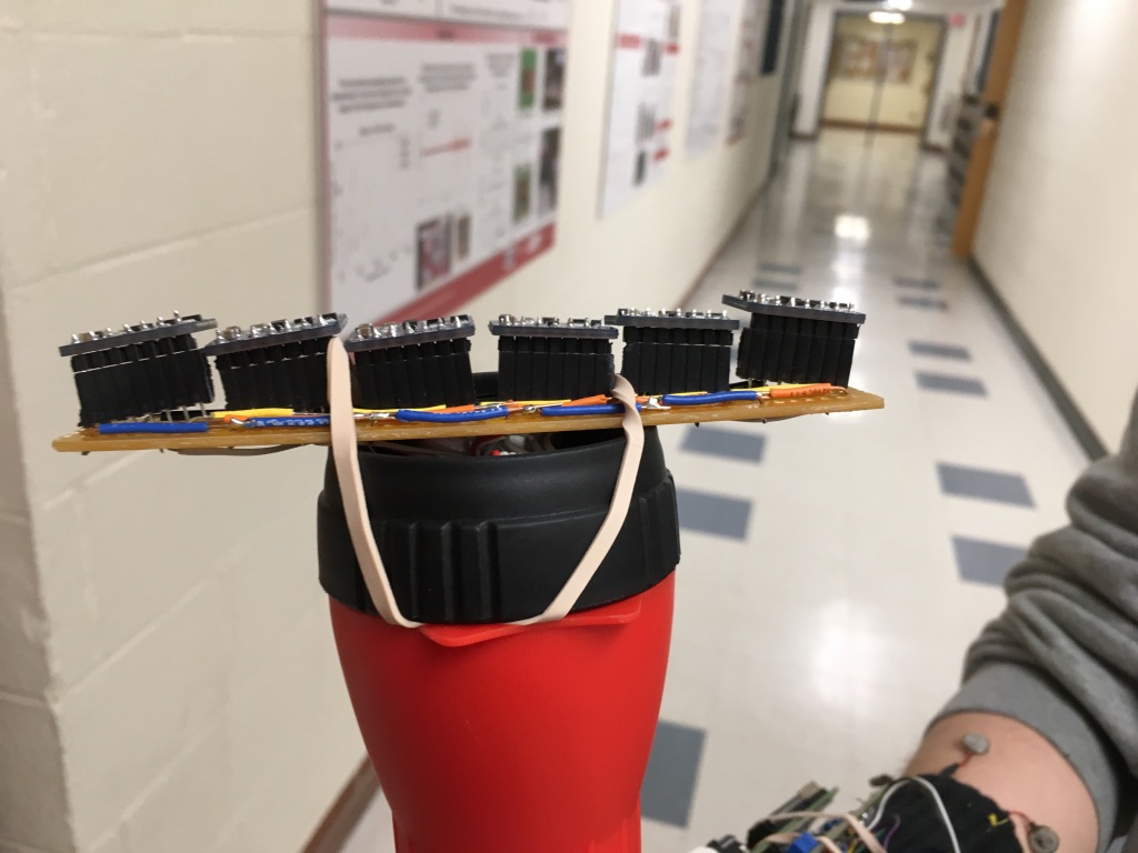
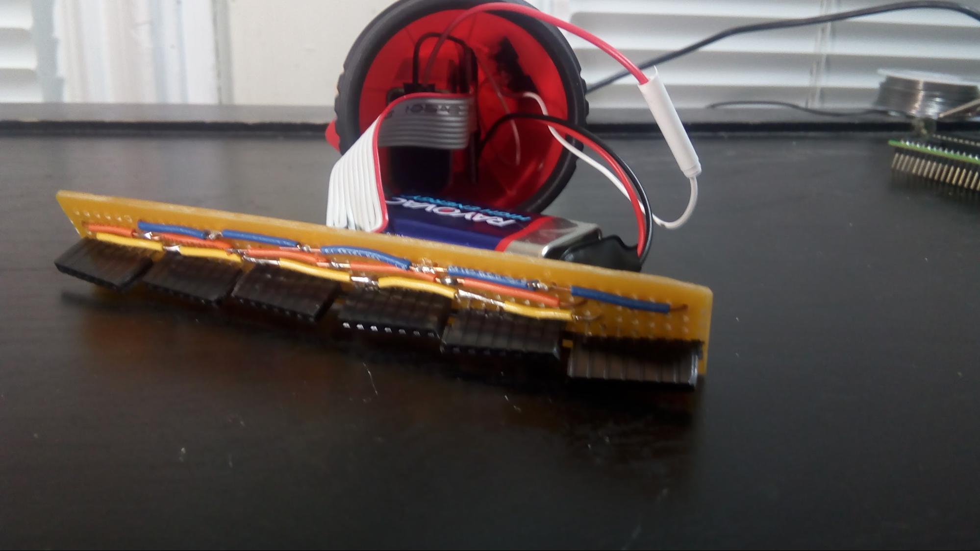
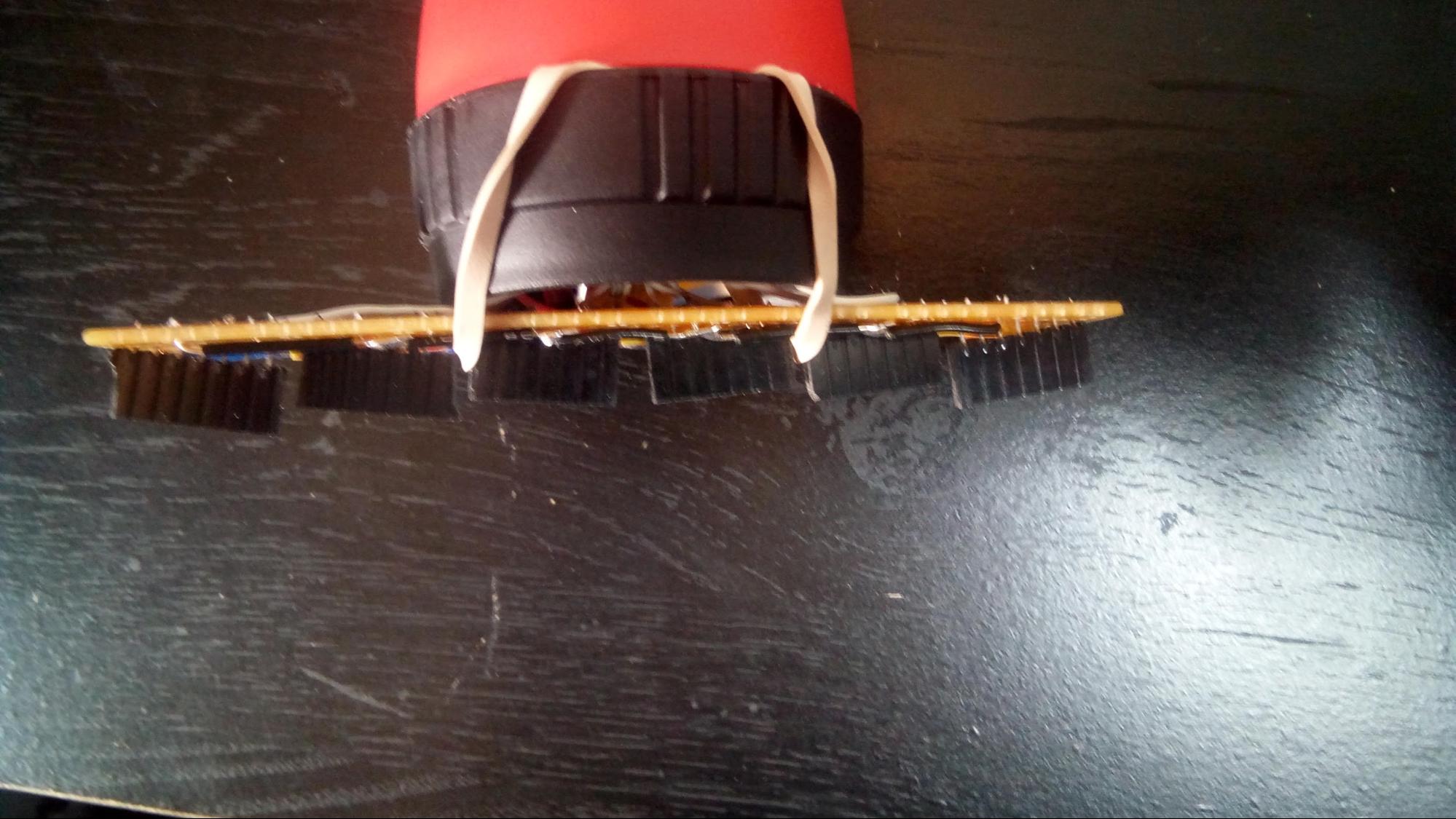
The resolution of the device was limited by budget, which allowed us to purchase six TOF sensors. The information from each sensor is mapped to a specific motor such that the rightmost sensor when the sensors are held with the flashlight button upward is mapped to the rightmost motor on the wristband and so on sequentially leftward. This creates an intuitive perception of the distance of obstructions from each of the sensors. The TOF sensors are arranged in a row on a segment of a long perfboard, mounted in header sockets soldered at certain angles. The sensors are angled to provide information over a spread of 1 meter at a distance of 1 meter from the sensors. This means the center of the sensing “cone” of each sensor is 20 centimeters apart (about a handspan) at 1 meter of distance from the sensors. The distance from one sensor to the next was known to be 0.8 inches, and the sensor array is centered between the middle two sensors. Using these dimensions, the desired angles of the TOF sensors relative to the perfboard were calculated to be, from left to right in the picture below, 12.7 degrees, 7.7 degrees, 2.6 degrees, -2.6 degrees, -7.7 degrees, and -12.7 degrees.
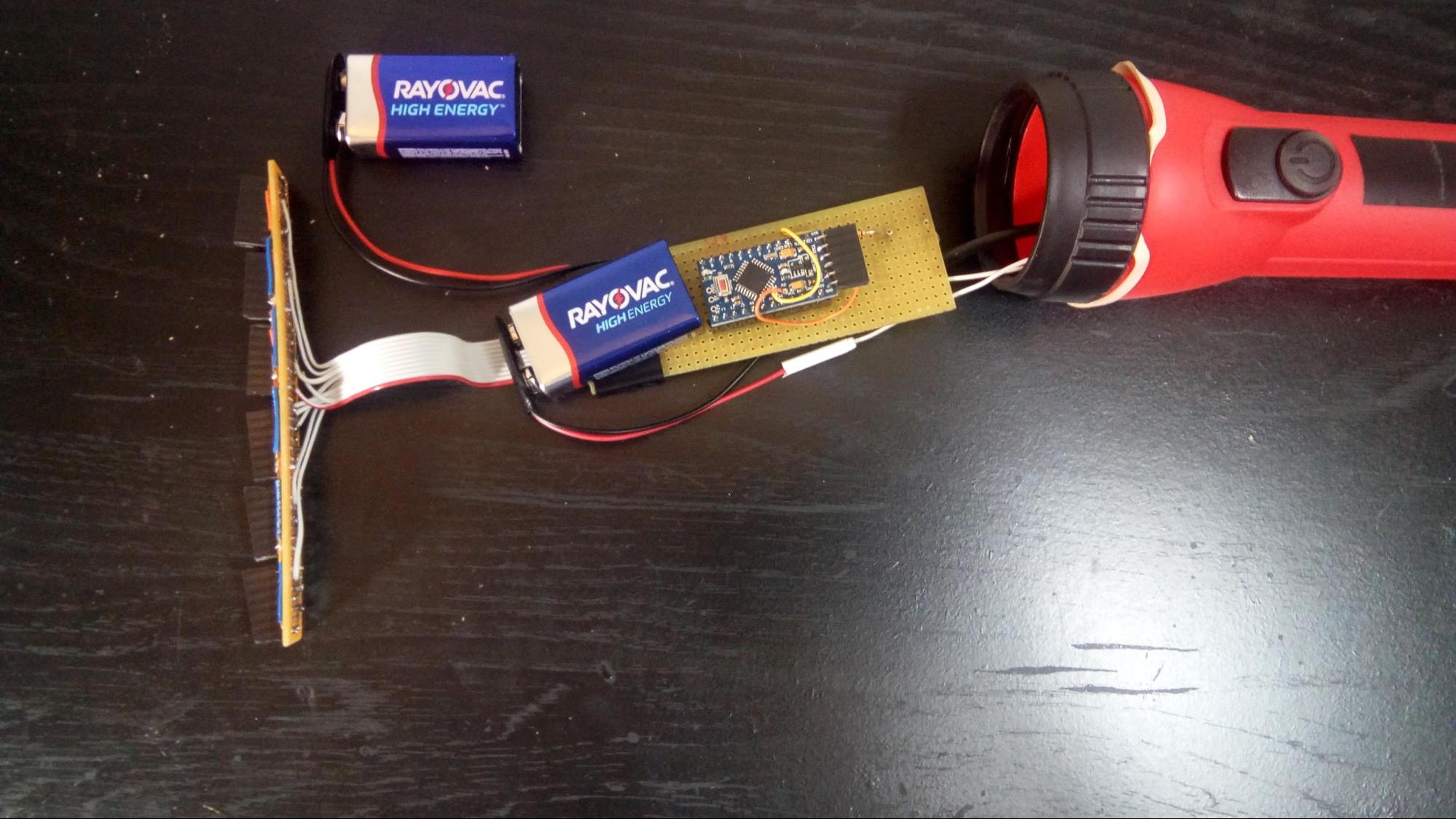
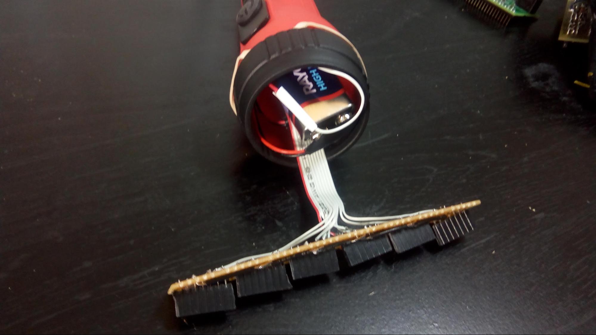
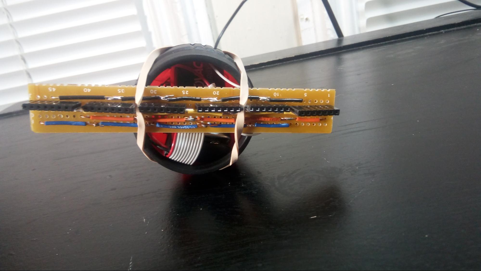
The perfboard is mounted to the front of a flashlight case using rubber bands that are held in the threads between the black plastic cap and the red handle of the case. The flashlight electronics and plastic opening cover were removed, allowing the perfboard, sensor wiring, and nine volt batteries to be accessed easily when the rubber band is unhooked.
The perfboard that fits into the flashlight is a segment of a large perfboard. The Arduino Pro Mini is mounted to this perfboard, as are the connections from the sensors to the arduino, the connections to both 9 volt batteries (and wiring to the external flashlight button, which turns the device on and off), and the connections to the cable that connects the handheld part of the device to the wristband. The cable serves as both a physical connection and an electrical connection, carrying power and ground from both 9 volt batteries and the transmit UART signal from the Arduino to the PIC32.
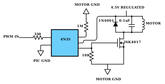
The type of motor used was a standard 3V eccentric rotating mass (ERM) motor (the coin type commonly used in cell phones). The motors required more current than could be sourced from the PIC, so a separate power source was used and the motors were optically isolated from the PIC to prevent damage to it. The opto-isolator circuit design used to isolate the motors from the PIC was taken from the ECE 4760 Lab 4 (designed by Bruce Land). A single opto-isolator circuit and its connections to the PIC are shown below. An identical opto-isolator circuit is used for each motor.
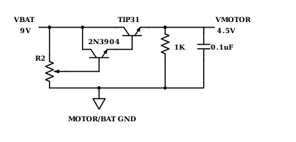
The power source used was a nine volt battery, regulated with the Darlington transistor voltage regulator circuit shown below (the output of the voltage regulator is the ‘4.5 REGULATED’ in the opto-isolator circuit).
Darlington transistor voltage regulator from 9V battery to 4.5V motor supply
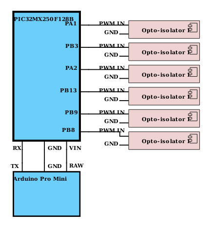
A second nine volt battery powered both the Arduino Pro Mini that was used to read from the TOF sensors and the PIC32. Both batteries were contained in the flashlight case. A cable connected the perfboard in the flashlight to the perfboard on the wristband. The cable included wires with separate power and ground from each of the batteries and the transmit UART line from the Arduino Pro Mini to the PIC32. The schematic below shows the pin mapping from the Arduino to the PIC32 and from the PIC32 to the opto-isolators.
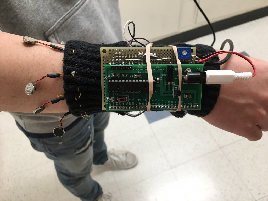
The vibration motors are attached to a wristband back from an ankle sock, with the motors arranged in a line across the top of the user’s forearm. The attachment between the motor and wristband is made by sewing the motor’s wires to the wristband. The wristband is elastic and stretches to accommodate the user’s wrist. The distance between vibration motors is about an inch when the wristband is slack, increasing up to around two inches on a larger arm. Separation by about an inch is required for the user to be able to distinguish the sensation of one motor vibrating from the next. It was found that it was easier to distinguish between motors if the motors were allowed to dangle by a short distance of wire.
The perfboard containing the opto-isolator and voltage regulation circuits and the PIC board is held to the user’s wrist with rubber bands. This system allows the wristband to fit a large range of arm sizes.
Testing was performed at each stage to ensure that all subcomponents were functional before being integrated into the device.
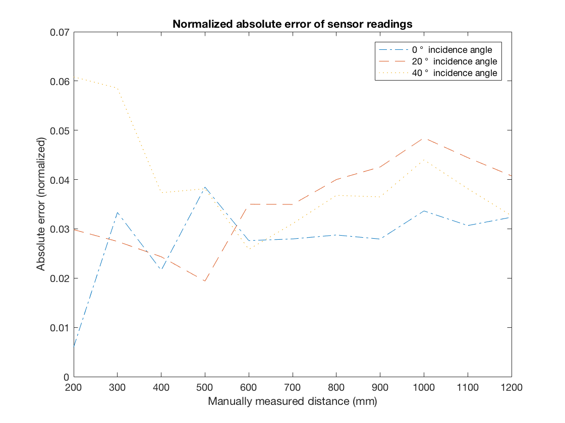
The TOF sensors were tested at varying distances and incidence angles to confirm that readings would be accurate enough to be useful. All six sensors used in the project were tested on a white painted wall in a room well-lit by sun and fluorescent lights. The distances tested were every 20 centimeters between 20 and 1200 centimeters from the wall. These tests were repeated at zero angle of incidence, 20 degrees of incidence, and 40 degrees of incidence.
Five readings were averaged together for each point and sensor. The normalized absolute error of this data is graphed below. This testing showed a mean error under 5% over all conditions tested. This is a positive result, especially considering that angles in the test conditions could not be measured with high precision, and is consistent with the manufacturer’s claim of 3~7% accuracy indoors depending on object reflectance. An uncertainty of 5% at distances less than two meters still allows plenty of warning about objects in the user’s path.
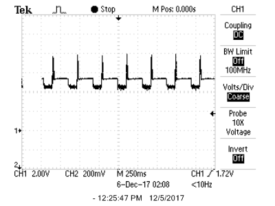
Waveforms of the PWM signals generated by the PIC were examined using an oscilloscope to ensure correct output. The opto-isolator circuits were built, examined closely against the circuit schematic by two group members, and connections were tested using a multimeter. Then the circuit was powered using a 4.5V bench power supply to ensure that no catastrophic failure or shorts would occur. After this PWM signals generated by the PIC were input to the opto-isolator circuit and the output PWM signal from the opto-isolator circuit was examined using an oscilloscope.
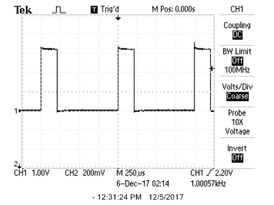
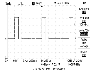
These oscilloscope captures show the 3.3V PWM signal generated by the PIC in an ISR, as discussed in the Software Design section. This was necessary as each of the six vibration motors requires an independent PWM signal and the chip used in this project, the PIC32MX250F128B, contains only five output compare units (each of which is programmed to produce a PWM signal using functions from the PIC32 peripheral libraries). These captures show two different duty cycles, approximately 20% and 15%. When examination of the waveform showed it was correct, the vibration motors themselves were tested by connecting them to the output of the opto-isolator circuit. At this stage of testing the maximum duty cycle of 37.5% was chosen. Increasing the duty cycle beyond this point can cause the motors to overheat.
This oscilloscope capture shows the output of the voltage regulator while the vibration motors are operating at a high duty cycle (sensing an object very close to the sensors). The output of the regulator is set to about 4.5V. The vibration motors draw about 200mA when all six motors are operating at maximum duty cycle (37.5%). There is a voltage spike of about 3 volts on the rising edge of the PWM. Obviously the regulator is imperfect and somewhat noisy, but it is sufficient for this application.
Product testing was conducted indoors, on a white, green, yellow, and blue tiled floor in a hallway in Phillips Hall. The hallway was lit by sunlight and fluorescent lights. Two waste baskets were placed at varying points within a fifteen foot stretch of hallway, one overturned and one upright. The user (unaware of the locations of the waste baskets) then attempted to navigate through the stretch of hallway with their eyes closed, using only the ETA. In ten tests, the user was able to successfully navigate around the objects six times. The results indicated that with more practice navigating using the device (gaining a sense of what angle to point the sensors, what speed to walk, what scanning motion to perform to gain a picture of the environment), navigating around objects would be achievable. Additionally, tuning the scaling of the sensor readings to the haptic feedback could be performed.
Additional informal testing conducted by navigating around Phillips Hall using the ETA. This testing supported the conclusion that a practiced user can navigate around most object without difficulty as long as they do not move more quickly than the environmental feedback updates - in practice, an ordinary walking pace.
We have enforced safety on our design by insulating all the wiring, closing any soldered connections with electrical tape, and protecting our batteries and circuits inside a flashlight case. We have also enabled a switch on the flashlight for the user to turn the device on and off. We have a cable connecting the flashlight to the wristband, so that if the user’s hand loses control over the flashlight, he or she will not become disconnected the device. This is especially useful for visually impaired people who may have trouble picking up the flashlight if it dropped to the floor. This device is well suited for visually impaired people who can use it to navigate around most spaces and receive sensory feedback through the wristband. Additionally, any person can use this device to help them navigate around dark spaces. An additional interesting feature of this product is that since it uses light waves near the visible spectrum, the user can use it to see through clear glass such as a window or glass wall. This is an unusual feature for an ETA. In future design, the sensors can be placed within a glassed surface for sensor protection. A limitation of our usability is that the batteries will need replacement occasionally because there are no charging feature in our design.
The design for the haptic distance sensor device was simple and robust as we were seamlessly able to communicate our distance readings to the pic which then adjusted the pwm of the motors at a rate of 1Khz. The efficiency of the transactions between the Arduino and the pic and the pic and the motors allowed us to receive consistent and accurate haptic feedback and instilled a reliability in the user who was wearing the device. In order to improve our design further, we would consider using a bluetooth module to have the Arduino communicate with the pic instead of wiring the transmission line from the Arduino directly into the pic’s receive line. This would also make our design easy to wear and allow the haptic interface to be placed on any part of the body that the user desired. Our project did not violate anyone’s intellectual property but was inspired by a patent that deals with multisensor system on a headband. However, the multisensor system described in the patent is configured to detect objects at an elevation at which it is carried on the user. The patent focuses on preventing the user from colliding with obstruction. Our focus is to help the user navigate. Our sensor system focuses on the front area of the user and attempts to detect any obstructions from floor to eye-level. Alert to the user is given by a vibration motor to indicate the location of the nearby obstruction.We have also considered the legal restrictions of the project and obeyed all standards. The VL53L0X distance sensor contains a laser emitter and corresponding drive circuitry. The laser output is designed to remain within Class 1 laser safety limits under all reasonably foreseeable conditions including single faults in compliance with IEC 60825-1:2014 (third edition).
The ultimate goal of our project is to use our knowledge in microcontrollers to create a device that will aid the visually impaired to navigate in areas with obstructions. In developing our project, we took in ethical considerations as listed in the IEEE Code of Ethics. We tried to create an affordable and easy to use device that can safely and reliably help the visually impaired. We wished to create a device that is more robust than the walking stick that can further enhance the safety of the visually impaired. In addition, many visually impaired people also suffer from hearing loss. To take this into account, we incorporated a haptic design that gives an intuitive description of the area in front. In using time-of-flight sensors, we used the VL53L0X sensors that outputs laser within Class-1 safety limit that is in compliance with IEC-60825-1:2014 (third edition). We abided by the manufacturer’s laser safety considerations for safe use of our device and to avoid harming others. In order to confirm that our design works as intended, we tested our device multiple times in different surroundings. As our device can have direct relation with the safety of the user, we did not tamper with our results and stated the limitations of our project. We are open to any suggestions that can improve our project.
The group approves this report for inclusion on the course website. The group approves the video for inclusion on the course youtube channel.
Arduino Code (Read from sensors and send information to PIC)
PIC32 Code (Read measurement readings, scale values, generate PWM)
Darlington transistor voltage regulator
Opto-isolator circuit design for each motor
Pin map
Aaheli set up the uart connection between the Arduino and the pic, wrote code to parse the uart message and convert it into a pwm value, and assembled the distance sensors and Arduino Pro Mini on the perfboard. Aaheli wrote the introduction, software design, and conclusion sections of the final report and formatted the website.
Jun assembled the connections for the sensors to the Arduino and the connections for Arduino to the PIC. Wrote the Arduino code to read from the sensors. Wrote code for the pic to read from UART, scale the distance measurements to PWM values, and set up ISR for manual PWM. Jun wrote the high level design, software design, and the ethical considerations section.
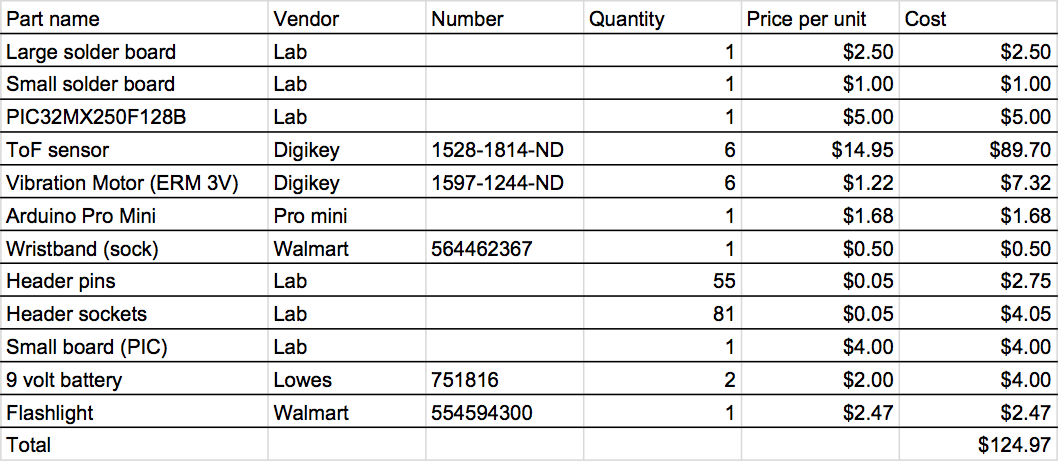
Naomi assembled the vibration motor circuits and set up the PWM channels for each motor, developed the voltage regulator circuit for the motors, conducted the physical integration of the system and, along with Jun and Aaheli, coded the PIC to receive UART and scale the distance measurements to PWM values. Naomi wrote the hardware design, the testing and results section, compiled the bill of materials, and wrote part of the high level design section.
VL53L0X (ST Microelectronics)
www.st.com/resource/en/datasheet/vl53l0x.pdf
Adafruit VL53L0X Breakout (Adafruit)
https://learn.adafruit.com/adafruit-vl53l0x-micro-lidar-distance-sensor-breakout/overview
2N3904 (ST Microelectronics)
www.mouser.com/ds/2/149/2N3904-82270.pdf
TIP31 (ST Microelectronics)
www.st.com/resource/en/datasheet/tip31c.pdf
Polulu Arduino library for VL53L0X sensor
https://github.com/pololu/vl53l0x-arduino
PIC32 protothread code for UART
http://people.ece.cornell.edu/land/courses/ece4760/PIC32/ProtoThreads/Semaphore_alternating_input.c
1. Poika Isokoski, Jukka Springare, “Haptics: Perception, Devices, Mobility, and Communication: 8th,” 2012
2. Cassinelli Alvaro, Reynolds Carson and Ishikawa Masatoshi : Augmenting spatial awareness with Haptic Radar, Tenth International Symposium on Wearable Computers(ISWC) (Montreux, 2006.10.11-14)
3. National Research Council (US) Working Group on Mobility Aids for the Visually Impaired and Blind. Electronic Travel AIDS: New Directions for Research. Washington (DC): National Academies Press (US); 1986. Chapter 6, THE TECHNOLOGY OF ELECTRONIC TRAVEL AIDS. Available from: https://www.ncbi.nlm.nih.gov/books/NBK218025/
4. Kiran Kanchi, “Explorer,” IEEE
https://transmitter.ieee.org/makerproject/view/37299