Alex Huang (ah 757), Evan Mok (etm46), Eric Cole (erc84)
The goal of this project is to develop an electrooculography (EOG) system that can record potentials across a user’s eyes, and use the resulting signal to control a simple video game.
An electrooculograph is a device that measures the standing potential across the human eye. In this project, we will use silver-plated electrodes to record the EOG signal from both eyes and compare the difference between the two potentials. This difference changes when the user moves his or her eyes left or right, and we will track such movement by amplifying this voltage difference and using an ADC (analog-to-digital converter) to interpret the EOG signal as a digital value. The user will then move his or her eyes left and right to control the position of a cursor on an LCD screen and avoid oncoming obstacles.
Brain-machine interface systems have many implications in medicine, treating paralysis by allowing control of prosthetic limbs. With this project, we hoped to explore ways that a biomedical recording system could be used to circumvent such limitations and control a digital device. We initially began with the idea of developing an electroencephalogram (EEG) to directly record neural signals from the scalp. However, such a project proved difficult for a number of reasons: such a recording requires significant amplification due to heavy dissipation through the skull, and there are many safety concerns with placing electrodes directly on the scalp for such a recording. Both of these safety concerns will be discussed later.
After exploring other types of biomedical signals, we arrived at the idea of an EOG, as it alleviates the above problems - the potential at the eye is closer to the surface and easier to record, and presents less of a safety hazard. We hope that this project raises awareness of new, innovative ways that technology can be applied to biomedical problems.
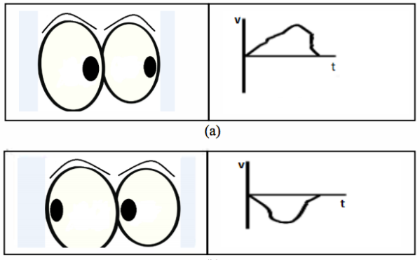
Electrooculography (EOG/E.O.G.) is a technique for measuring the corneo-retinal standing potential that exists between the front and the back of the human eye. To measure eye movement, we placed an electrode at the outside of each eye, with a third electrode above one of the eyes as a ground reference. As the eye moves from center position toward one of the two electrodes, this electrode experiences a positive voltage due to proximity with the positively charged side of the retina. When the eye moves, this potential decreases. When the user looks at the center of his or her field of vision, each eye is equidistant from the electrodes and two measured potentials are approximately equal. Upon looking left or right, one potential decreases as the other increases, in proportion with eye movement. This is demonstrated in the figure below.
In the lab, we use silver chloride electrodes to transduce a biological potential into an electrical potential. Electrical potentials in biology are created by transfer of ions - primarily Na+, K+, Cl-, and Ca2+. Potentials in electronic devices are generated by electrons. The silver chloride electrode allows one type of potential to be converted into the other using an Ag+/AgCl half-cell with the following chemical reaction:
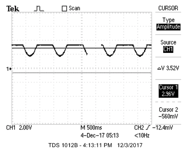
When an electrode is attached at the eye, this reaction reaches an equilibrium so that the electrode potential matches the potential at the skin. For an EOG, this potential is typically about a few millivolts. Another picture of a typical EOG signal is shown.
The voltage observed at the eye can be thought of as a very low-frequency AC signal (a DC with some drift due to instability of the electrodes), with some noise at a frequency of about 50 Hz.
It is significant to note that using electrodes to record presents a significant safety hazard. If a DC power supply is used improperly, a powerful driving force can cause this reaction can proceed to equilibrium in the opposite direction, so that the recording circuit influences the potential at the user’s eye. This can disrupt ion concentrations at the electrode interface and cause serious medical problems. Therefore a great deal of care must be taken to electrically isolate our entire system while recording from a user’s eyes.
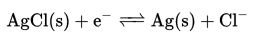
This block diagram shows an overview of the components necessary for our project. The raw EOG recording must go through extensive amplification and filtering to be converted into a voltage appropriate for processing in the PIC32. This is done with a multi-stage differential amplifier circuit, with power supply being provided by a battery circuit. The microcontroller records this value from an analog-to-digital converter and runs the game software, which has two outputs: the visual component of the game on an LCD display, and a sound output via a digital-to-analog converter that is sent to a speaker. The user reacts to the display while playing the game, which results in a change in the electrode signal that controls the game.
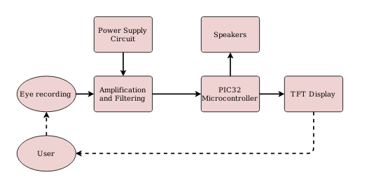
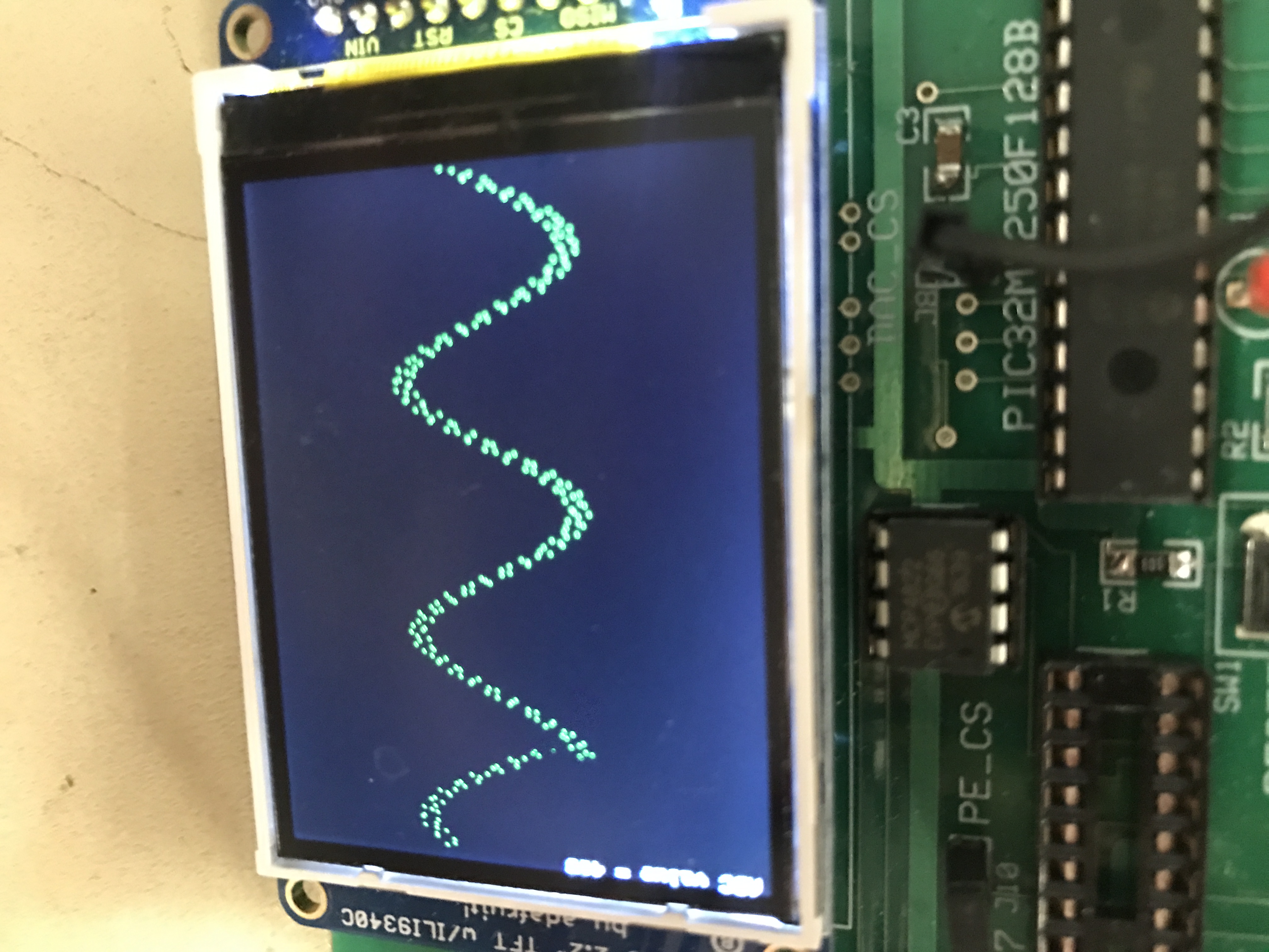
A picture of the game screen is shown below:
The user controls the paddle on the left, which switches between one of three locations when he or she looks left, right, or center. The bars move from the right side of the screen to the left at a constant velocity, and the user moves the paddle to avoid them.
Next to the paddle, three values are are printed to the screen. One is the score, which increments by 1 every time a bar is successfully avoided. The second is the value of the ADC, a useful tool for bug-checking, and the third is the time that the game has been running (in seconds). When the user does not successfully avoid an oncoming bar, the game ends and a “game over” message is displayed. The game also plays a sound every time a bar is avoided, and plays a different sound at game over.
As described earlier, the potential difference between the two eyes can be approximately 1-3 mV. With the appropriate ADC parameters, the PIC32 microcontroller board’s built-in ADC can only accept a voltage between 0 and 3.3 V. Therefore a significant portion of this project requires a high-gain amplification circuit that can measure the difference between the two eye inputs, filter out noise, and scale the potential to a magnitude appropriate for the ADC. In addition, electrical safety for such a project is paramount. Therefore the circuit must be completely electrically isolated from DC power supplies.
Shown below is a diagram of the complete circuit.
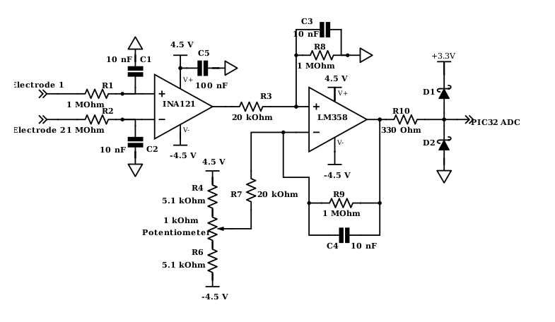
Our circuit has three important stages:
1) Differential amplifier stage: the two electrode signals are fed into a differential amplifier, an operational amplifier circuit that eliminates common components to the signal while amplifying the difference between them. This is the fundamental unit that allows for this comparison between eye voltage signals.
2) Balanced subtractor stage: this circuit amplifies the output of the differential amplifier, for a total gain to produce a voltage range appropriate for the ADC. In addition, the output of the differential amplifier is centered at an arbitrary DC offset and swings between positive and negative voltages, whereas the ADC requires an input between 0 and 3.3 V. This stage uses a manually set voltage offset input to center the signal produced by the differential amplifier at about 1.6 V.
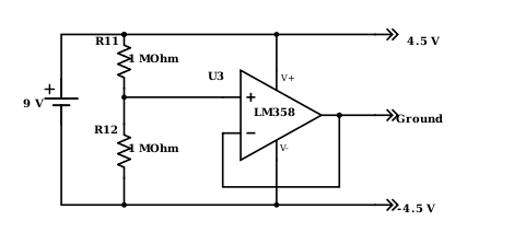
3) Power supply stage: This circuit uses a 9 V battery and a unity-gain operational amplifier to establish a power line at 4.5 V, a ground line at 0, and a -Vdd line at -4.5 V. This configuration is used to power the two stages above.
Protothreads
The code for this lab was all written in C and programmed onto the PIC32. In order to develop robust and efficient code, we heavily relied upon Protothreads, written by Adam Dunkels. Protothreads is an open source library for C that implements a lightweight, stackless threading system to organize concurrent processes running in software. Such a library allows us to organize our software into different processes and functions, without having to worry about implementing details of scheduling and memory management. For more information on Protothreads and to download the library, visit Adam Dunkels’ page:
http://dunkels.com/adam/pt/index.html
Oscilloscope Design
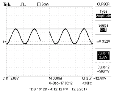
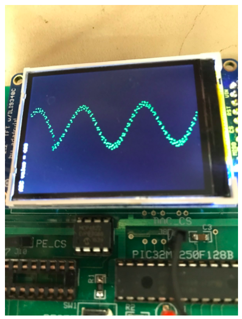
Due to safety concerns, we cannot use an oscilloscope to test voltage signals while someone is using the project. Therefore we developed our own implementation of an oscilloscope on the TFT LCD screen. This code configures the ADC and continuously samples the ADC value at a frequency of 125 Hz, displaying two seconds of the amplified input signal across the width of the screen. The height of the screen represents the range of the ADC (between 0 and 3.3 volts). A picture of an example recording is shown below, using a sinusoidal input from a function generator.
The implementation is fairly simple and only relies on one continuously running thread, which after setup reads the ADC value and performs a print to the TFT display on every iteration.
Game Software
Our game implementation uses three threads:
1) A timer thread. This thread runs once a second, incrementing the system timer that counts the game time and refreshing the values that are printed to the screen. It also prints the game over screen when the condition is enabled, and plays the game over sound.
2) A controller thread: This thread runs every 8 milliseconds and reads the ADC value to determine the new position of the paddle.
3) A dynamics thread: This thread stores information about the approaching obstacles, spawning them from the right side of the screen and updating their locations every iteration. It also detects collisions, updating the score when the user successfully avoids an obstacle or initiating game over.
Prior to scheduling, the game code also performs necessary setup for the ADC, SPI to interface between the DAC and the PIC32, DMA to generate sounds, and initiation functions to set up ProtoThreads for the above processes.
A set of standards for electrooculography is given by the ISCEV - the International Society for Clinical Electrophysiology of Vision. A paper describing these standards is given here:
https://www.ncbi.nlm.nih.gov/pmc/articles/PMC1820752/
Pupils: Apply dilating drops to the user’s pupils before beginning recording.
Electrodes: After suitable skin preparation, place small recording electrodes, close to the canthi of each eye. Connect the electrodes from each eye to separate channels of a differential amplifier. The ‘ground’ electrode can be placed on the forehead.
Amplifier: This should have a band pass of either 0 (DC) to 30 Hz, or 0.1 to 30 Hz, to provide recordings of the saccades which appear as square waves.
Pre-preparation: The test subject should be in stable indoor lighting for as long as possible before the test, and should not be exposed to any large changes in lighting (lighter/darker) during this period, such as indirect ophthalmoscopy. As near as is practical, the pre-test light exposure should be the same for all test subjects.
Preparing the test subject: Explain the procedure including, ‘chin/head on rest/restraint in stimulator, 15 min dark, 15 min light, fixation lights alternate in simple rhythmic manner, for 10 s each minute, when lights change, move eyes in single sweep to next one, do not turn head, do not anticipate the changes’. Practice the procedure with the recording system on and coach the subject if there is head movement, overshoot, stepping, or anticipation.
Measure the amplitude of the EOG: Taking care to remove the effects of overshoot and stepped saccades, measure the EOG amplitude in μV, either manually or by a computer algorithm. Calculate the average of the amplitudes in each 10 s trial.
Some of these standards are highly specific to medical applications of EOG recording and are meant to obtain accurate recordings for diagnosis. These aspects of the proposed standards are not completely relevant to our particular project, as we base our control of the game on thresholds in the amplified voltage signal so we do not need to be entirely accurate. However, safety concerns are still of utmost importance.
We did not use dilating drops before recording, but we adhered fairly well to the other standards. Our electrode arrangement was exactly as specified, using a ground electrode on the forehead. We did not use a bandpass filter, but we did use a low-pass filter that approximately fell on the range specified. The lab environment provided a very stable lighting source, and we made sure to coach our user and make instructions clear during calibration and before beginning the game. Our circuit contained several mechanisms to avoid overshooting such as our Schottky diode system.
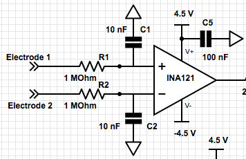
The main component of our differential amplifier stage is the Texas Instruments INA121, a differential amplifier integrated circuit. The purpose of a differential amplifier is to amplify the difference between two voltage inputs, while eliminating the common component between them. We chose the INA121 because it is cheap and has a very high common mode rejection ratio (the amount by which the amplifier attenuates the common signal between inputs - about 100 dB at a gain of 100) without any substantial efficiency drawbacks. A data sheet can be found here:
http://www.ti.com/lit/ds/sbos078/sbos078.pdf
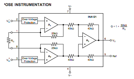
Here is a pin diagram for the circuit. Pins 7 and 4, the V+ and V- pins, are connected to +4.5 V and - 4.5 V as provided by our battery circuit (to be shown in more detail later) to power the amplifier. Pin 5, the reference, is connected to ground. Rg, connected between pins 1 and 8, is a gain resistor whose value determines the gain between the differential input and the amp’s output. Pins 2 and 3 are connected to our electrode inputs.
Before the connection to the amplifier input, the two electrode signals are connected to two low-pass filters (given by R1/C1 and R2/C2). The time constant for this filter is given by:
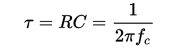
Here, the time constant is 0.01 seconds, and the cutoff frequency fc is 15.9 Hz. As discussed earlier, the electrode signals contain noise at approximately 50 Hz. This noise is also not necessarily attenuated by the differential amplifier, as it is random rather than coupled between the two electrodes. These filters are necessary to remove such noise at the input, while passing the essential DC component that results from the difference in eye position between the two recordings. These recordings will also have a frequency component when the user moves his or her eyes. However, the game does not require eye movement frequency as high as 16 Hz (nor is this easy), so this filter value is appropriate for eliminating noise while passing all the necessary signals to operate the game.
We chose an Rg value of 2.8 kΩ, for a differential gain of 17.7. The gain equation for the circuit is shown above:

This gain is not nearly enough to amplify the signal on its own (a 2 mV difference will yield an output of only ~35 mV). However, the amplifier becomes less stable when smaller resistors are used for much higher gain. We will use the second stage of the circuit to increase the gain.
An additional note - the 4.5 V power input to the INA121 is also connected to ground via a 100 nF capacitor. This is to reduce high-frequency noise from our battery power supply, which prior to this addition was shown to be slightly unstable.
The balanced subtractor stage has two purposes. First, it provides a second voltage gain to further amplify the signal from the first stage. However, having just an operational amplifier for high gain at the second stage would not be appropriate.
The first stage amplifies a difference between the electrode inputs in both DC and AC components. This gain will be the same for both signal types, but the original signal’s magnitude may not be. It is expected that the DC difference between the eyes when holding still will be greater than the AC component that results from moving one’s eyes. Assuming 20 mV offset and 1 mVpp swing from the eyes, the expected output from the two stages will be 20V offset with 1Vpp (1000x gain). This is too high to be captured by the ADC, which can only read values from 0 - 3.3V. The second purpose of the balanced subtractor is to use a manual DC voltage offset value to negate the high gain that would appear in the DC offset and cause railing, while maintaining the high AC gain. Specifically, we will manually set the Voffset to a value that changes the DC component at the output so that both the DC and AC signals satisfy the range of the ADC. For example, if the output of the first stage amplifier was 400 mV offset with 20 mVpp swing (20x gain), the offset would need to be set slightly above 400 mV. Note that the offset should not fully cancel out the offset, since the voltage swing going into the ADC must be positive at all times (ADC can only capture positive values).
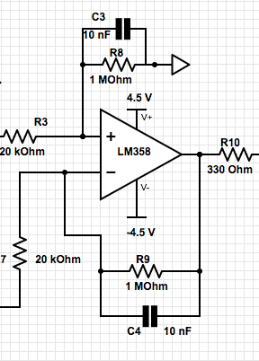
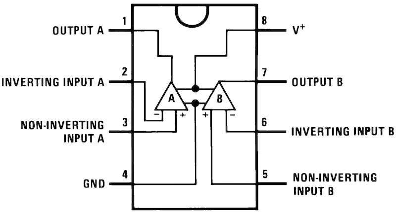
The primary component of the second circuit stage is a Texas Instruments LM358 operational amplifier. The data sheet can be found here:
http://www.ti.com/lit/ds/symlink/lm158-n.pdf
Our non-inverting input at pin 3 is the amplified output from the INA121 (wired through a 20 kΩ resistor). The inverting input is the DC voltage offset, which we created using a potentiometer (described below). The amplifier is powered by +4.5 V and -4.5 V.
Two more filters are connected at each input with the same time constant calculated earlier of 0.01 seconds. These should be included again because, while 50 Hz noise was attenuated by the first set of filters, the differential amplifier stage can also amplify this noise after attenuation. The second set of filters provides another stage of attenuation for higher frequency noise, negating any amplification effects from the first stage.
In addition to providing filtering, the 1 MOhm resistor connecting the output and inverting input is necessary to provide gain for the amplifier. The gain formula is given as:

Z|| is the 1 MOhm resistor in parallel with the capacitor, and R is the 20 kOhm resistor at the inverting input. The expected gain of this amplifying stage is 50, making the total gain across both stages 885.
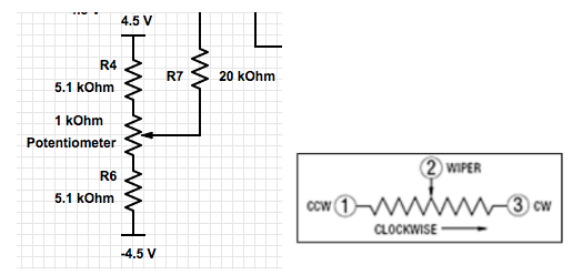
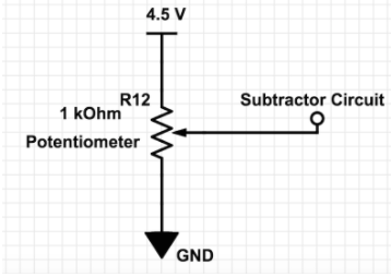
The value of Voffset was determined manually using a potentiometer. We used the following voltage divider circuit to produce a variable voltage appropriate for the amplifier:
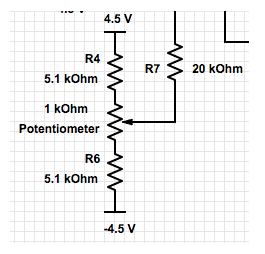
Changing the value of the potentiometer will change the value of the offset according to the variable resistance value. The offset at the output can be determined by the following equation:
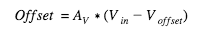
Recall that AV = 50 (approximately). The desired output of the second stage is 1650 mV (halfway between 0 and 3.3 volts, the range of the ADC). The output DC component is effectively the difference between the input signal and the manual offset, scaled by the gain of the amplifier. Given the gain of the second stage, the desired offset should be 33mV + offset from first stage. Again, assuming that the input of the second stage is 400 mV offset with 20 mVpp swing, the desired offset should be +/- 433mV exactly. The next step after determining this range of expected values is to create a voltage divider so that the potentiometer can be used to produce a voltage at approximately the same range of values.
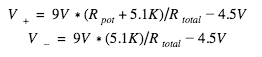
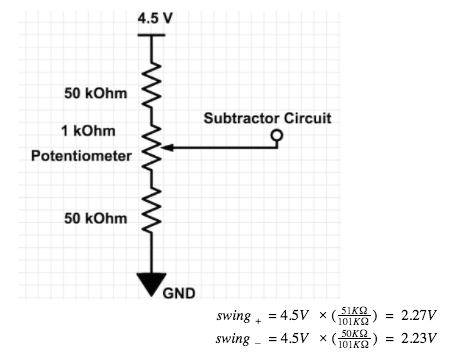
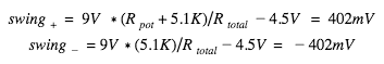
The voltage drop across the potentiometer in a voltage divider is given as Vapplied*Rpot/Rtotal ,where Vapplied = 9V. For our divider, we set our 1 kΩ potentiometer in series with two 5.1 kΩ resistors to reach a offset swing of +/- 450 mV. Below shows the two equations used to calculate the maximum and minimum swings for the offset.
Finally, the output of this amplifier is a signal with appropriate magnitudes for both the DC and AC components. In other words, it is centered at the middle of the ADC range (about 1.6 V) and swings by about 1 V.
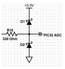
To protect the ADC pin, we included one final circuit component. First, a 330 Ohm resistor is used to protect the pin at the ADC. This resistor is followed by two Schottky diodes. The purpose of these two diodes is to forcibly restrict the range of the voltage to between 0 and 3.3 V. The Schottky diode passes a large current when a positive voltage is applied (a condition called forward bias). When the voltage output is below 3.3 V, D1 essentially has no effect on the circuit. However, when the output becomes greater than 3.3 V, D1 is placed into forward bias and passes a very high current so that the output voltage rails to +3.3 V. Similarly, D2 passes a current when the output swings below 0 V, forcing a rail at ground. This system restricts the output voltage to the range of the ADC, protecting the pin.
Note here that a voltage of 3.3 V is supplied to the diode. This is a power supply provided by the microcontroller itself rather than the battery circuit. The microcontroller ground was tied to the same line as the battery’s ground, so that this 3.3 V supply has a proper value relative to the voltages generated by the amplifying circuit.
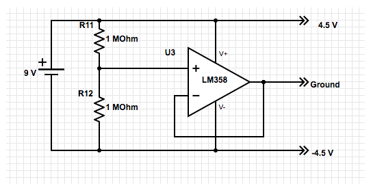
Shown above is the battery circuit we developed to set lines for 4.5 V and - 4.5 V. This feature of our project was necessary to power the amplifiers in the above circuit while also maintaining an electrically isolated system. We first used R11 and R12, two 1 MOhm resistors, in a voltage divider to evenly divide the 9 V supply from the battery into three nodes that are apart by 4.5 V as shown. We then used another LM358 operational amplifier, in a design known as a voltage follower. By shorting the output to the input of the amplifier, we create a more stable ground line and create a circuit with very high input impedance (and low output impedance).
Inclusion of the voltage follower effectively isolates our battery circuit from the other circuits we use it to power: Voltage signals present at the input of the amplifier see a very high impedance and do not interact with the amplifying circuit. Similarly, voltage signals present in the amplifying circuit see a very low output impedance and only fall across this component of the circuit system.
To play sounds during the game, we will be using direct memory access (DMA) to drive an SPI channel. DMA is a capability on the board that allows configuration of a remote processor to transfer values in memory to a destination without consuming CPU resources aside from setup. We will use DMA to transfer memory from sound tables stored in flash to a DAC (digital-to-analog converter), leading to a speaker as a final output.
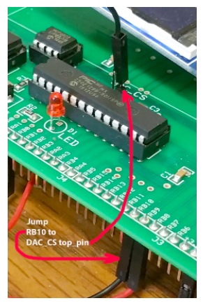
The SPI DAC that we will be using will be MCP4822. To configure the DMA in hardware, we need to use the modify the chip-select pin on the SPI channel to use framed SPI. The reason why we do this is because framed SPI mode allows the SPI controller to toggle the chip select line, implying that only one peripheral can be attached to that channel. This feature allows the DMA channel to blast data out to the DAC without the use of an ISR. The DMA channel hardware triggered by a timer event, will blast data out of flash memory of table voltages to an SPI transmit register. This greatly simplifies our logic in our code as we will discuss in the Software Description. To allow for framed SPI mode to toggle the chip-select line on the SPI channel we must jump RB10 to top pin of DAC_CS as in the figure below.
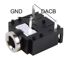
To play the sound, we must connect the audio socket to the output of the SPI DAC. The nearest pin to the socket is ground. The other two pins are shorted together and connected to DACB pin on the large board as in Figure 4.
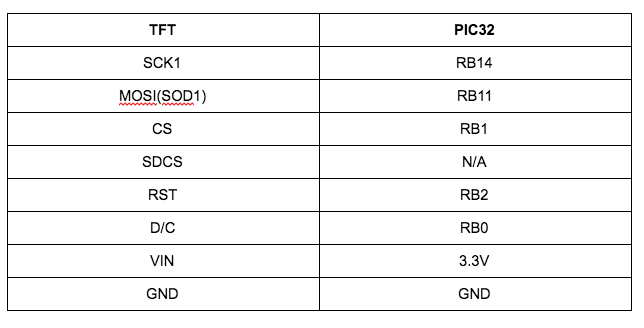
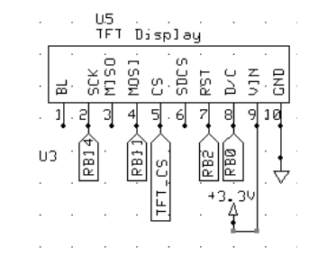
Our microcontroller board includes a TFT display, which we will use to visualize the game. The connections to the TFT display are shown below. The TFT uses an SPI channel to communicate with the PIC32.
To control the voltage offset, we use a potentiometer with the washer connected to the inverting input of our balanced subtractor stage. As in the below figure, the washer is connected to the Voffset input at pin 2 of the LM358. The circuit in the left is used to create a user-variable voltage in Figure 3. We use the user-variable voltage at the amplifier input to control the range of Voffset values used to calibrate the game.
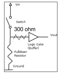
In the game, we use a manual button input to end the calibration stage and begin the game. For the circuit, we used a regular pull down circuit as displayed in Figure 4. Our pin assignment is to connect the button to Vdd through a 300 Ohm resistor going through pin RA2. The pulldown resistor will be enabled in software and turned on by the button press to enable a digital signal.
Our project design included one significant step that bridged the hardware and software, as we needed to calibrate our Voffset to an appropriate value for the ADC. We needed to make sure that the hardware output sits between 0-3.3V the voltage acceptance range of the ADC. We did this by the following:
1) Begin the program, without yet pressing the button to begin the game. In this state, the program still prints the ADC value to the screen, and the paddle will still move based on a change in the input, but obstacles have not started spawning.
2) Have the user look straight ahead. Carefully adjust the potentiometer until the ADC reading is close to 512, representing the center point. Make sure that the paddle moves properly upon looking left and right.
3) Press the button and start the game.
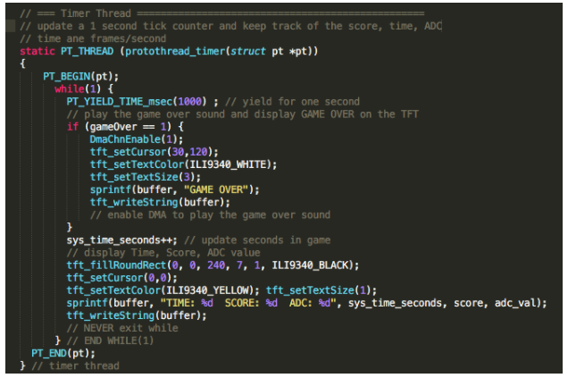
The purpose of the Timer Thread is to update a 1 second tick counter and to display the current score of the game, current time, and the value of the ADC. The Timer Thread will also determine whether the game has ended. This thread first calls PT_YIELD_TIME_msec(1000), a ProtoThreads function that waits for the argument given in milliseconds. In other words, our thread repeats continuously at 1 Hz.
On every iteration it also checks the status of the global gameOver variable, which is set in our dynamics thread. Once gameOver is set to 1, the timer thread first calls DmaChnEnable(1) - the DMA function that enables the new game over sound. It also calls several TFT functions to print a big, white “GAME OVER” message to the screen. The three functions tft_setCursor, tft_setTextColor, and tft_setTextSize set the location of the printed message, its color, and its size, respectively. Then sprintf is used to write to a buffer, and tft_writeString(buffer) prints the buffer variable to the screen given the settings above. Again, all of these functions are available in the TFT libraries "tft_master.h" and "tft_gfx.h".
We store the time that the game has been running in sys_time_seconds, which is incremented every second by this thread. Then the other function of this thread is to print the three values of time, score, and ADC to the screen. First, tft_fillRoundRect is used to clear the screen in the row where these variables are written. Then a print statement is written to the buffer and printed. The score and adc_val are global variables set by logic in other threads.
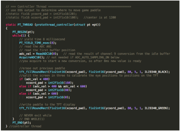
The main purpose of the controller thread is to interpret the ADC input and use it to control the paddle. Like the timer thread, it uses PT_YIELD_TIME_msec to run at a constant frequency, with 8 milliseconds between iterations.
On each iteration, it reads the ADC value by calling ReadADC10(0). Immediately after, AcquireADC10() is called to prepare the ADC to be read on the next iteration.
tft_fillRoundRect() is used to draw the paddle that the user controls. First, a black rectangle is drawn to clear the previous location of the paddle. Immediately after, the recorded adc_val is used to set the new location of the paddle. The ADC is a value between 0 and 1024, so after calibration it is centered at approximately 512 mV. We chose thresholds of 400 and 600 for the ADC value, which performed fine during testing. The threshold is used to set the value of xcoord_pad, the x coordinate of the paddle. The width of the screen in x is 240, and the paddle is 80 units wide. The coordinate used in the tft_fillRoundRect function defines the top left corner of the rectangle, so this implementation evenly divides the width of the screen into three sections based on thresholds in the ADC signal.
The dynamics thread performs the bulk of our computations, managing spawns of obstacles, updating their positions, and checking for collisions with the user-controlled paddle.
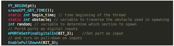
PT_BEGIN(pt) is the ProtoThreads function that begins the thread. Prior to looping, srand(PT_GET_TIME()) is used to set a random number generator seed (using the current time of the system as a random number to determine the seed). We also use mPORTASetPinsDigitalIn(BIT_3) and EnablePullDownA(BIT_3) to set the button port as an input and configure the pulldown resistor. By default, this passes a logic low to the pin until the button is pressed.
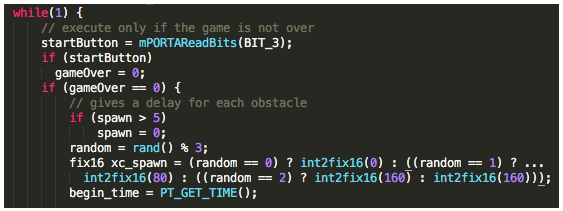
After these setup functions, the thread begins looping. First the start button is read on every iteration in order to determine the starting logic for the game, which uses our gameOver variable (initialized to -1). At the very beginning of the game when we begin the calibration stage, this thread loops with 67 milliseconds between iterations. The majority of the thread only runs if gameOver == 0, however, and does not run until we are done calibrating and the button is used to set gameOver to 0. The value of the button is read using mPORTAReadBits(BIT_3), and is set to 1 when the button is pressed. Debouncing was not a concern, as the button need only be pressed once to initiate the game; more presses don’t have an effect on the software.
The next segment of this code determines our spawn logic. Our random number generator is used to determine the starting location of each obstacle - we mod this value by 3, so that only a value of 0, 1, or 2 is recorded and can be used to set one of three locations. These three locations are the same as the paddle: 0, 80, or 160 to define the corner of the drawn round rectangle. In addition, a counter variable named “spawn” was used to only spawn an obstacle every 5th iteration of the dynamics thread.
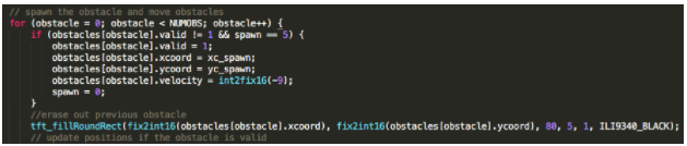
The above for loop is used to spawn a new obstacle on the screen. Our implementation uses an array of structures to define the obstacles, shown here:

Each oncoming bar is defined by an x coordinate and y coordinate for the corner (to be used for drawing), a velocity, and a valid field to define whether an obstacle is spawned or not. The above for loop uses “spawn” to wait until the 5th iteration in a row, searches for an invalid obstacle in the array, and spawns it at a location determined by the random seeding earlier (stored in “xcoord”) and sets it with a constant velocity as it approaches the user paddle. Waiting for the 5th iteration creates enough space between obstacles for the paddle to move around.
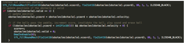
The next portion of the code (contained in the above for loop) updates the position for all valid obstacles, sending them closer to the paddle at constant velocity. Once they reach the end of the screen the thread increments the score, sets this obstacle as invalid, clears it from the screen by drawing it black, and calls DmaChnEnable(0) to play the sound to score a point.
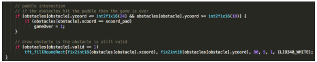
Next, the code checks if the obstacle has overlapped with the paddle, in which case the global variable gameOver is set to 1. This will register in the timer thread, resulting in a print of the game over message. Finally, the thread re-draws the valid obstacles (having cleared earlier in the loop).
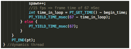
The end of the thread increments the spawn variable to separate the obstacles as they spawn. Finally, PT_YIELD_TIME_msec(67) is used to wait 67 milliseconds between threads for a framerate of 15 Hz for the obstacle dynamics. Because this thread is fairly computationally expensive, we calculate the time spent in the loop and subtract it from the 67 milliseconds after computation to ensure a 15 Hz frame rate.
The purpose of the main function is to configure the protothreads, DMA setup, ADC setup, TFT setup, initialize every ball to invalid, and start a round-robin scheduler for the threads.
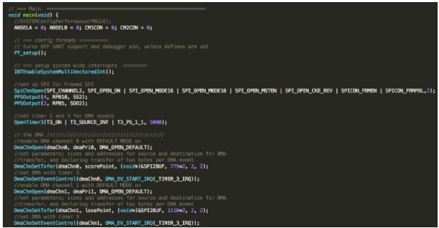
To configure the DMA, we first needed to establish a framed SPI channel using the SpiChnOpen() command, with PPSOutput() to set up the ports for data out and slave select. In the hardware aspect of framed SPI, we jumped the DAC_CS to RPB10. Here in the code, we set up the slave select port as RPB10 and we set up our data out port to be RPB5. This is needed as a bus protocol so that the PIC32 can properly establish a connection between the DMA and the DAC. The subsequent lines set up the DMA channels 0 and 1. Each channel required three commands - “DmaChnOpen”, “DmaChnSetTxfer”, and “DmaChnSetEventControl”. For each channel, these functions set the channel in default mode (so that enabling the channel runs the memory transfer once), assigns a variable as the source for the memory transfer, assigns the SPI as the destination, sets the size of memory to be transferred, declares 2 bytes per transfer, and assigns the given channel a timer event dictating the DMA frequency.
Here, we used channel 0 for our “scorePoint” sound in flash, and channel 1 for “losePoint” (our sound for the game over condition).We enabled timer 3 with a load of 5000 cycles and assigned it to both channels 1 and 2 to send these two sounds to the DAC at 8 kHz. The generation of these sound files is explained below.
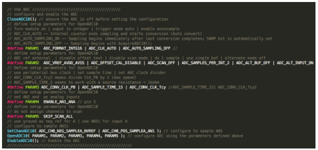
The next sequence in main() configures the ADC to read the amplified electrode signal. First, we clear the ADC and configure it to the input AN11 (on pin 24, RB13 on big board). Parameters 1-5 configure the ADC for our purposes of this game. For example, parameter 1 sets up up ADC output to be 16 bit integer format, triggers auto-conversion when the internal counter, and disables autosampling. Disabling the auto-sampling allows us to choose the sampling rate of the ADC. This means that the ADC will only begin sampling with a call to AcquireADC10(), instead of beginning immediately after the last conversion completes. This parameter allows us to more accurately control the paddle at a regular frame rate. Finally, after setting up the ADC with the correct parameters, we enable the ADC to allow sampling of the input signal.
We also initiate the protothreads used and enable the TFT display. For the TFT, we choose not to set rotation for the screen. As a result there is a discrepancy between the coordinates used for drawing and the way the game is viewed. When playing, the bottom left corner is (0,0), the y-axis is the horizontal axis, and the x-axis is the vertical axis.
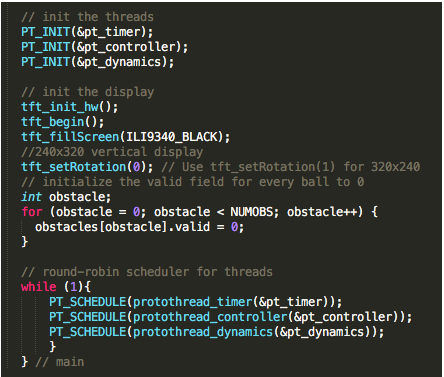
In a final step in main() prior to scheduling, we set the “valid” value for every obstacle in our structure array to 0. This ensures that we begin the game with all the obstacles despawned, and we can enable them later in real time by setting the value to 1. After this, we begin a round-robin schedule of our three threads for playing the game as described earlier.
The PIC32 does not have the storage capacity for very large sound tables in RAM. To address this, we needed a way to generate the large arrays and store them in flash instead. We adapted a MATLAB code provided from Bruce Land on the ECE 4760 course website that reads a .wav sound file and generates a corresponding C header file that stores the sampled values in an array in flash. Here is the adapted code:
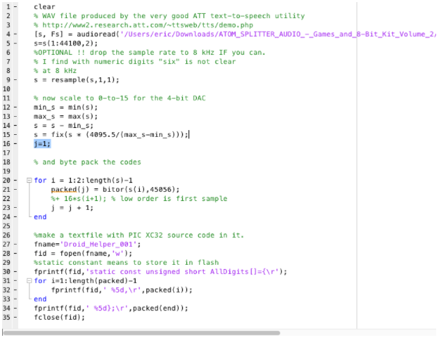
Essentially, this program reads the waveform for a .wav file using audioread into an array, and then rescales the array into a sequence of 12-bit integer values (ints between 0 and 4095), as we are using a 12-bit DAC. The “bitor” function is then used to append a sequence of 4 bits to each of the values - this sequence is 1011 or 0xb, to be used with DAC B on the PIC32. The value 45056 is equivalent to 0xb000 - the computation is 0x0XXX | 0xb000 -> 0xbXXX. After setting the proper values for the array, the program outputs a C header file that defines a “static const unsigned short” array. The “static const” part indicates permanent storage in flash, and shorts indicate that each value will occupy 2 bytes.
An additional concern was the sampling of the sound files. We used the “resample” function to downsample the sounds, reducing the amount of memory to be stored in flash. Here, the code is set to produce a file for our game over sound, and resample(s,1,1) simply reproduces the given input. A different resampling such as resample(s,1,5) can downsample a sound from 44100 Hz to 8820 Hz, which changes the size of the generated array to accommodate. These sounds must then be played back at an appropriate rate during the game - this uses timers as is explained above.
Notes: Both sounds used contain two channels - for both of them, channel 2 was the one containing the sound content, and this was the sampled array that was processed and saved in the header file. All sounds were taken from open-source online library freesound.org. The original code was modified from reading 4 bit values from the array, using one channel, byte-packing the values, and saving 1-byte chars.
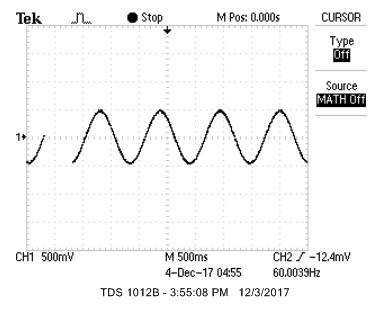
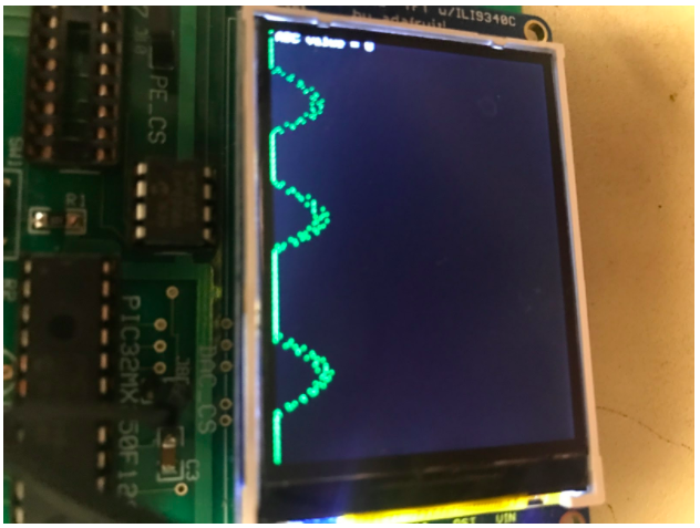
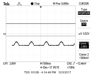
Here is an image of our oscilloscope implementation on the TFT in comparison to the signal picked up by the oscilloscope.
|
Testing our design comprised of the bulk of our time over the course of these five weeks. After designing the hardware schematic for the amplification circuits, we began with unit testing for each stage, separating them until we found that they worked independently of each other. To test the first stage, we mimicked EOG signals at the input by creating a voltage divider across a signal generator of 1 Vpp, shown below:
|
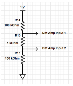
By inputting the 1Vpp signal from the signal generator, we generate two signals at the output Diff amp input 1 and Diff Amp input in the figure below,
This circuit was used to generate a 4.98 mVpp differential voltage at the inputs, which is similar to those of EOG signals. Note, however, that there is no DC offset in this testing scheme while there is a significant offset in reality when testing with the electrodes. The calculations for these differential signals is calculated below:
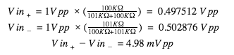
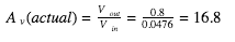
After creating this testing scheme we probed the output on the oscilloscope until we received an output voltage that was roughly 85-90 mVpp (4.98 mV * Av, where Av = 17.7). Debugging both stages of the circuit was very tedious, since everything was completed on a breadboard. The biggest problem we ran into was loose wires due to continuous transportation to and from the lab. Once we received an output from the signal (shown below), we were able to calculate the actual gain of the first stage differential amplifier and compare it to the expected. Note that the output of the first stage is fairly noisy due to a noisy power supply. This can be suppressed by placing a capacitor tied to ground from the power supply.
|
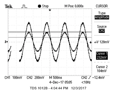
The output of the second stage subtractor circuit is shown in the figure below:
|
After completing unit-testing for the first stage, our group then moved on to unit-testing the second stage of our hardware, which was the subtractor circuit. Debugging this stage was much more complicated than the first because we dealt with larger DC voltages that would often be clipped. We found the output of the first stage to be 83.66 mVpp, which would mean that the expected output coming out of the second stage would be 4.183 Vpp. During the debugging phase, we found from the LM358 datasheet that the output clips at 1.2 V below the voltage rails (clipping at +/- 3.3 V given +/- 4.5 V rails). This is where the DC offset from the potentiometer comes in. This was our initial schematic from the potentiometer connected to the subtractor:
In this initial implementation, The offset inputting to the amplifier ranges from 0 to 4.5 volts. However, this is obviously too high of a swing for our circuit needs. After investigating why our circuit was clipping when the potentiometer was swung, we realized that we needed to add resistors to nullify much of the swing. Below is our schematic showing how we decreased the swing to reduce the voltage clipping.
Note that these resistor values will prove to fail us in the later stages of testing, since the range of this swing is too small for our ADC values when using EOG signals. This is because the input signal generator does not contain a DC offset, while electrodes/EOG have significant DC offsets.
We needed to code an oscilloscope on the TFT display to help us debug the EOG signals and isolate us from the power supplies on the walls.
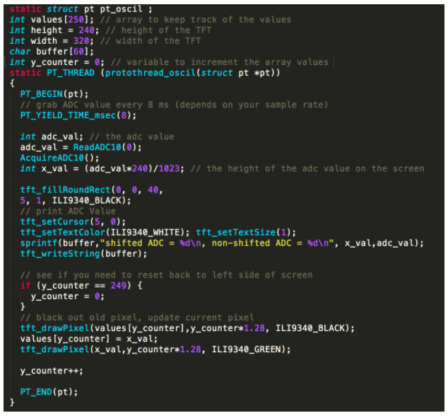
To create the oscilloscope, we first created some global variables and arrays: values, width, height, y_counter and buffer. In the thread, we yield every 8msec, to determine the sampling rate at which we sample the ADC. We choose 8msec, because we desired to achieve 250 sampling points within 2 seconds. We first grab the ADC value by calling ReadADC10(0). We then acquire the next adc values by calling AcquireADC10(). Our variable x_val is the variable that corresponds to the height of the signal on the TFT. Since the maximum height on the TFT is 240, we apply a scaling factor 240/1023 to change the ADC value to a height that will correspond to a point on the screen. We then print shifted ADC, and non-shifted ADC on the TFT display to show the corresponding ADC value and the height using basic TFT commands. We then draw the ADC value as a pixel on the screen by first blacking out the old existing pixel and then drawing a new pixel on the screen. The array values keeps track of the existing heights of the adc values that are on the screen. Since we desire to have 250 points on the screen at once, y_counter is used to increment the array values. When y_counter is equal to 249, we set the value of y_counter back to 0. When drawing the pixel on the screen, we choose to set one of the parameters to y_counter*1.28 instead of y_counter, since the total width of the TFT display is 250. We desire to show the total length of the signal through the entire width of the TFT, and since the width of the TFT display is 320, we apply a scaling factor of 1.28 to y_counter.
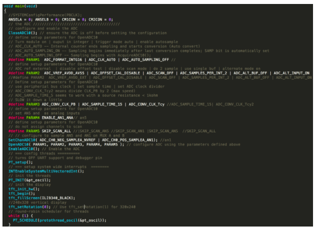
In the main code for oscilloscope.c, we generally set the ADC parameters, set up protothreads, initialize the TFT display and execute the threads. The general outline and explanation of main is similar to the main code in game.c. One important thing to notice is that the ADC sampling is set to ADC_AUTO_SAMPLING_OFF to enable us to sample whenever we choose, in this case, every 8msec.
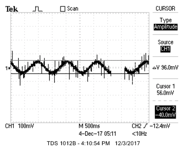
After getting the oscilloscope working on the TFT display, the next step was to display EOG signals on our PIC32 program. However, when we connected up the electrodes only a flat line displayed on the TFT. Although we initially did not know the reason for this, we noticed that as soon as we connected EOG signals to the ADC, the voltage would be clipped at 3.3V regardless of potentiometer swings. When moving input signals to those of the signal generator, however, we would see clean output signals in the form of a sine wave with small DC offset. We debugged this problem by stepping through each block in our design from input to output. From the input we measured a DC offset of roughly 20mV from the electrodes. After being amplified by the first stage differential amplifier, this offset will be amplified by 340mV. Suddenly the problem became clear! Our potentiometer swing was only giving us 40mV swing, while we needed close to 400mV to cancel out the existing DC offset. Without the cancellation, this 340mV will be amplified by the second stage circuit to become 17V DC offset. Obviously, this voltage will result in clipping from the Schottky diodes. To obtain a swing of +/- 400 mV, we used the same equations as in previous calculations for voltage division. We chose resistors of 5.1KΩ which gave us a swing shown below:
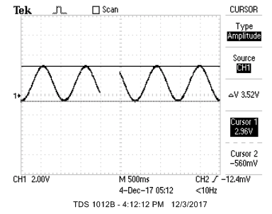
In the figures below, we display images of how an incorrect offset with an input to the system from the signal generator would look like. If the offset is too low, then it will rail to the bottom of the screen corresponding to 0V (shown below).
|
If the offset was too low then the, the signal would rail to the top of the screen, corresponding to 3.3V (shown below).
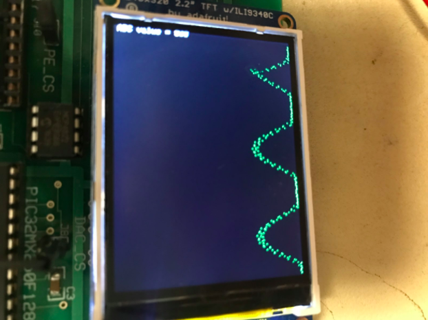
|
Once the potentiometer voltage swings were corrected, we attempted to see what the actual ADC values we were receiving when we looked left, middle, or right. This was important because this was where we would decide how to adjust the paddle position through the threshold values we picked. We set the middle view to be about an ADC value of 512. When we looked left, the ADC value was about 342 and when we looked right the ADC value was about 682. This gave us a reasonable estimate on the thresholds so that if the adc value was below 400 then the paddle would be in one position. If the ADC value was between 400 and 600 then the paddle would be in the middle position and if the ADC value was greater than 600 then the paddle would be in the last position.
The final step in our design and testing was to implement the game code with our EOG software and circuit. This was fairly straightforward, since we had already completed extensive unit testing on the circuit, oscilloscope software, and EOG calibration. Overall, the EOG controlled the paddle very smoothly from end-to-end, as long as the initial calibration was accurate. The obstacles moved very slowly and accurately because the game code would black out the old position before updating the new position, similar to lab 3. DMA produced a clean sound effects because there was no need for an ISR. We maintained 15 FPS throughout the period of the game, with no recorded lag.
We enforced safety by making all isolating every component’s power supplies from the wall. The main concern is that we are using electrodes connected to the brain. If we were not careful, we could accidentally short ourselves to the wall power supplies and generate a high enough current going through our brain that could potentially cause us to be immobile. With this in mind, we created the battery circuit to power our amplifier rails as discussed above. We created our own cable between a barrel cable and USB to supply us with 5V to power the PIC32 by using a portable battery pack. We also coded an oscilloscope source code to help us debug, to isolate us from the oscilloscope provided to us in lab. To play the sounds via DMA, we also used a portable speaker. This isolates every system from the walls.
In terms of usability for the EOG, this implementation is applicable to everyone. However, in the case that the person is visually-impaired then the game would not be applicable.
Overall, our group met or exceeded most of our expectations coming into this lab. After talking with Bruce and the TA’s, we realized that isolating EOG signals as inputs for our game would prove to be extremely challenging, especially in such a short duration of one month. We did not plan on enormous optimizations to our hardware/software, since our primary goal was to differentiate EOG signals from noise enough so that we could somewhat-smoothly play a simple game with three movement options (left, middle, right). However, at the conclusion of these 5 weeks and knowing that we are able to isolate EOG signals, we have listed several modifications that would should implement for future iterations of this project.
1. Auto-calibration at the start of each game This is, by far, the most important consideration needed for future runs of this project. The biggest flaw in our current design is that we must manually calibrate the DC offset from the potentiometer every time we want to play the game. This is because the electrodes, human EOG signals, and the circuit are extremely sensitive to any and all types of external noise. In future designs, software needs to be run that will auto-calibrate EOG signals to correct left, middle, and right inputs to the game. This can be done by having the user look to the middle for five seconds and averaging samples over that time period to obtain a correct “middle” ADC value.
2. Possible 5 inputs for game instead of 3 Currently, the user can either look far to the left, straight forward, or far to the right to trigger different input responses for the game. However, to make the game more dynamic, we can possibly use five inputs. These would be far left, slight left, middle, slight right, and far right. Based on our results, this is very feasible to implement; a typical ADC swing between left <-> middle or middle <-> right is somewhere between 150 - 200 ADC units, so fitting another input between these existing ones would not be too challenging.
3. Larger display for game Another problem with our game was that it was fairly difficult for the user to play, since the TFT display is tiny. When the user looks to the left or right to move the paddle, it suddenly becomes very difficult for him/her play the game accurately because his/her view is no longer focused on the display. To combat this, we may have to change the entire game. One brainstorm idea that we thought about with the instructors/TA’s is to create a big board (5-6 feet wide) that would contain an array of LED’s. In this implementation, looking a certain direction would light up an LED. This game is much easier for the user to play, since he/she will have full focus on that LED.
4. Solder components onto a perfboard instead of using a breadboard One of the biggest challenges in our initial hardware design and testing was debugging loose wires on the breadboard. Because our circuitry was so extensive, it was often easy for a wire to become loose and extremely hard to figure out the problem. This became a huge problem with hardware transportation as well. Once we finally got our amplifiers working, we did not move them out of the lab because it would most likely fall apart if they were transported. Testing at home would have been very useful for our lab group and would have saved us a lot of time, so in future runs of this project we would definitely solder components onto a perfboard.
The above standards presented by the ISCEV are quite rigorous, with clear intentions and accommodations for accurate medical recording. If we tried comparing our design to these specific standards, we would surely fail, as our output may not be precise enough and we certainly did not take care to properly prepare a user for clinical experiments. However, we compared fairly well to the safety requirements and design implementation, matching the standards for electrode placement, frequency cutoff, and lighting environment. Our EOG design is sufficient for use in this project due to the thresholding mechanism that determines control of the game.
In terms of software intellectual property considerations, our group implemented libraries from plib, protothreads, and adafruit TFT gfx. For writing up code use our PIC32 as an oscilloscope, we would like to thank Brian Clark for helping our group brainstorm a good way to sample and capture signals to be used in our oscilloscope. The game code for this project was written completely by our lab group with the exception of helper libraries listed earlier. In terms of hardware intellectual property considerations, we created the stage 1, 2 amplifier circuits and battery circuits with the help of Bruce Land. He gave us very helpful insight on the necessary gain to perform the necessary functions of our design. After looking at several academic papers, we realize that researchers have used EOG to perform a specific function before. However, this project is a unique application for EOG, so it could be published in a biomedical engineering magazine that details applications for EOG.
Throughout the process of this lab, our group held the IEEE ethical considerations to be of paramount importance. One of the most important parts of our lab was testing on an individual to see how his EOG response would be used as game input. However, we realized that we should never be connecting someone to a 110V AC rail due to safety concerns. To combat this, we first tested our circuit using signal generator inputs that would mimic EOG signals. The circuit was powered by a DC power supply, the output was connected to an oscilloscope, and the PIC32 was powered with a 5V barrel cable. Note that all of these devices are connected to a 110V AC rail. When the functionality of our circuit was correct, the next step was to isolate this entire configuration from the AC rail. We placed the 5V barrel cable with a connection to a portable battery, the DC power supply with a 9V rechargeable battery, the oscilloscope with an on-board oscilloscope coded onto the PIC32, and the lab speakers with a portable speaker. Another consideration that our group took in mind was to seek and accept honest criticism of technical work and to acknowledge and correct errors in our design. For example, there were many times during lab sections where we sought help due to incorrect implementation of our circuit. After consulting with Bruce, we acknowledged our flaws and sought to correct them in a new and improved design.
After looking at current research, no legal considerations have been implemented concerning EOG in our specific project implementation.
The group approves this report for inclusion on the course website.
The group approves the video for inclusion on the course youtube channel.
PIC32 MCU (Bruce Land): $5
TFT LCD Display (Bruce Land): $10
Two 9 Volt Batteries (Staples): $9
Portable USB Power Supply (7/11): $32.39
INA121 Differential Amplifier (Texas Instruments): $1.40
Two LM358 Operational Amplifiers: $1.00
Big Board (Bruce Land): $10
Microstick II (Bruce Land): $1
Two breadboards (Bruce Land): $8
Ag/AgCl Electrodes (Bruce Land): $5
Total: $82.79
Data Sheets:
INA121: http://www.ti.com/lit/ds/sbos078/sbos078.pdf
LM358: http://www.ti.com/lit/ds/symlink/lm158-n.pdf
Academic Reference:
Hasan, SM et al. Design and Implementation of a Prototype Electrooculography Based Data Acquisition System. May 2015.
All three members worked together to build the differential amplifier circuit. Evan and Alex successfully completed the differential amplifier, the balanced subtractor, and the potentiometer setting the offset voltage. Eric assembled the battery circuit. Alex led the programming endeavor, implementing the oscilloscope and contributing the most to the game code. Eric was the primary contributor to the report and wrote the HTML code. Evan was the most knowledgeable about analog circuitry and played the greatest role in ensuring successful implementation of the amplification circuit.
      /*
 * File:        TFT_test_BRL4.c
 * Author:      Bruce Land
 * Adapted from:
 *              main.c by
 * Author:      Syed Tahmid Mahbub
 * Target PIC:  PIC32MX250F128B
 */

////////////////////////////////////
// clock AND protoThreads configure!
// You MUST check this file!
#include "config.h"
// threading library
#include "pt_cornell_1_2_1.h"

////////////////////////////////////
// graphics libraries
#include "tft_master.h"
#include "tft_gfx.h"
// need for rand function
#include
#include
////////////////////////////////////
#include "Bleep_005.h" // soundtable for scoring a point
#include "Bleep_009.h" // soundtable for losing a point

/* Demo code for interfacing TFT (ILI9340 controller) to PIC32
 * The library has been modified from a similar Adafruit library
 */
// Adafruit data:
/***************************************************
  This is an example sketch for the Adafruit 2.2" SPI display.
  This library works with the Adafruit 2.2" TFT Breakout w/SD card
  ----> http://www.adafruit.com/products/1480

  Check out the links above for our tutorials and wiring diagrams
  These displays use SPI to communicate, 4 or 5 pins are required to
  interface (RST is optional)
  Adafruit invests time and resources providing this open source code,
  please support Adafruit and open-source hardware by purchasing
  products from Adafruit!

  Written by Limor Fried/Ladyada for Adafruit Industries.
  MIT license, all text above must be included in any redistribution
 ****************************************************/

// string buffer
char buffer[60];

// === thread structures ============================================
// thread control structs
static struct pt pt_timer, pt_controller, pt_dynamics;

// system 1 second interval tick
int sys_time_seconds ;
int adc_val;
int spawn = 0; // variable to indicate whether to spawn (spawn only when =3)

// === the fixed point macros ========================================
typedef signed int fix16 ;
#define multfix16(a,b) ((fix16)(((( signed long long)(a))*(( signed long long)(b)))>>16)) //multiply two fixed 16:16
#define float2fix16(a) ((fix16)((a)*65536.0)) // 2^16
#define fix2float16(a) ((float)(a)/65536.0)
#define fix2int16(a)    ((int)((a)>>16))
#define int2fix16(a)    ((fix16)((a)<<16))
#define divfix16(a,b) ((fix16)((((signed long long)(a)<<16)/(b))))
#define sqrtfix16(a) (float2fix16(sqrt(fix2float16(a))))
#define absfix16(a) abs(a)
#define dmaChn0 0 // DMA channel 0
#define dmaChn1 1 // DMA channel 1
#define dmaPri0 0 // DMA lowest priority
#define dmaPri1 1 // DMA second priority
#define NUMOBS 280 // maximum number of balls

int gameOver = -1; // variable to indicate whether the game is over
int startButton;

static fix16 yc_spawn = int2fix16(320); // y-coordinate of spawned ball
static fix16 xcoord_pad = int2fix16(100);   //center is at 1200
static fix16 ycoord_pad = int2fix16(20);

static int score = 0; // the current score of the game

typedef struct
{
  fix16 xcoord; // x coordinate of obstacle
  fix16 ycoord; // y coordinate of obstacle
  fix16 velocity; // velocity of obstacle
  char valid; // 1 is valid 0 is invalid
} obstacle_info; // struct to describe information of the obstacle

obstacle_info obstacles[NUMOBS];

// === Timer Thread =================================================
// update a 1 second tick counter and keep track of the score, time, ADC
// time ane frames/second
static PT_THREAD (protothread_timer(struct pt *pt))
{
    PT_BEGIN(pt);
      while(1) {
        PT_YIELD_TIME_msec(1000) ; // yield for one second
        // play the game over sound and display GAME OVER on the TFT
        if (gameOver == 1) {
            DmaChnEnable(1);
            tft_setCursor(30,120);
            tft_setTextColor(ILI9340_WHITE);
            tft_setTextSize(3);
            sprintf(buffer, "GAME OVER");
            tft_writeString(buffer);
            // enable DMA to play the game over sound
        }
        sys_time_seconds++; // update seconds in game
        // display Time, Score, ADC value
        tft_fillRoundRect(0, 0, 240, 7, 1, ILI9340_BLACK);
        tft_setCursor(0,0);
        tft_setTextColor(ILI9340_YELLOW); tft_setTextSize(1);
        sprintf(buffer, "TIME: %d  SCORE: %d  ADC: %d", sys_time_seconds, score, adc_val);
        tft_writeString(buffer);
        // NEVER exit while
      } // END WHILE(1)
  PT_END(pt);
} // timer thread

// === Dynamics Thread =================================================
// Detect collisions, calculate total change in velocity, and update obstacles
// Also modify the score
static PT_THREAD (protothread_dynamics(struct pt *pt))
{
    PT_BEGIN(pt);
    srand(PT_GET_TIME());
    static int begin_time; // time beginning of the thread
    static int obstacle; // variable to traverse the obstacle used in spawning
    int random; // variable to determine which section to spawn
    // PortA ports as digital inputs
    mPORTASetPinsDigitalIn(BIT_3);    //Set port as input
    // and turn on pull-down on inputs
    EnablePullDownA(BIT_3);
    while(1) {
        // execute only if the game is not over
        startButton = mPORTAReadBits(BIT_3);
        if (startButton)
          gameOver = 0;
        if (gameOver == 0) {
            // gives a delay for each obstacle
            if (spawn > 5)
                spawn = 0;
            random = rand() % 3;
            fix16 xc_spawn = (random == 0) ? int2fix16(0) : ((random == 1) ? ...
              int2fix16(80) : ((random == 2) ? int2fix16(160) : int2fix16(160)));
            begin_time = PT_GET_TIME();

            // spawn the obstacle and move obstacles
            for (obstacle = 0; obstacle < NUMOBS; obstacle++) {
                if (obstacles[obstacle].valid != 1 && spawn == 5) {
                    obstacles[obstacle].valid = 1;
                    obstacles[obstacle].xcoord = xc_spawn;
                    obstacles[obstacle].ycoord = yc_spawn;
                    obstacles[obstacle].velocity = int2fix16(-9);
                    spawn = 0;
                }
                //erase out previous obstacle
                tft_fillRoundRect(fix2int16(obstacles[obstacle].xcoord), fix2int16(obstacles[obstacle].ycoord), 80, 5, 1, ILI9340_BLACK);
                // update positions if the obstacle is valid
                if (obstacles[obstacle].valid == 1) {
                    // update position
                    obstacles[obstacle].ycoord = obstacles[obstacle].ycoord + obstacles[obstacle].velocity;

                    // if the balls pass the paddle, increment score, invalidate the ball, play sound and erase ball
                    if ((obstacles[obstacle].ycoord < int2fix16(5)) && obstacles[obstacle].velocity < 0) {
                        score++;
                        obstacles[obstacle].valid = 0;
                        DmaChnEnable(0);
                        tft_fillRoundRect(fix2int16(obstacles[obstacle].xcoord), fix2int16(obstacles[obstacle].ycoord), 80, 5, 1, ILI9340_BLACK);
                    }

                    // paddle interaction
                    // if the obstacles hit the paddle then the game is over
                    if (obstacles[obstacle].ycoord <= int2fix16(24) && obstacles[obstacle].ycoord >= int2fix16(18)) {
                        if (obstacles[obstacle].xcoord == xcoord_pad)
                            gameOver = 1;
                    }

                    // draw obstacle is the obstacle is still valid
                    if (obstacles[obstacle].valid == 1)
                        tft_fillRoundRect(fix2int16(obstacles[obstacle].xcoord), fix2int16(obstacles[obstacle].ycoord), 80, 5, 1, ILI9340_WHITE);
                }
            }
            spawn++;
            //15 fps => frame time of 67 mSec
            int time_in_loop = PT_GET_TIME() - begin_time;
            PT_YIELD_TIME_msec(67 - time_in_loop);
        } else {
            PT_YIELD_TIME_msec(67);
        }
    }
    PT_END(pt);
} //dynamics thread

// === Controller Thread =================================================
// use EOG output to determine where to move game paddle
//static fix16 ycoord_pad = int2fix16(20);
//static fix16 xcoord_pad = int2fix16(100);   //center is at 1200

static PT_THREAD (protothread_controller(struct pt *pt))
{
    PT_BEGIN(pt);
    while(1) {
        // yield time 8 millisecond
        PT_YIELD_TIME_msec(8);
        // read the ADC AN1
        // read the first buffer position
        adc_val = ReadADC10(0);   // read the result of channel 9 conversion from the idle buffer
        AcquireADC10(); // not needed if ADC_AUTO_SAMPLING_ON below
        //you acquire to start a new conversion, so after 8ms new value is ready

        //erase out previous paddle
        tft_fillRoundRect(fix2int16(xcoord_pad), fix2int16(ycoord_pad), 80, 5, 1, ILI9340_BLACK);
        //split the screen in three to calibrate the eye positions to positions on the TFT
        if (adc_val < 400)
            xcoord_pad = int2fix16(160);
        else if (adc_val > 400 && adc_val < 600)
            xcoord_pad = int2fix16(80);
        else if (adc_val > 600)
            xcoord_pad = int2fix16(0);

        //write paddle to the TFT display
        tft_fillRoundRect(fix2int16(xcoord_pad), fix2int16(ycoord_pad), 80, 5, 1, ILI9340_GREEN);

        // NEVER exit while
    }   // END WHILE(1)
    PT_END(pt);
} //controller thread

// === Main  ======================================================
void main(void) {
  //SYSTEMConfigPerformance(PBCLK);
  ANSELA = 0; ANSELB = 0; CM1CON = 0; CM2CON = 0;

  // === config threads ==========
  // turns OFF UART support and debugger pin, unless defines are set
  PT_setup();

  // === setup system wide interrupts  ========
  INTEnableSystemMultiVectoredInt();

  //set up SPI for Framed SPI
  SpiChnOpen(SPI_CHANNEL2, SPI_OPEN_ON | SPI_OPEN_MODE16 | SPI_OPEN_MODE16 | SPI_OPEN_MSTEN | SPI_OPEN_CKE_REV | SPICON_FRMEN | SPICON_FRMPOL,2);
  PPSOutput(4, RPB10, SS2);
  PPSOutput(2, RPB5, SDO2);

  //set timer 2 and 3 for DMA sounds
  OpenTimer3(T3_ON | T3_SOURCE_INT | T3_PS_1_1, 5000);

  // the DMA ////////////////////////////////////////
  //enable DMA channel 0 with DEFAULT MODE on
  DmaChnOpen(dmaChn0, dmaPri0, DMA_OPEN_DEFAULT);
  //set parameters; sizes and addresses for source and destination for DMA
  //transfer, and declaring transfer of two bytes per DMA event
  DmaChnSetTxfer(dmaChn0, scorePoint, (void*)&SPI2BUF, 779*2, 2, 2);
  //set DMA with timer 3
  DmaChnSetEventControl(dmaChn0, DMA_EV_START_IRQ(_TIMER_3_IRQ));
  //enable DMA channel 1 with DEFAULT MODE on
  DmaChnOpen(dmaChn1, dmaPri1, DMA_OPEN_DEFAULT);
  //set parameters; sizes and addresses for source and destination for DMA
  //transfer, and declaring transfer of two bytes per DMA event
  DmaChnSetTxfer(dmaChn1, losePoint, (void*)&SPI2BUF, 1110*2, 2, 2);
  //set DMA with timer 3
  DmaChnSetEventControl(dmaChn1, DMA_EV_START_IRQ(_TIMER_3_IRQ));

  // the ADC ///////////////////////////////////////
  // configure and enable the ADC
  CloseADC10(); // ensure the ADC is off before setting the configuration
  // define setup parameters for OpenADC10
  // Turn module on | ouput in integer | trigger mode auto | enable autosample
  // ADC_CLK_AUTO -- Internal counter ends sampling and starts conversion (Auto convert)
  // ADC_AUTO_SAMPLING_ON -- Sampling begins immediately after last conversion completes; SAMP bit is automatically set
  // ADC_AUTO_SAMPLING_OFF -- Sampling begins with AcquireADC10();
  #define PARAM1  ADC_FORMAT_INTG16 | ADC_CLK_AUTO | ADC_AUTO_SAMPLING_OFF //
  // define setup parameters for OpenADC10
  // ADC ref external  | disable offset test | disable scan mode | do 1 sample | use single buf | alternate mode off
  #define PARAM2  ADC_VREF_AVDD_AVSS | ADC_OFFSET_CAL_DISABLE | ADC_SCAN_OFF | ADC_SAMPLES_PER_INT_2 | ADC_ALT_BUF_OFF | ADC_ALT_INPUT_ON
  // Define setup parameters for OpenADC10
  // use peripherial bus clock | set sample time | set ADC clock divider
  // ADC_CONV_CLK_Tcy2 means divide CLK_PB by 2 (max speed)
  // ADC_SAMPLE_TIME_5 seems to work with a source resistance < 1kohm
  #define PARAM3 ADC_CONV_CLK_PB | ADC_SAMPLE_TIME_15 | ADC_CONV_CLK_Tcy //ADC_SAMPLE_TIME_15| ADC_CONV_CLK_Tcy2
  // define setup parameters for OpenADC10
  // set AN1 and  as analog inputs
  #define PARAM4  ENABLE_AN1_ANA // pin 3
  // define setup parameters for OpenADC10
  // do not assign channels to scan
  #define PARAM5  SKIP_SCAN_ALL
  // use ground as neg ref for A | use AN11 for input A
  // configure to sample AN11
  SetChanADC10( ADC_CH0_NEG_SAMPLEA_NVREF | ADC_CH0_POS_SAMPLEA_AN1 ); // configure to sample AN1
  OpenADC10( PARAM1, PARAM2, PARAM3, PARAM4, PARAM5 ); // configure ADC using the parameters defined above
  EnableADC10(); // Enable the ADC
  ///////////////////////////////////////////////////////

  // init the threads
  PT_INIT(&pt_timer);
  PT_INIT(&pt_controller);
  PT_INIT(&pt_dynamics);

  // init the display
  tft_init_hw();
  tft_begin();
  tft_fillScreen(ILI9340_BLACK);
  //240x320 vertical display
  tft_setRotation(0); // Use tft_setRotation(1) for 320x240
  // initialize the valid field for every ball to 0
  int obstacle;
  for (obstacle = 0; obstacle < NUMOBS; obstacle++) {
    obstacles[obstacle].valid = 0;
  }

  // round-robin scheduler for threads
  while (1){
      PT_SCHEDULE(protothread_timer(&pt_timer));
      PT_SCHEDULE(protothread_controller(&pt_controller));
      PT_SCHEDULE(protothread_dynamics(&pt_dynamics));
      }
  } // main

// === end  ======================================================
      ////////////////////////////////////
// clock AND protoThreads configure!
// You MUST check this file!
#include "config.h"
// threading library
#include "pt_cornell_1_2_1.h"
////////////////////////////////////
// graphics libraries
// SPI channel 1 connections to TFT
#include "tft_master.h"
#include "tft_gfx.h"

// === thread structures ============================================
// thread control structs
// note that UART input and output are threads
static struct pt pt_oscil ;
int value; // data received from analog port
int values[250];
int height = 240;
int width = 320;
char buffer[60];

int y_counter = 0;

float TFT_scale = 240/1023;

static PT_THREAD (protothread_oscil(struct pt *pt))
{
  PT_BEGIN(pt);
  // grab ADC value every 6? ms (depends on your sample rate)
  PT_YIELD_TIME_msec(8);

  int adc_val;
  adc_val = ReadADC10(0);
  AcquireADC10();
  //int x_val = adc_val;//(adc_val * 240) >> 8;
  //int x_val = (adc_val << 8) >> 9;  // >> 8
  //int x_val = adc_val << 2;
  //int x_val = ((adc_val << 8) - 16) >> 10;
  int x_val = (adc_val*240)/1023;

  tft_fillRoundRect(0, 0, 40,
  5, 1, ILI9340_BLACK);
  // print ADC Value
  //tft_fillScreen(ILI9340_BLACK);
  tft_setCursor(5, 0);
  tft_setTextColor(ILI9340_WHITE); tft_setTextSize(1);
  sprintf(buffer,"shifted ADC = %d\n, non-shifted ADC = %d\n", x_val,adc_val);
  tft_writeString(buffer);

  // see if you need to reset back to left side of screen
  if (y_counter == 249) {
    y_counter = 0;
  }
  // black out old pixel, update current pixel
  tft_drawPixel(values[y_counter],y_counter*1.28, ILI9340_BLACK);
  values[y_counter] = x_val;
  tft_drawPixel(x_val,y_counter*1.28, ILI9340_GREEN);

  y_counter++;

  PT_END(pt);
}

void main(void)
{
  //SYSTEMConfigPerformance(PBCLK);
    ANSELA = 0; ANSELB = 0; CM1CON = 0; CM2CON = 0;


    // the ADC ///////////////////////////////////////
    // configure and enable the ADC
    CloseADC10(); // ensure the ADC is off before setting the configuration

  // define setup parameters for OpenADC10
  // Turn module on | ouput in integer | trigger mode auto | enable autosample
  // ADC_CLK_AUTO -- Internal counter ends sampling and starts conversion (Auto convert)
  // ADC_AUTO_SAMPLING_ON -- Sampling begins immediately after last conversion completes; SAMP bit is automatically set
  // ADC_AUTO_SAMPLING_OFF -- Sampling begins with AcquireADC10();
  #define PARAM1  ADC_FORMAT_INTG16 | ADC_CLK_AUTO | ADC_AUTO_SAMPLING_OFF //

  // define setup parameters for OpenADC10
  // ADC ref external  | disable offset test | disable scan mode | do 2 sample | use single buf | alternate mode on
  #define PARAM2  ADC_VREF_AVDD_AVSS | ADC_OFFSET_CAL_DISABLE | ADC_SCAN_OFF | ADC_SAMPLES_PER_INT_2 | ADC_ALT_BUF_OFF | ADC_ALT_INPUT_ON
  //#define PARAM2  ADC_VREF_AVDD_EXT | ADC_OFFSET_CAL_DISABLE | ADC_SCAN_OFF | ADC_SAMPLES_PER_INT_2 | ADC_ALT_BUF_OFF | ADC_ALT_INPUT_ON
  //
  // Define setup parameters for OpenADC10
  // use peripherial bus clock | set sample time | set ADC clock divider
  // ADC_CONV_CLK_Tcy2 means divide CLK_PB by 2 (max speed)
  // ADC_SAMPLE_TIME_5 seems to work with a source resistance < 1kohm
  // SLOW it down a little
  #define PARAM3 ADC_CONV_CLK_PB | ADC_SAMPLE_TIME_15 | ADC_CONV_CLK_Tcy //ADC_SAMPLE_TIME_15| ADC_CONV_CLK_Tcy2

  // define setup parameters for OpenADC10
  // set AN5 and  as analog inputs
  #define PARAM4 ENABLE_AN1_ANA// an5

  // define setup parameters for OpenADC10
  // do not assign channels to scan
  #define PARAM5 SKIP_SCAN_ALL //|SKIP_SCAN_AN5 //SKIP_SCAN_AN1 |SKIP_SCAN_AN5  //SKIP_SCAN_ALL

  // // configure to sample AN5 and AN1 on MUX A and B
  SetChanADC10( ADC_CH0_NEG_SAMPLEA_NVREF | ADC_CH0_POS_SAMPLEA_AN1); //an5

  OpenADC10( PARAM1, PARAM2, PARAM3, PARAM4, PARAM5 ); // configure ADC using the parameters defined above

  EnableADC10(); // Enable the ADC
  // === config threads ==========
    // turns OFF UART support and debugger pin
    PT_setup();

    // === setup system wide interrupts  ========
    INTEnableSystemMultiVectoredInt();

    // init the threads
    PT_INIT(&pt_oscil);
    // init the display
    tft_init_hw();
    tft_begin();
    tft_fillScreen(ILI9340_BLACK);
    //240x320 vertical display
    tft_setRotation(0); // Use tft_setRotation(1) for 320x240
  // round-robin scheduler for threads
  while (1) {
      PT_SCHEDULE(protothread_oscil(&pt_oscil));
    }

}