Introduction
“A robot that allows you to focus on your life, not on cooking your steak.”
Overview and Motivations
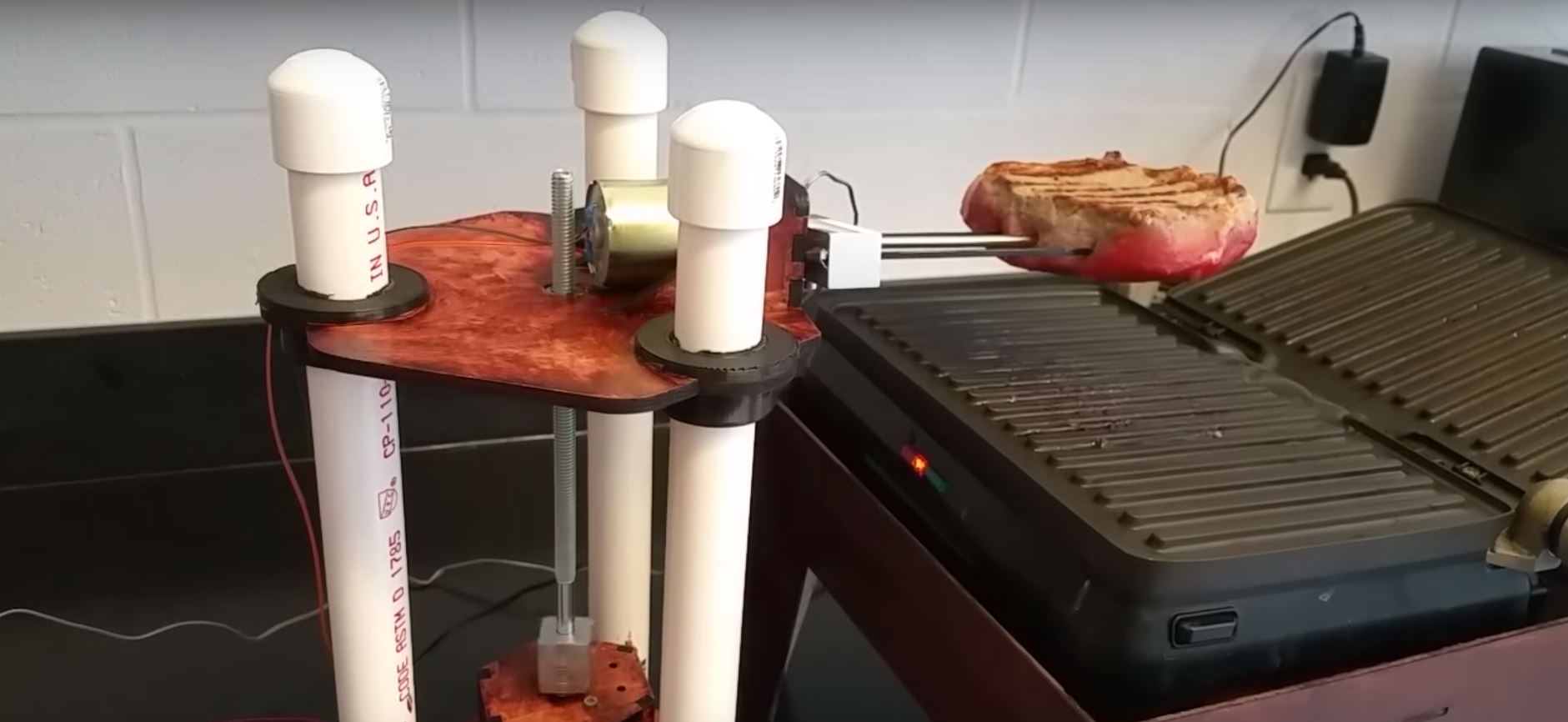
We created a steak-cooking robot. All you do is put the steak on the robot’s food-safe skewers and food probe and it does the rest. We decided to create this robot to cook better steaks using precise temperature measurements throughout the entire cooking process and, most importantly, not have to babysit the grill to achieve this.
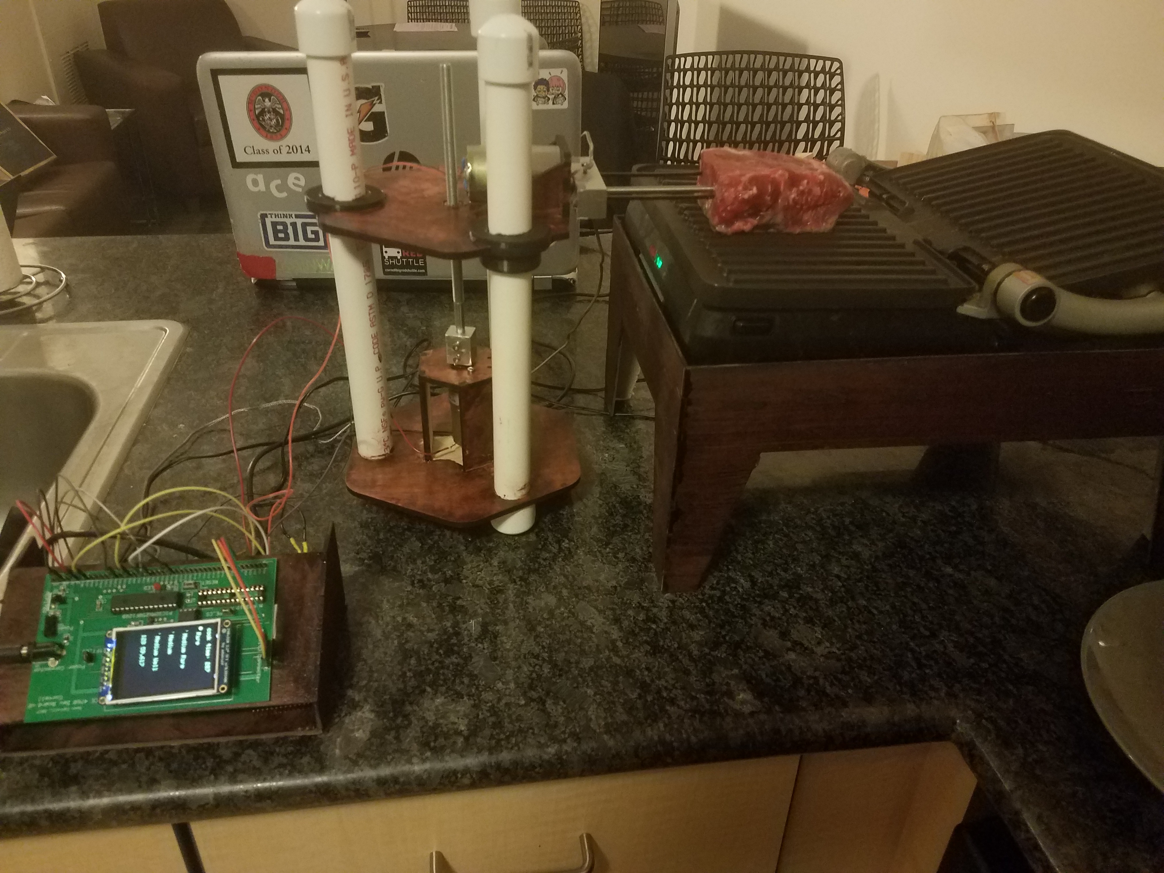
Figure 1: System Overview
High Level Design
Rational
BeefBot is a robot that cooks a steak for you using temperature sensing with no supervision after being put on the grill. Traditionally, when preparing a steak, it is often hard to get the right doneness without cutting into it to check. There exist other methods, such as using a food thermometer and comparing the feeling of the steak to your palm. These, however, require either looking up the proper temperature for desired doneness or worse, guesswork. We thought it would be very useful to create a device that would cook a steak for you using sensors rather than vague guesses. To accomplish this, we imagined a robot that would integrate with an existing kitchen appliance (stove top, pan, grill, etc.). Initial concept sketches are shown in Figures 2 and 3. With such a robot, all one would need to do to cook a perfect steak every time is put it on the robot arm and let it do the rest.
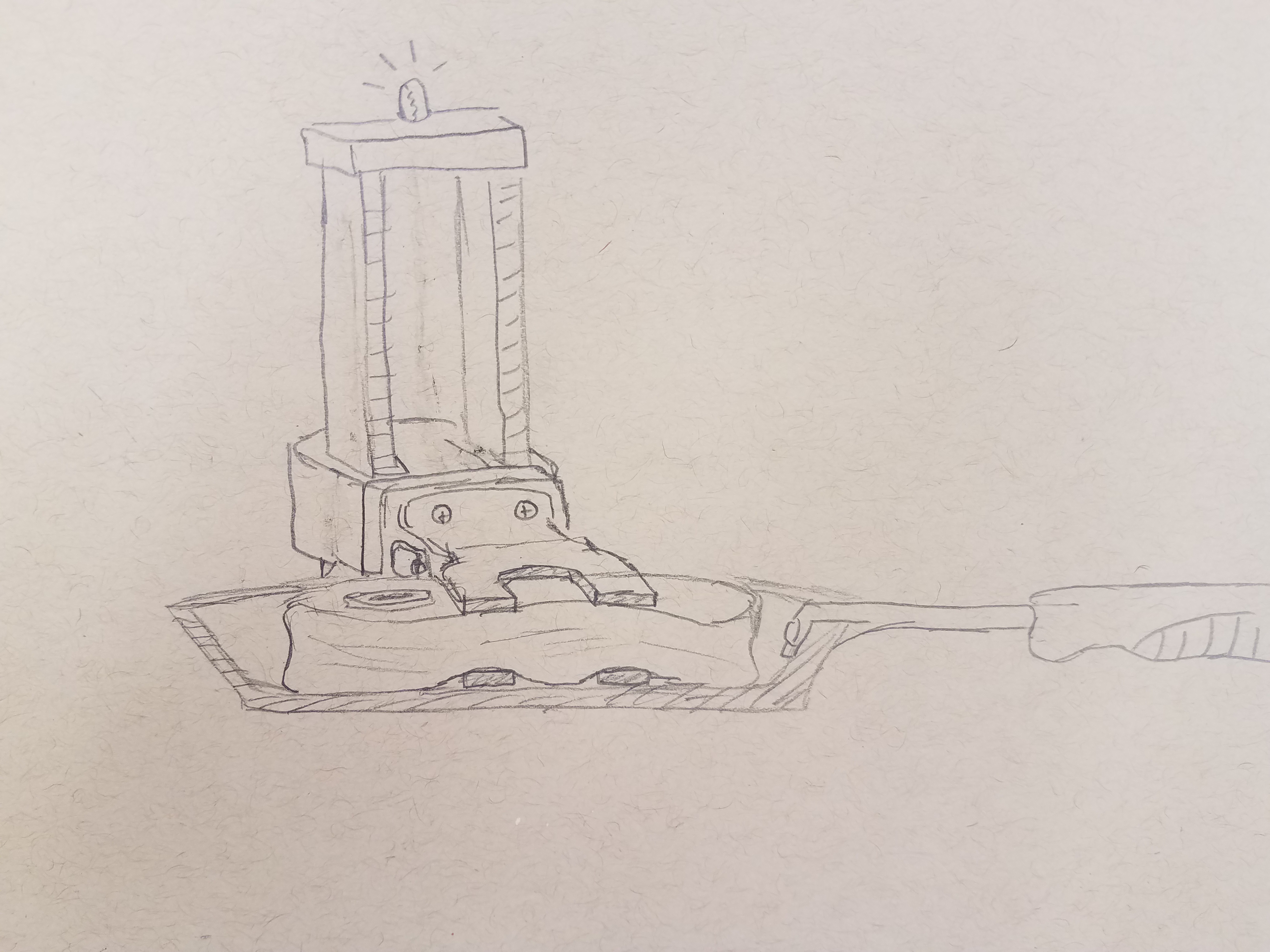
Figure 2: Concept Sketch
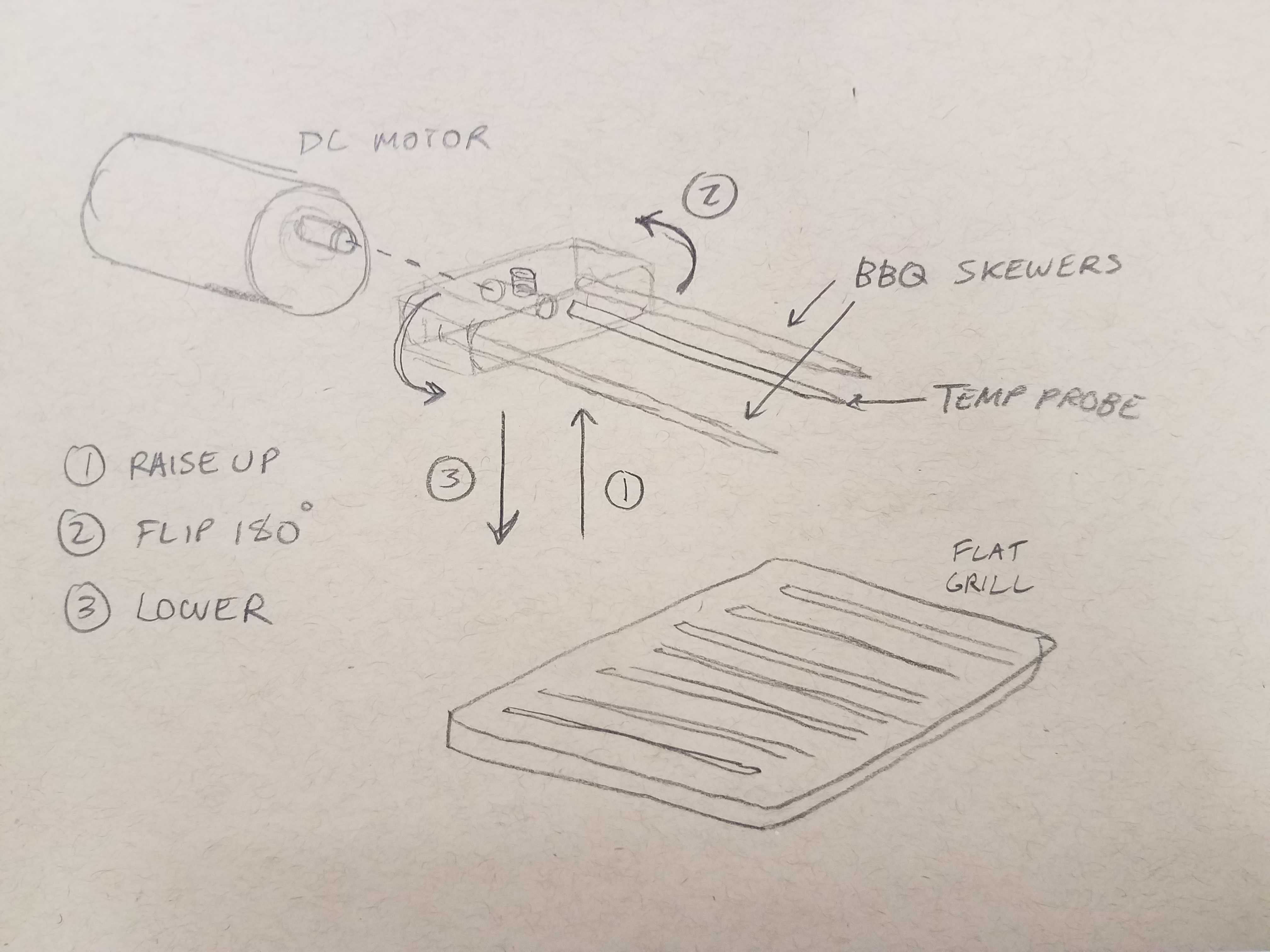
Figure 3: Motion Concept Sketch
Hardware/ Software Tradeoffs
One tradeoff was the creation of a low pass filter for our robot. We needed a filter out the excess noise coming from the foreman grill which was giving off about 60Hz from the wall socket. We came up with two solutions, one being taking a large number of samples over 1 second and averaging the results, and the other creating a low pass filter using a regulator and capacitors in series. The latter proved to be more beneficial simply because it improved the accuracy of our temperature readings and would continuously filter out all noise without a problem, whereas, using software could have decreased the accuracy of our data due to extraneous data coming through the thermometer during averaging.
Logical Structure
The main logic of our robot is to have a steak loaded onto the skewers and thermometer and be lowered onto a grill. The steak is flipped at a predetermined temperature,100 F for medium-rare, and raised from the grill to rest at a predetermined temperature, 130 F for medium-rare, as shown in the block diagram in Figure 4. Both values could depend on the meat being used and the desired doneness.
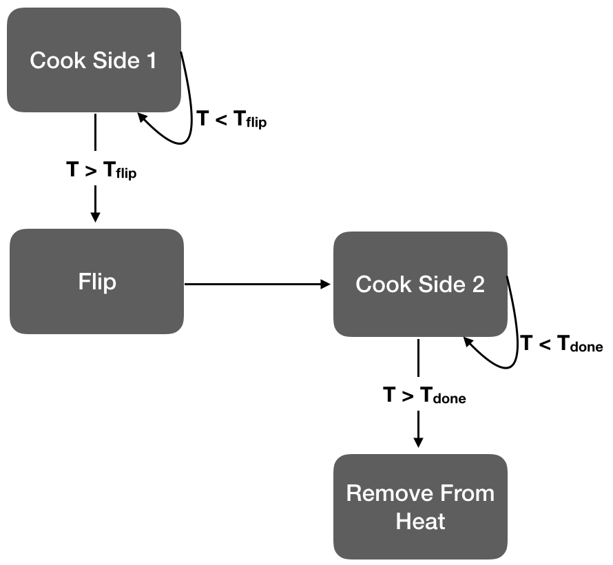
Figure 4: Program Block Diagram
Standards
Our concern when it came to standards was the food safety of our product, given that it handles raw and cooked meat (standards NSF/ANSI 2). We determined that we needed to use existing food safe parts for anything that would touch the meat, and needed to make those parts accessible to be easily washed between cooks.
Intellectual Property
The only automatic meat cooker we could find was from a company, Cinder , who sells an automatic grill. We could not find a product or patent for a design such as ours that uses two degrees of freedom to raise and flip a steak, or an automatic cooker than interfaces with an existing grill. We believe there may be some potential to patent and plan to investigate this in the near future.
Program Design
The programming for BeefBot was mainly split up into 5 categories:
- ADC for internal temperature readings and manual motor movement
- Motor control
- Feedback Loop
- The User Interface
- Cook Time
ADC
Before using the ADC, it first had to be set up properly in the main section of the code. We separated the setup into 5 separate parameters.
- Parameter 1
- ADC_FORMAT_INTG16: Allows for the ADC to output in 16 bit integer
- ADC_CLK_AUTO: Internal counter ends sampling and starts conversion (Auto convert)
- ADC_AUTO_SAMPLING_ON: Sampling begins immediately after last conversion completes; SAMP bit is automatically set
- Parameter 2
- ADC_VREF_AVDD_AVSS: Sets the reference voltages for the ADC with Vref+ at Vdd and Vref- at Vss
- ADC_OFFSET_CAL_DISABLE: disables the Offset calibrations which measures offset errors and subtracts it from the conversions
- ADC_SCAN_OFF: This setting scans through a selected vector of inputs. We disable it because we only need to scan for the potentiometer
- ADC_SAMPLES_PER_INT_2: This parameter sets up the ADC to perform two sample every time an interrupt is fired
- ADC_ALT_BUF_OFF: Alternating buffer fills
- ADC_ALT_INPUT_ON: This is used by the ADC module to alternate between the two input multiplexers
- Parameter 3
- ADC_CONV_CLK_PB: This is the peripheral bus clock used to trigger conversions
- ADC_SAMPLE_TIME_15: sets the sample time using the adc clock
- ADC_CONV_CLK_Tcy: means divide CLK_PB by 2 (max speed)
- Parameter 4
- ENABLE_AN1_ANA: Sets AN1 as an analog input
- ENABLE_AN11_ANA: Sets AN11 as an analog input
- Parameter 5
- SKIP_SCAN_ALL: This configures the ADC to not scan any channels

Figure 5: ADC Mux Code Snippet
As for the two functions of the ADC, we set up a thread for its use. Our first use was for the temperature readings of the thermistor. To convert our ADC readings into actual temperature readings we first had to plot different points on a graph between ADC values and actual temperature and then use equation of the graph within our code. So to take these plot points, we heated water, then placed our thermistor and an actual thermometer in the water. We then plotted several points as it cooled and we even chilled it with ice to get some lower end values. After that, we plotted the points and found the best possible fit to the graph, which turned out to be a cubic equation. Next, we passed this equation into our code with the adc reading being the variable and printed the result of the equation as the temperature. Lastly, we then tested our code alongside real temperature measurements and found that we were reading fairly accurately.
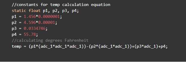
Figure 6: ADC Temperature Equation Code Snippet
Our second use for the ADC was manually controlling the motors to setup for cooking using a sliding potentiometer. This proved to be a fairly easy in implementation. We decided to use the high and low extreme ADC values, 0 and 1024, for moving BeefBot up or down, accordingly. This corresponds to one side or the other side of the slider. To do this we simply compared the read ADC value of the potentiometer, saw whether it was lower than 20 or higher than 1010, and moved it accordingly.
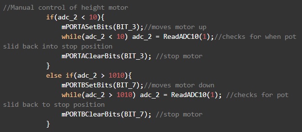
Figure 7: ADC Motor Control Code Snippet
Motor Control
The programming behind motor control primarily focused on utilising the H-Bridge for the up and down motor and setting up a PWM to assist in the control of the flipping motor. The coding for the H-Bridge was very simple. The table below basically describes how it works.
| EN | 1A | 2A | Function |
|---|---|---|---|
| H | L | H | Turn Right |
| H | H | L | Turn Left |
Table 1: Bidirectional DC Motor Control
Enable simply enables the bridge to work and we leave that on high. 1A and 2A are both input that we connected to two different pins, RB7 and RB3. All we had to do to move the motor up or down was to toggle the corresponding bit of the pin high or low. So whether in our feedback loop or our manual controller, we would take whatever trigger and just set the bit to make it high and clear it to make it low and we used delays for proper durations.
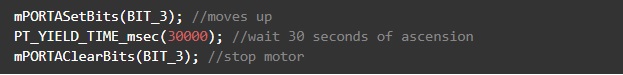
Fig 8: Raising Protocol Code Snippet
As for the PWM, we set it up using an output compare. We connected the output compare to timer2 and then also included a generated period of 40,000, which allows for a sample rate of 1kHz. We then set the output compare to a PWM in the ISR and input a variable we called duty. The variable was basically the duty cycle and we would basically change the value of this variable when the flipping is needed. We would cycle the duty between 0 and 8000, with 0 representing the motor standing still and 8000 being a comfortable flipping rate.
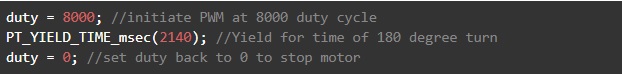
Figure 9: Flippig Protocol Code Snippet
Feedback
After having figured out the motor control and temperature sensing, coding our feedback loop was fairly simple. We created a thread to run the feedback. We first defined two temperature thresholds, one for the flip and one for the end internal temperature per sources. This was conducted for each level of cooking of a steak. The feedback loop would utilize these thresholds by constantly checking them against the the actual temperature of the steak. If the flipping threshold is crossed, the thread enables the correct pin and moves the motor up for a 30 seconds using a delay. We did some testing to decide the different delay values. We chose 30 seconds because it gave the steak enough room to flip above the grill. Next, it would change the duty to 8000 for 2120 msec and then back to 0. This proved to be the perfect amount of time for a 180 degree flip. Lastly, it would then descend for another 30 seconds to press the steak back onto the grill. After this, it would now wait for the temperature to cross the second threshold which marks a fully cooked steak. Once it reached this threshold, it moved the steak up off the grill by having the skewers ascend 30 seconds again. With that the steak is done and ready to removed for consumption by the user.

Figure 10: Feedback Loop Code Snippet
The User Interface
The user interface proved to be a very important section of the code as it set the parameters for cooking. We set up two threads for the interface, a button thread and gui thread. The button thread set up a menu selecting button. We would wire the button up to a pin and then set that pin as a digital input. We then read from the input. If the input was high, a variable called MenuSel, for menu selector, would cycle from 0-3. Each number corresponding to one of the four settings. In this same thread, we also defined the threshold values that would go along with each possible selection. We did this by checking what MenuSel was equal to and then changing the threshold accordingly. As for the gui thread, it basically controlled what exactly was drawn to the tft. It would draw each of the selections on the screen, as well as a circle to represent what was selected at the time. The circle’s position depended on the variable menuSel and would change along with the changing of the variable through button pushing.
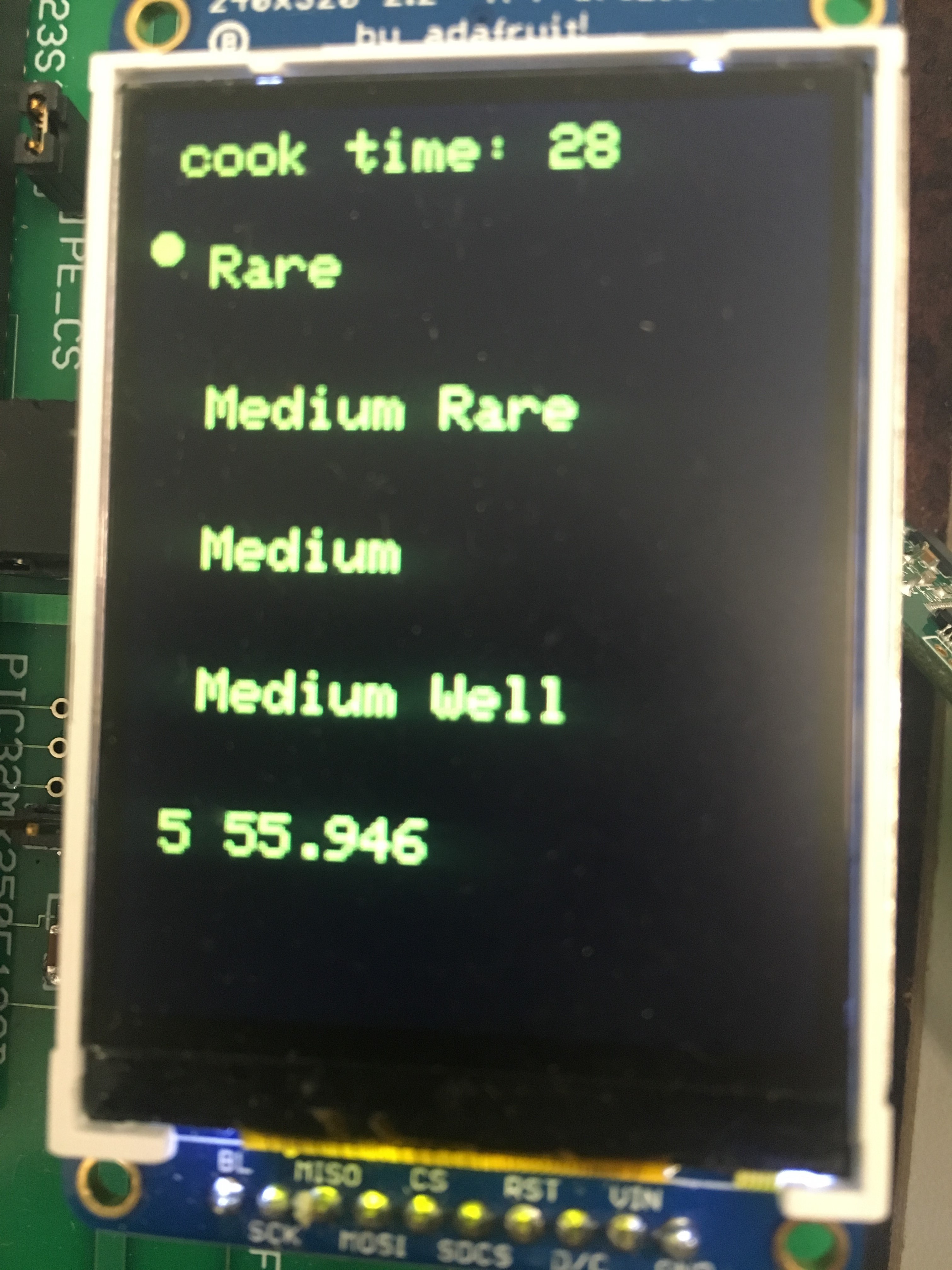
Figure 11: User Display
The Timer
The implementation of the timer is very simple. All it does is takes a variable called sys_time_seconds and yields for exactly one second before incrementing the variable. It then prints “cook time” and prints the variable next to it every second.
Hardware Design
Mechanical Design Overview
To flip a steak we identified three key motions that had to be completed. The steak had to be raised, flipped 180 degrees and then lowered back onto the grill. With this in mind we divided this process into two actuated states, raising/lowerin and flipping each with their own actuator. We decided that for the system to be autonomous the placing of the steak onto the mehanism did not have to be actuated. Our initial designs made use of clamps to constrain the steak, however since we were skewering with a probe already we opted to use skewers instead of clamps. We designed a small aluminum housing that would hold the skewers and probe and ensure rotational symmetry when the steak was flipped. To raise and lower the steak we would need a component that was being actuated and guide rails to properly constrain the platoform holding the flipping motor as it was moved. Originally we designed a rack and pinon mechanism, initial sketches can be seen in Figure 12, but later opted for a lead screw and captive nut system. We designed a platform to hold the motor with 3D printed bushings lined with fabric to prevent binding as the platform moved as well as to absorb tolerances. The CAD model used to manufacture the prototype can be seen in Figure 13. The coupler for the lead screw to motor connection was originally 3D printed but after failure during testing we opted to machine it. The final product can be seen in Figure 14.
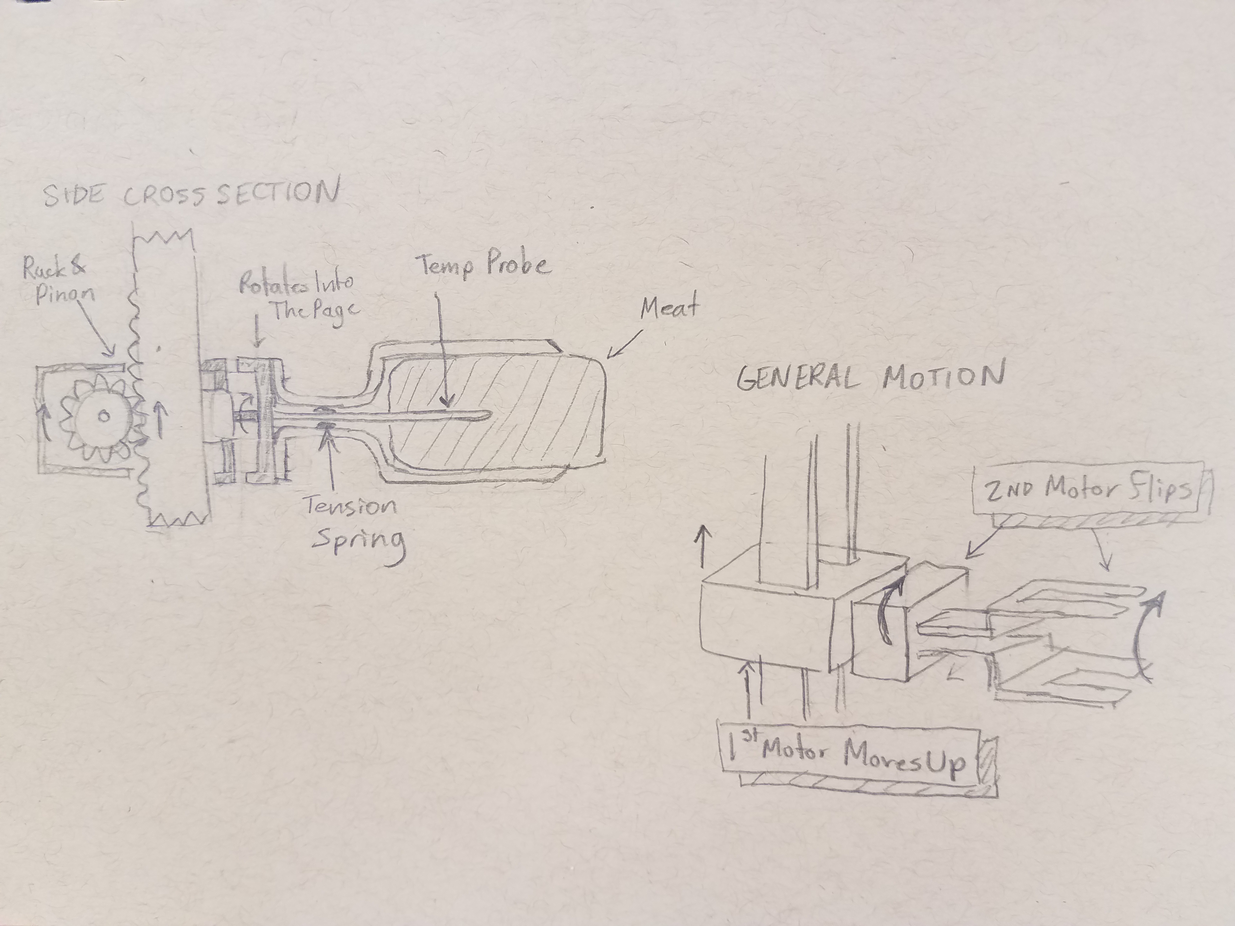
Figure 12: Linear Motion Concept Sketch
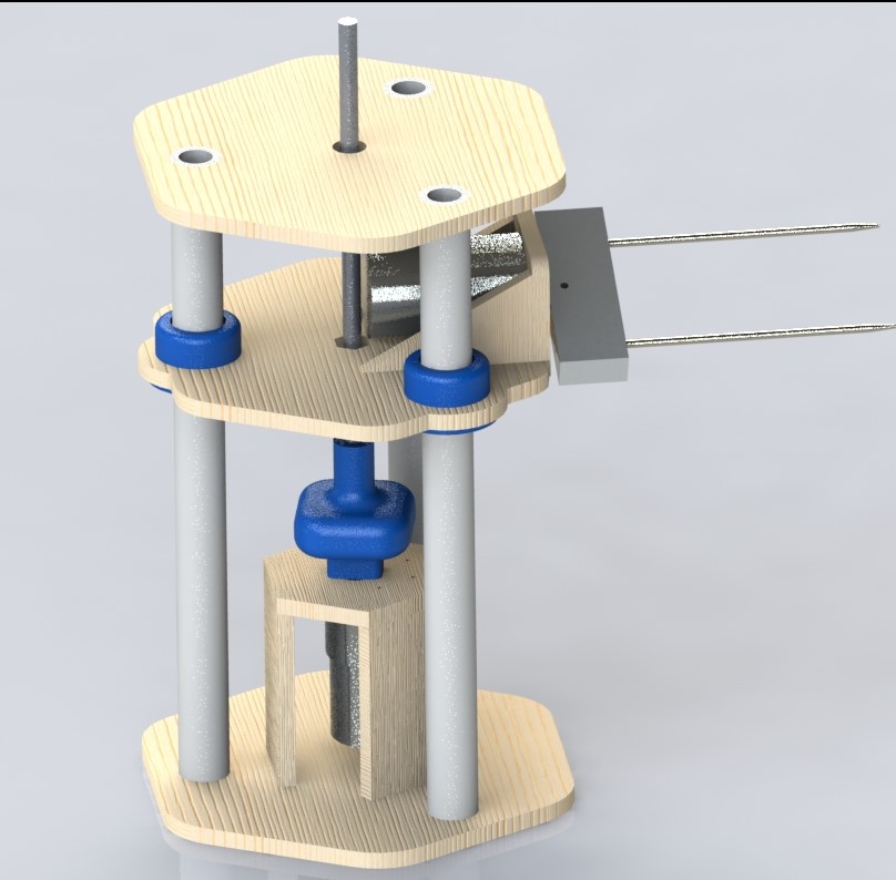
Figure 13: Mechanical System CAD Render
Figure 14: Mechanical System Final Product
Hardware Overview
Beefbot features two DC motors, shown below in Figure 15, (DC Motor Gearmotor 50 RPM 5W 12VDC) for raising the platform and flipping the steak holding components 180 degrees. The motors, as detailed below, are each controlled using PWM input through an L293D H-bridge, also shown in Figure 15. The pinout and block diagram for this H-Bridge can be seen in Figures 16 and 17.
Fig 15: DC Motor and H-Bridge
Fig 16: H-Bridge Pinout
Fig 17: H-Bridge General Schematic
Beefbot uses a thermistor in the form of a temperature food probe, which increases in resistance as temperature increases. This needed to be tuned to our ADC values, as is detailed in the results section Figure 21. The thermistor is read using a 2.5mm audio jack, shown in Figure 18, and read to the Big Board as an ADC value. The enclosure used to house the circuitry and mount the Big Board is shown in Figures 19 and 20.
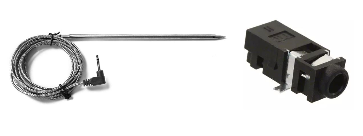
Fig 18: Thermosistor and 2.5mm Jack
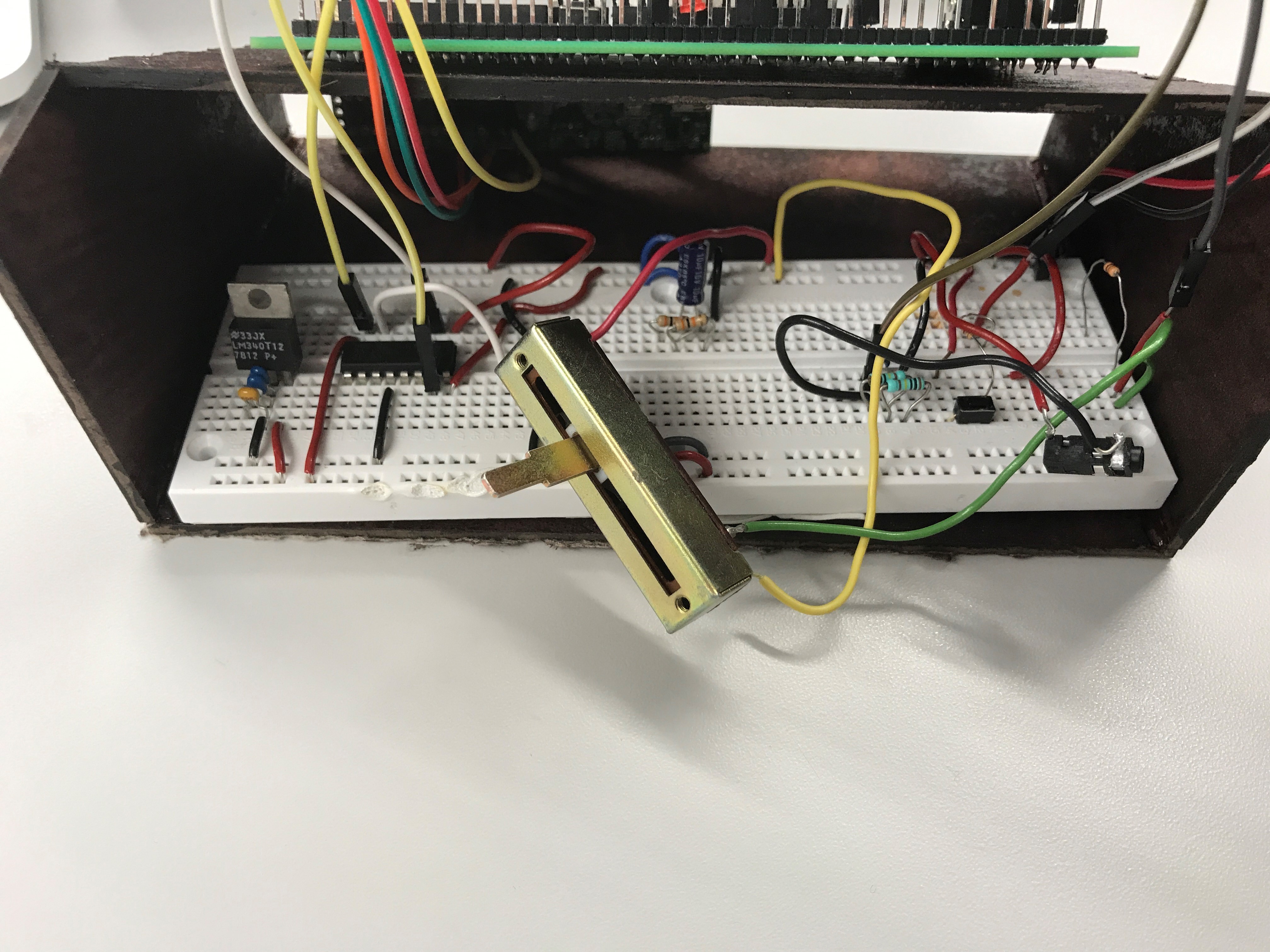
Fig 19: Physical Circuit
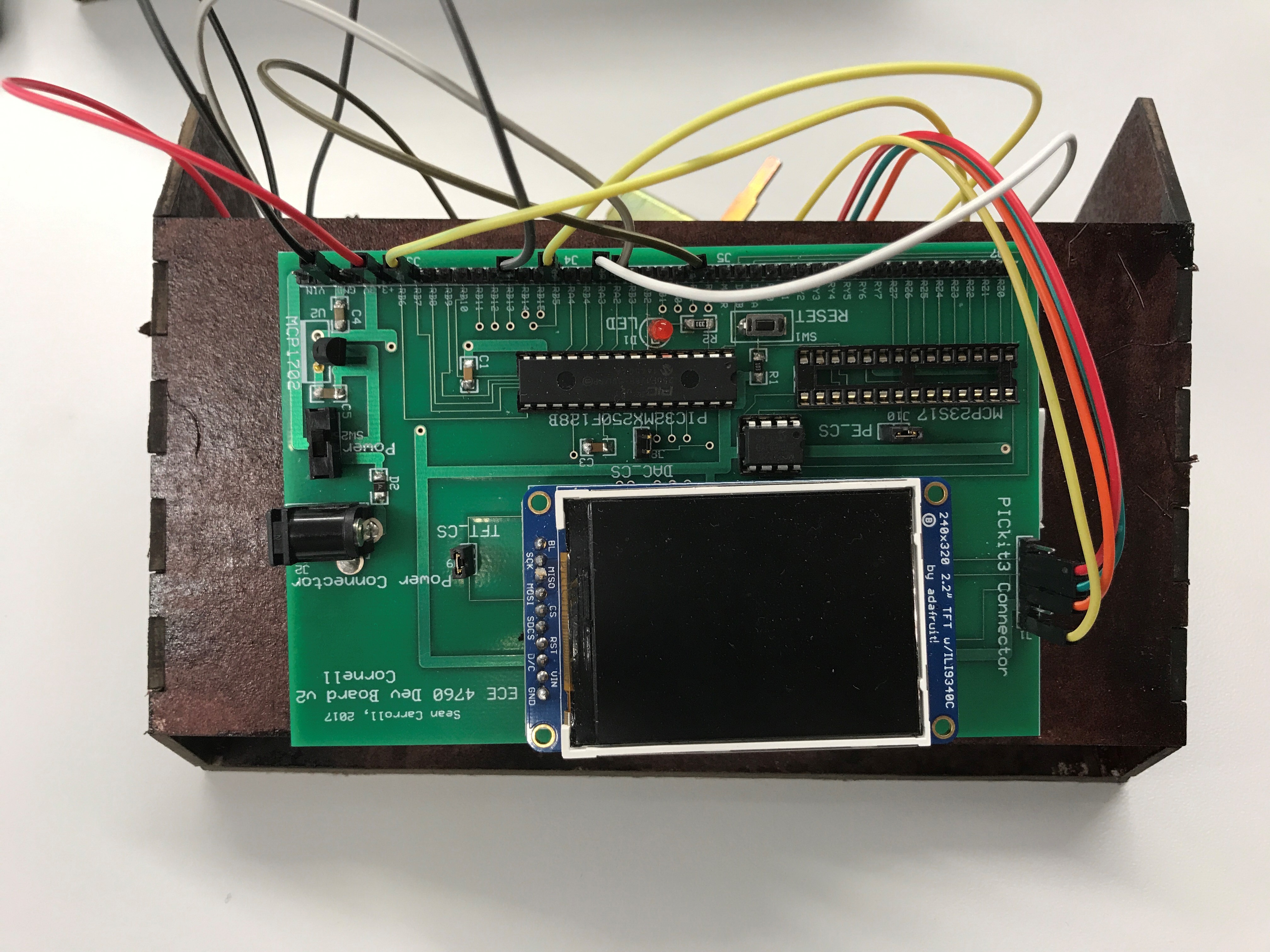
Fig 20: Display Enclosure
Debugging
The biggest issue we ran into was very noisy temperature data. When the steak was off the grill, the temperature was consistent, to about 2 degrees; however, as soon as the steak went down on the grill the temperature readings jumped around to as much as 20 degrees above or below the value read off the grill. We determined (with Professor Bruce Land’s help) that the grill, given its power input, was creating this noise. A simple resistor-capacitor low-pass filter solved this issue and reduced the noise. The result was a temperature reading that was the same whether the steak was on or off the grill.
Another, smaller issue we encountered was an inconsistent flip. To get the flip to be 180 degrees with no sensors, we needed to fine-tune the amount of time to run the motor for. After doing this, we needed to prevent the thermometer wire from getting in the way of the bolts holding the motor. With careful placement before each test, we can achieve a perfect flip every time.
Results/ Demo
To calibrate the thermometer -- which was read as an ADC voltage that changes as the thermistor increases in resistance with temperature -- we recorded ADC data points at known temperatures using a separate thermometer. From the calibration data, shown in Figure 21, we were above to fit temperature, T, as a cubic function of ADC, x.

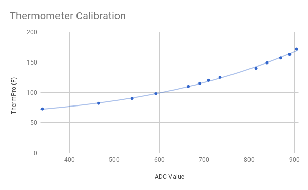
Fig 21: Thermosistor Calibration Curve
BeefBot takes about 15 minutes to cook a 1 inch thick steak, with zero human input after initially lowering it onto the grill. Figure 22 shows a typical cook. The heat takes several minutes to reach the thermometer, and reaches 80 F after about 6 minutes. At about 10 minutes, the steak reaches 100 F, which we determined experimentally to be the ideal flipping temperature. The flip is a perfect 180 degrees when the thermometer’s wire does not get in the way. If set up incorrectly, however, it could result in a less than 180 degree flip and require manual adjustment. This would need to be fixed in a future version.
From there, the temperature accelerates considerably, and at about 16 minutes, the steak reaches 130 F, the temperature at which we take it off the grill for a medium rare cook. Figure 23 shows the result of our demo, a perfectly medium rare steak. Temperature is accurate to 2 degrees. This is the normal range of noise after filtering.
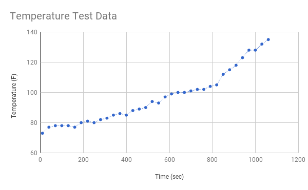
Fig 22: Temperature Test Data
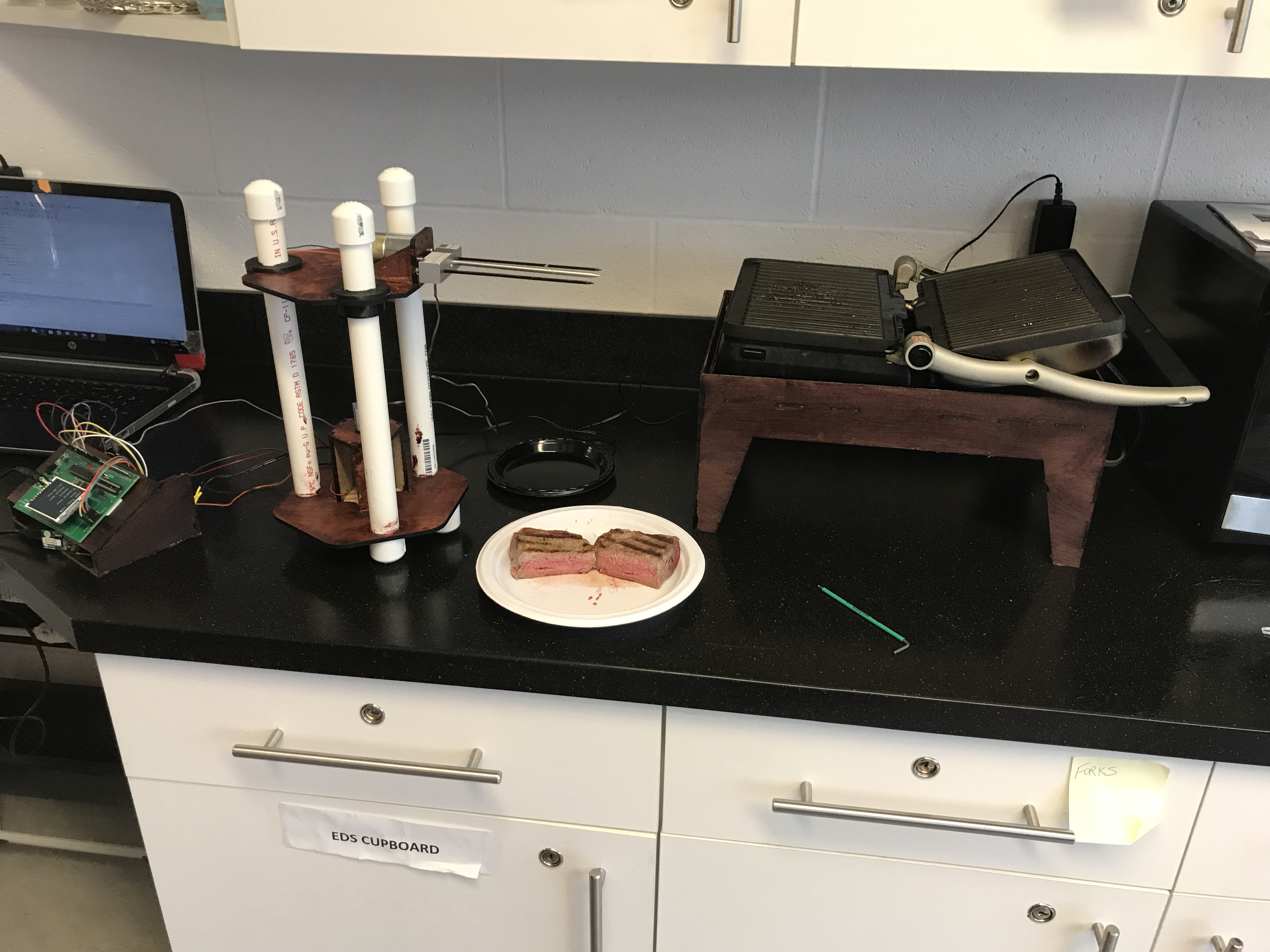
Fig 23: Final Demo Results
Safety was a concern both in handling raw and cooked food, and in interfacing our electronics with heat and food. We made the robot food safe by using only purchased, food safe parts for the parts touching the meat: barbecue skewers and a food temperature probe. For having our system close to a heat source, we ensured in our design that only the barbeque skewers and food probe would actually come near the grill. Everything else, including the flipping coupler attaching those parts to the flipper’s DC motor, did not get substantially hotter than room temperature. To keep our electronics away from meat juices, we created a separate electronics platform to keep over a foot away from the cooking setup, shown in Figures 19 and 20 .
Our robot is self-contained and does not communicate externally, so it should be unaffected by interferences, and should not produce its own beyond the normal operation of motors and a microcontroller.
The robot is easily usable with minimal instructions. The user simply needs to put the steak on the skewer setup, lower it manually with the potentiometer on to the grill, and let BeefBot do the rest. When the steak is flipping or done, motors can be heard whirring.
Conclusion
The end result was a fully functioning steak cooking robot, and we accomplished our goal of making it fully autonomous. We were very satisfied with the project we picked and the end result of our work. If we could do it again, we would add an encoder in the flipping motor to get a perfect 180 degree flip every time.
Standards
The applicable standards for our project center around food safety. To avoid investing time into food safe material selection, we were careful to use parts that were already marketed and sold to use with raw and cooked food. The parts of our robot that touch a steak are fully food safe.
Intellectual Property
The design of our robot is completely novel, with the exception of hardware (big board) and code (ADC setup, timer, and PWM) adapted from the ECE 4760 class.Our mechanical design and system are unique and potentially patentable; we plan to investigate this with the Cornell Center for Technology Licensing (CTL). From our search, there does exist at least one company that makes an automatic meat cooker, but none that interface with an existing grill. Additionally, Kelsey Nedd plans to pursue a magazine publication next semester to fulfill his technical writing requirement.
Ethics
In the IEEE Code of Ethics, it is stated that safety is a key responsibility of an IEEE member. In creating BeefBot, we strived to create a real, food safe product. To accomplish this, we integrated existing food safe products into our design. We took the responsibility of creating a food safe product very seriously and also made sure in designing BeefBot that the flipping mechanism would be easily removable and cleanable in a sink. Another responsibility in the IEEE Code of Ethics is to offer an honest and open critique of technical work, and to cite others wherever necessary. In this website, we have offered an honest and open critique of our work, fully disclosing issues we encountered and how we solved them. We credit Professor Bruce Land for providing us the backbone of the project -- the Big Board and a variety of sample codes and demos throughout the semester. Without his class, none of this would have been possible. With this project, we also seek to improve the public’s understanding of robots and their uses and capabilities. For instance, a steak cooking robot does not need to be a 7 degree of freedom robot arm attached to a hyper-intelligent humanoid robot, but rather, can be a few motors and some clever sensing and code.
Acknowledgements
We would like to thank Professor Bruce Land for his guidance and enthusiasm in this project. We would also like to thank Brian, our TA for his help in making a plan, as well as a contingency plan for the project period. We had a great time working on BeefBot and ate more than a healthy amount of red meat in the process.
Appendix
Bill of Materials
| Quantity | Part | Unit Cost | Total Cost | Source |
|---|---|---|---|---|
| 1 | Microstick II | $1.00 | $1.00 | Lab |
| 1 | Big Board | $10.00 | $10.00 | Lab |
| 1 | PIC32MX250F128B | $5.00 | $5.00 | Lab |
| 1 | TFT LCD | $10.00 | $10.00 | Lab |
| 1 | 18V Power Supply | $5.00 | $5.00 | Lab |
| 1 | White Breadboard | $6.00 | $6.00 | Lab |
| - | Assorted Resistors/ Capacotprs | $0.00 | $0.00 | Lab |
| 1 | Slider Potentiometer | $0.00 | $0.00 | Lab |
| 5 | Jumper Cables | $0.10 | $0.50 | Lab |
| 1 | Food Probe | $6.99 | $6.99 | Amazon |
| 1 | Audio Jack | $0.96 | $0.96 | Digi-Key |
| 2 | 50 RPM 12V DC Motor | $11.90 | $23.80 | Digi-Key |
| 1 | 12V Power Supply | $0.00 | $0.00 | Lab |
| 2 | Food Skewer | $1.50 | $3.00 | Walmart |
| 1 | 24"x24"x0.25" Plywood | $12.00 | $12.00 | Lowes |
| 7 | Plumbing Caps | $0.50 | $3.50 | Lowes |
| 1 | 0.75" Diameter PVC Tubing | $4.00 | $4.00 | Lowes |
| 1 | Lead Screw | $1.20 | $1.20 | Lowes |
| 1 | Nut | $0.20 | $0.20 | Lab |
| - | Aluminum Stock | $0.00 | $0.00 | Machine Shop |
| Total Cost | $93.15 |
Tasks
| Jonah Mittler | Kelsey Nedd | Martin Herrera |
|---|---|---|
| Thermometer calibration | Thermometer calibration | Main housing design |
| Thermometer integration | Programming | Part selection |
| Part selection | Website content | Guide rail design |
| Coupler design and manufacturing | Testing | Flipper design |
| Flipper design and manufacturing | CAD and drawing | |
| Assembly | H-Bridge integration | |
| Testing | Website content | |
| Website Content | Website design and coding |
References
Cindergrill Site: https://www.cindergrill.com/
L293D H-bridge DataSheet: http://www.ti.com/lit/ds/symlink/l293.pdf
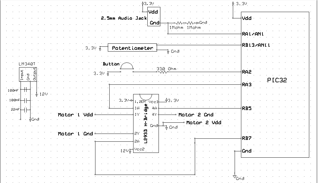
Schematic
Code
Main File: MeatCookerfinal.c
Approvals
The group approves this report for inclusion on the course website.
The group approves the video for inclusion on the course youtube channel.