
ECE 4760 – FINAL PROJECT REPORT
PORTABLE BRAILLE READER
Date: December 06, 2017
Mihir Marathe (mmm389)
Ashish Shinde (ahs278)
Introduction
“An e-Book Reader for the Visually Impaired”
We have designed a Braille Reader which is portable, easy to use for the visually impaired and also cost effective as compared to the current alternatives in the market. The user can access any text using Bluetooth, which is present in most modern cell phone products. We also provide features such as adjustable reading speed and going back in the text. Adjustable reading speed means that a single device can be used by the different users with variable level of familiarity with braille language. Going back in the text provides better control when the user needs to re-read the words in the text. Along with the device, we also design a debugger to aid in verifying and improving the design.
Literature Survey
Existing Devices
Figure 1: Traditional books Figure 2: Mechanical Readers
Figure 3: Refreshable Tablets
Traditional Books
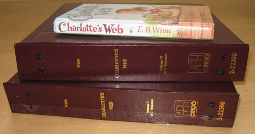
Only 4% of the books published appear in braille [1]. Moreover, a regular book for sighted people will span to multiple volumes when converted to a braille book. The reason being that there is no one to one mapping from regular characters to the braille characters. This results in traditional braille books being very large and not easy to carry around. For example, The Harry Potter and Goblet of Fire regular book has around 700 pages and costs around $10 , while the braille version has around 1000 pages and costs $167 [2].When we are using ultra thin gadgets such as iphones and laptops, specially abled people also deserve a device that facilitates reading and is portable and easy to use.
Mechanical Readers
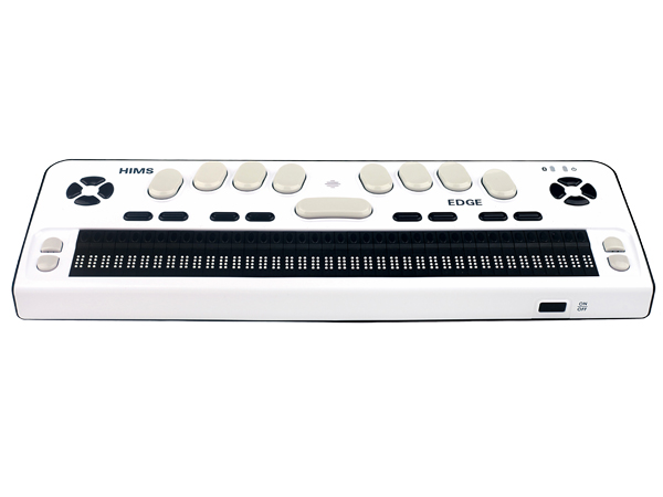
The mechanical readers such as the one shown in the Figure 2, costs $2195 and weighs around 4 kg [3]. Even though the devices such as these have lots of features, the cost and the product dimensions (14”x 9.5” x 5.5”) make these devices not ideal for personal use and can only be shared at places like school or offices.
Refreshable Tablets
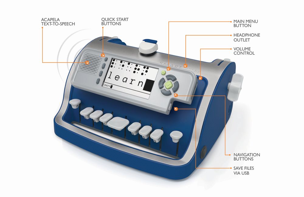
The tablet readers as shown in the figure 3, are definitely portable with lots of features to facilitate reading. But presently, the cost of these devices is very high [4] at around $2800, which makes these devices not suitable for people with financial constraints or institutions like schools or hospitals.
Audio books
Even Though, the audiobooks are not specific to blind people and are also used by the regular sighted users, most of the blind people prefer braille books for the same reason sighted people prefer paper books as compared to the audio books. Since reading is an experience and also a very important teaching tool that helps in the development of the cognitive ability, audiobooks can not be considered as an alternative to the traditional braille books.
Existing Patents
Currently we are not aware of any patents that would prohibit us from pursuing our design. There are certain patented designs by students which are different from what we are trying to build. Couple of such examples are Tactile from MIT and Dot from Korea.
Motivation
Given the existence of Braille readers already on the market (as shown above), the motivation for the project comes from a need to reduce a variety of parameters for the consumers. Reducing cost, form factor (size), power consumption, and ease of use while increasing product lifetime are all decent motivation to come up with a better implementation of what is essentially a portable braille reader. Given the prevalence of consumer electronics and cell phones in today’s consumer markets, integrating a cell phone into the implementation details makes sense from a ease of use perspective. Beyond improving performance and the other aforementioned parameters, providing visually impaired users with a small form factored, portable, and cell phone connected book reader will help bring more members of society into the electronic age even more so than before.
HIGH LEVEL DESIGN
Rationale
The reason for pursuing this project was the motivation gained from the background research and the desire to create something that will have high social impact. Moreover, the skills gained throughout the ECE 4760 gave us the confidence to undertake this project as most of the peripherals, protocols, threading and microcontroller libraries were already used and experimented with in the class labs.
Logical Structure
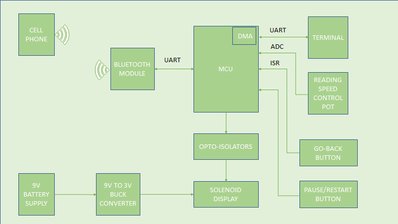
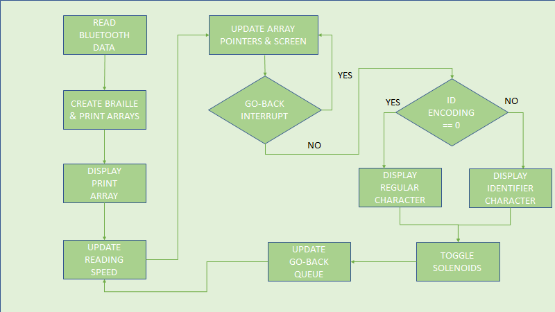
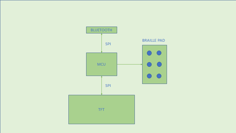
Figure 4: Design Flow-Chart
The flow-chart above highlights the peripherals used and the related protocols. The bluetooth on the device side communicates with the microcontroller using a UART communication protocol. Another UART channel is used to send the characters on the debugger terminal using DMA. An ADC channel is setup to connect the potentiometer which is used to adjust the reading speed. An external ISR is set up with the push button which is used to implement the go-back functionality. Another push button which is de-bounced in software, is used to control the overall design state. Finally, the solenoids are connected to the GPIOs using an Optoisolator protection circuitry. The entire design is battery powered with intermediate buck converters for stepping down the supply voltage.
Background Math
Our design did not involve any mathematical formulations. However, we needed to keep certain numbers such as average reading speeds, device dimensions, battery life in our minds to make sure that the end product is usable. The average reading speed of a braille reader is 90-115 words per minute. The average number of characters per word in english is 4.5. This leads to around 450 characters per minute. That means around 7 characters per second, which is unrealistic for our design as we only display a character the time. Therefore, we limit our design to a minimum speed of 30 characters per minute and a maximum speed of 240 characters per minute.
Hardware & Software Trade Offs
Our design did involve very careful consideration of hardware and software trade offs. For example, all the braille encoding could be done on the mobile application simplifying the microcontroller code and also reducing the microcontroller memory requirement. But we have decided not to implement this approach as it defeats the principle of abstraction. The braille encoding and decoding should be done on the device side while the cell phone application takes care of converting any file format to the plain text and transferring the data. Additionally, having external storage with the microcontroller does not require braille encoding to be done on the application side just for the purpose of memory.
DETAILED DESIGN
Hardware
Circuit Description
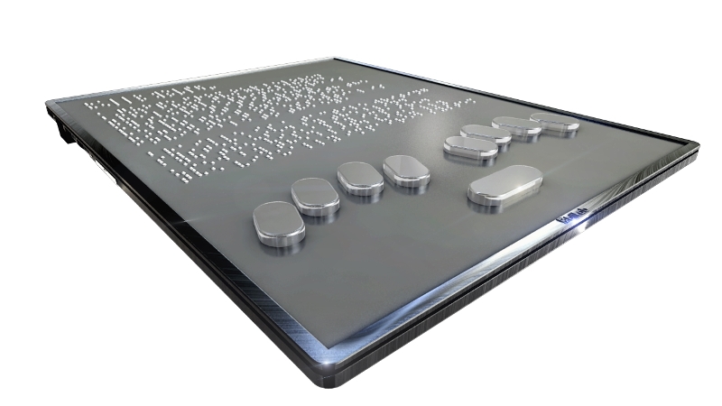
In order to actually create a 2x3 dot pattern which we could actuate at will, our top - level schematic consisted of the following components:
Physics of Solenoids
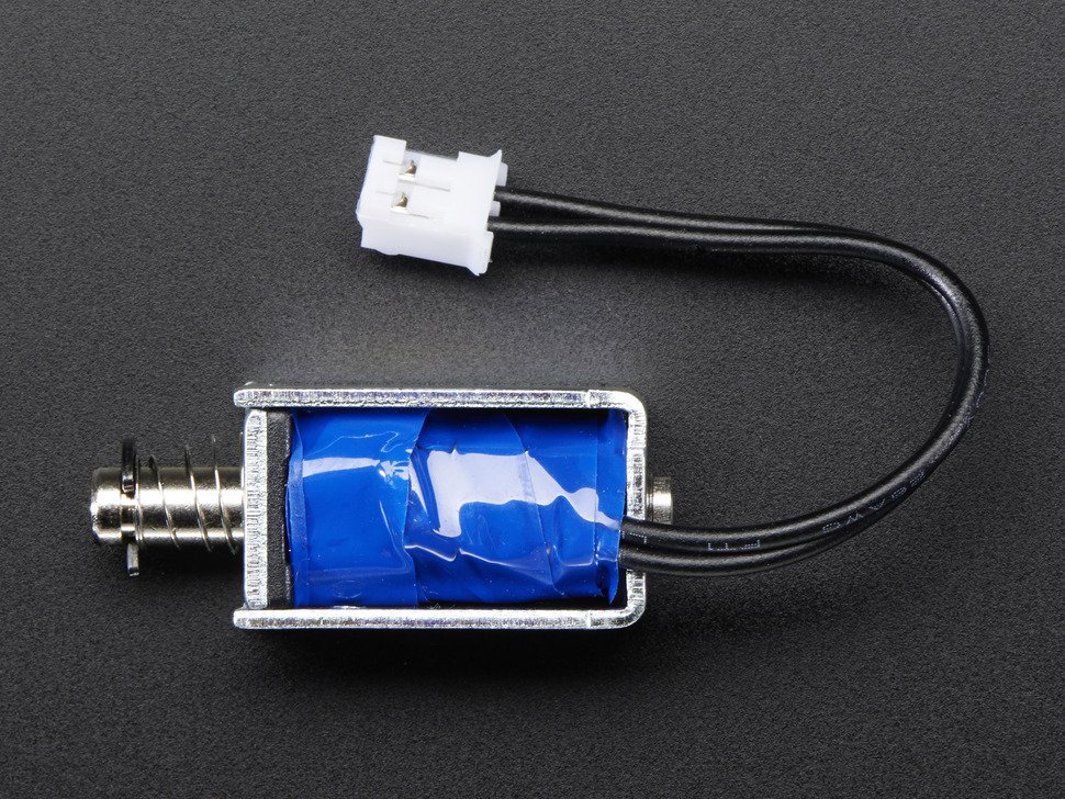
Our chosen method of braille dot actuation was the use of push-pull solenoids. The basic concept of a push pull solenoid is the following:
The magnetic force generated on the plunger must be greater than the sum of the gravitational force in the direction of the push vector, the spring force and the inherent magnetic force induced in the core itself in order to be actuated. The image below shows the specific push-pull solenoids we used for the actuation of the braille dots:
Figure 5: Push-Pull Solenoid
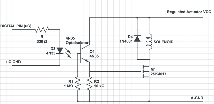
Solenoid Drivers
The driver circuits we created were essentially the same as described as in a previous lab’s (Lab 4) handout. In creating the motor control circuit, we brought in a digital TTL level line from the PIC to an optoisolator. This separates the ground for the microcontroller from the solenoid power and ground rails. Since the switching of the actuator is not at a high frequency (barely 4 Hz), we did not think we would need a spike absorption capacitor across the solenoid. When actuated, we did not see enough noise on the voltage rail (~3V) to warrant the use of a capacitor.
Figure 6: Driver Circuitry
We ended adding two protoboards to our design, each of which drove a set of 3 solenoids. We designed it such that each set of 3 solenoids was one row of braille dots, so as to simplify the physical build of the product. Each protoboard had three copies of the circuit shown above on it, and each protoboard required a slightly different regulated actuator VCC voltage due to slight mismatches in soldering and mismatches in the threshold voltages of the FETs used (despite being the same product number).
Power Supply Considerations
In designing our system, we realized that we had three separate voltage rail needs across the system: 5V for powering the Bluetooth module and PIC32 board (described below), 3.05V for the actuation of Protoboard 1, and 2.95 Volts for the actuation of Protoboard 2 (due to FET mismatches). Thus, we decided to use a power source that could be stepped down to all needed voltages while still supplying enough current to power all the loads. The closest standard voltage that could be easily used was a 9V battery.
In doing basic power calculations for the circuit, the most amount of power consumption was in the solenoid actuation itself. Since solenoids are essential inductors, the higher the actuation voltage we provided, the more current they would draw (in a steady state of actuation), and so we decided that we needed to find the minimum voltage which could actuate the solenoids (overcoming gravity and the spring force), while minimizing the current drawn from the supplies. In grouping the driver circuits in groups of three (per Protoboard), we found that the maximum steady state current drawn (when all three solenoids are actuated) was about 2.9A for both protoboards. Given that the actuation voltage for both boards was about 3V, we decided that our load had a 9W steady state consumption.
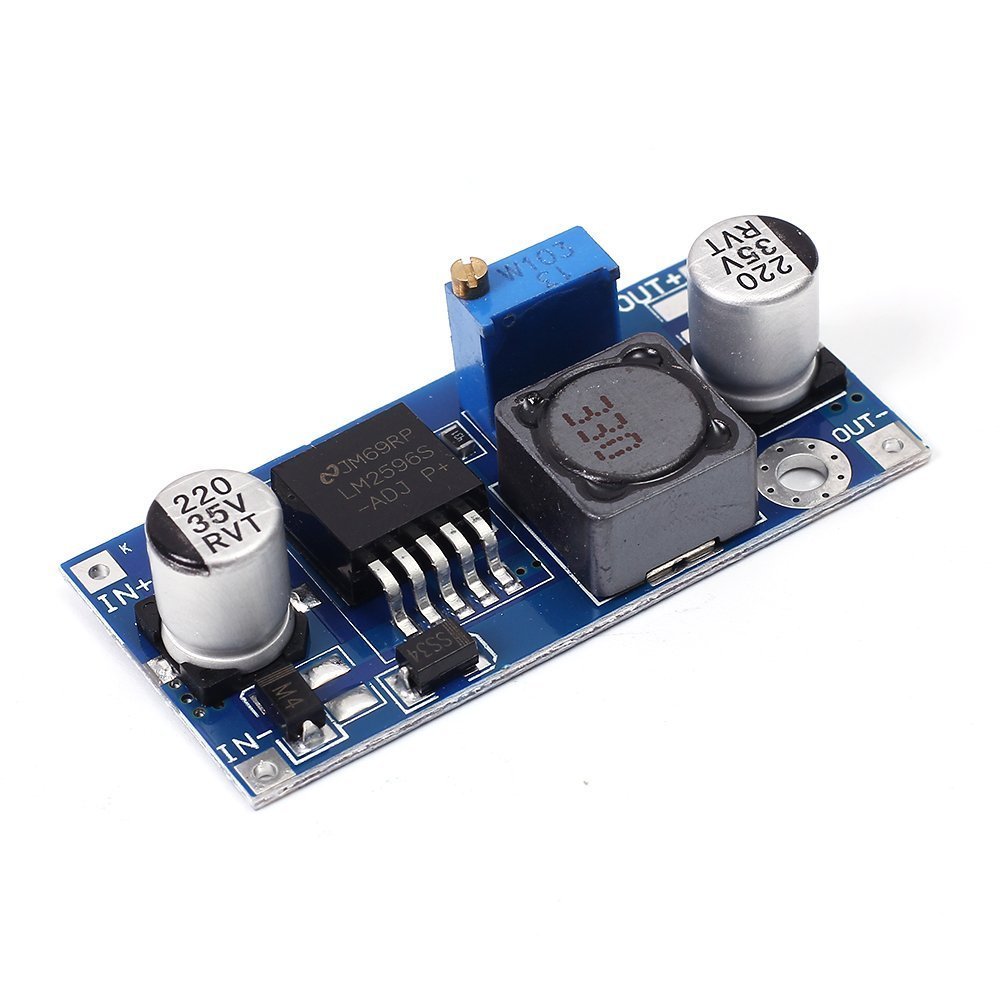
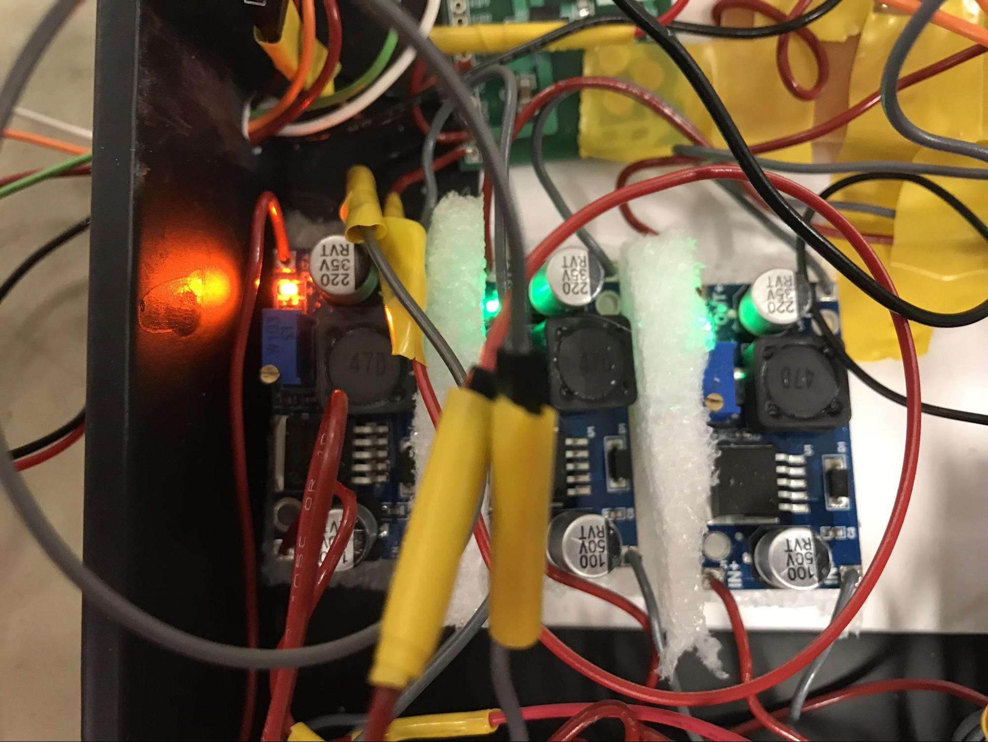
Thus, we needed to find switching buck converter boards which could handle an output steady state current of 3A and coud step down a voltage from the 9V supply down to the required 3.05 and 2.95 threshold voltages, and to the 5V supply needed for the Bluetooth module and microcontroller. After searching online, we settled on using the LM2596 SMPS dev boards (shown below) from RioRand, which could take in a dynamic range of 1.23 - 30V and output voltages up to 29V, with a maximum output current of 3A. They were also small form factored (dimensions: 45x20x14 mm) and had a settable output voltage.
Figure 7: LM2596 DCDC Board
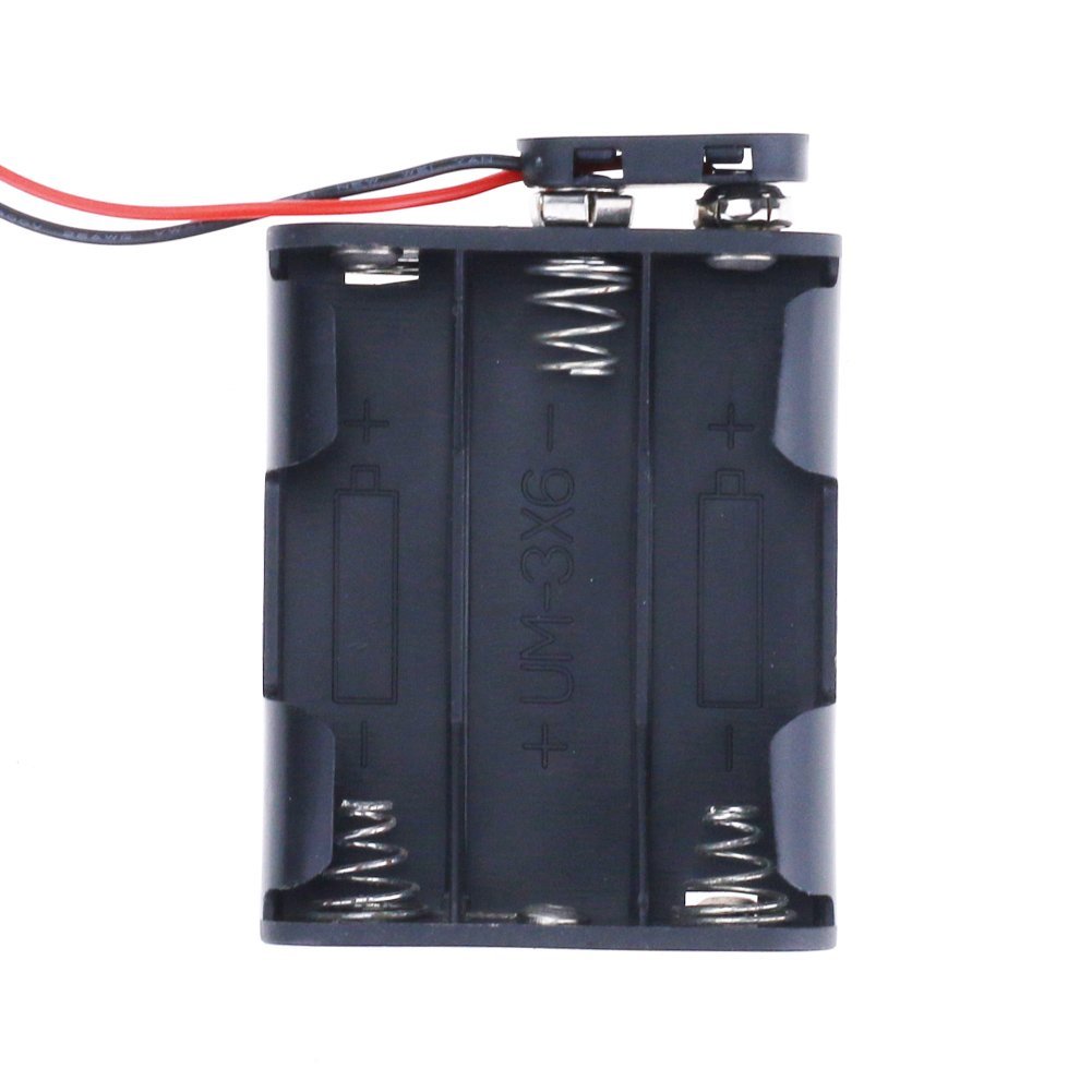
Given that we had three system voltage rails, we decided to double our power supplies so as to increase the lifetime of our device. In doing so, we increased the form factor of the project by the size of one 9V battery. However, in order to supply enough current and increase the lifetime of the system, we had to change the solenoid supply to a battery pack holding 6 AA batteries in series (which is still supplying ~9V, but with a higher mAh rating). The pack shown below is the one used for both the bluetooth/microcontroller and regulator board and the solenoid voltage rail regulator boards.
Figure 8: 6 AA Battery Holder
The current draw of the microcontroller and bluetooth was under 700 mA, and so we could have used a discrete 9V battery for that 5V rail regulator board. The system performed fine with this power supply setup.
ADC
The ADC is used to convert the change potentiometer resistance to the equivalent reading speed. The ADC setup is explained below.
The ADC setup can be split up into five parameters to simplify the program.
By using ADC_CLK_AUTO, the conversion trigger source is controlled by the ADC clock instead of manual or external interrupt. Conversion trigger indicates the end of SHA (Sample and Hold Amplifier) acquisition time and start of the binary value conversion time.
We set the auto sampling at the end of conversion period off and sample only by using the AcquireADC10(). The SHA period and conversion period puts the limit on how fast ADC sampling can be used. We sample ADC every 50 ms, which meets this period requirement.
#define PARAM1 ADC_FORMAT_INTG16 | ADC_CLK_AUTO |
ADC_AUTO_SAMPLING_OFF
The second parameter sets the ADC reference voltage and disables the offset test and scan mode. Since we have only one analog input, we set the scan mode off and one ADC conversion per sample period i.e. one sample per interrupt. For multiple analog inputs, the scan mode on with appropriate samples per interrupt should be selected or certain analog inputs will not be sampled.
#define PARAM2 ADC_VREF_AVDD_AVSS | ADC_OFFSET_CAL_DISABLE |
ADC_SCAN_OFF | ADC_SAMPLES_PER_INT_1 | ADC_ALT_BUF_OFF |
ADC_ALT_INPUT_OFF
The third parameter sets the conversion clock source, conversion clock select bits and ADC sample time.
#define PARAM3 ADC_CONV_CLK_PB | ADC_SAMPLE_TIME_5 |
ADC_CONV_CLK_Tcy2
The fourth parameter sets the particular input pin in the analog mode.
#define PARAM4 ENABLE_AN11_ANA
The fifth parameter disables the scan all mode and only samples the selected analog input.
#define PARAM5 SKIP_SCAN_ALL
Finally, the ADC channel is opened and enabled as follows.
SetChanADC10( ADC_CH0_NEG_SAMPLEA_NVREF |
ADC_CH0_POS_SAMPLEA_AN11 );
OpenADC10( PARAM1, PARAM2, PARAM3, PARAM4, PARAM5 );
Inside the serial thread, we read the ADC value as,
reading_speed = ReadADC10(0);
Depending on the value of reading_speed, we set the LPM_DELAY (Letters per minute delay) parameter to 2000 (30-LPM), 1000 (60-LPM), 500 (120-LPM) and 250 (240-LPM).
DMA
We use DMA to blast the braille text which is appended with the required identifier characters from PIC memory to UART2 Tx register (memory to peripheral).
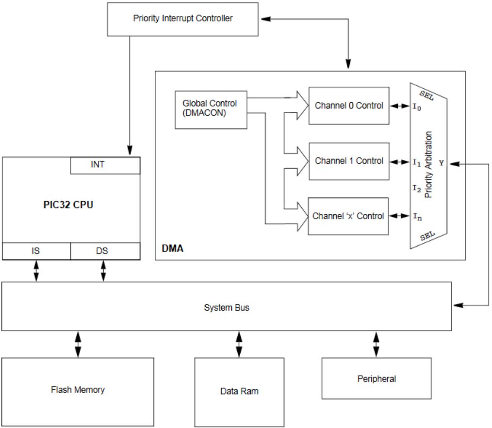
The block diagram of a DMA with respect to PIC32 can be seen in the figure below.
Figure 9: DMA Hardware Structure
As we can see from the block diagram, DMA can operate independent of PIC32 CPU and shares the memory and peripherals with the processor through a system bus. The DMA can transfer data at very high rate (3.2 Mbps) from memory to memory or memory to peripheral. As shown in the figure, DMA has multiple channels which are scheduled based on the priority arbitration. Multiple channels can be used to simplify the program running the DMA.
We open the DMA channel 1 in pattern match mode i.e. the DMA transfer stops when a null character (0x00) is detected.
DmaChnOpen(DMA_CHANNEL1, DMA_CHN_PRI2, DMA_OPEN_MATCH);
DmaChnSetMatchPattern(DMA_CHANNEL1, 0x00);
We want the DMA transfer to start when UART 2 Tx interrupt is triggered. Following parameters set the DMA transfer start and end events.
DmaChnSetEventControl(DMA_CHANNEL1,DMA_EV_START_IRQ_EN|DMA_EV_MATCH_EN|DMA_EV_START_IRQ(_UART2_TX_IRQ));
We set the DMA source as PT_send_buffer (which is copied from print_array[]), destination as UART 2 Tx register; source, destination and cell size in bytes as follows.
DmaChnSetTxfer(DMA_CHANNEL1, PT_send_buffer+1, (void*)&U2TXREG, max_chars, 1, 1);
The interrupt is triggered when the DMA transfer is done. This flag is used to yield inside a thread.
DmaChnSetEvEnableFlags(DMA_CHANNEL1, DMA_EV_BLOCK_DONE);
Finally, the DMA transfer is started when UART 2 Tx is ready as follows,
DmaChnEnable(DMA_CHANNEL1);
UART
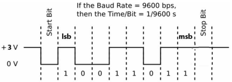
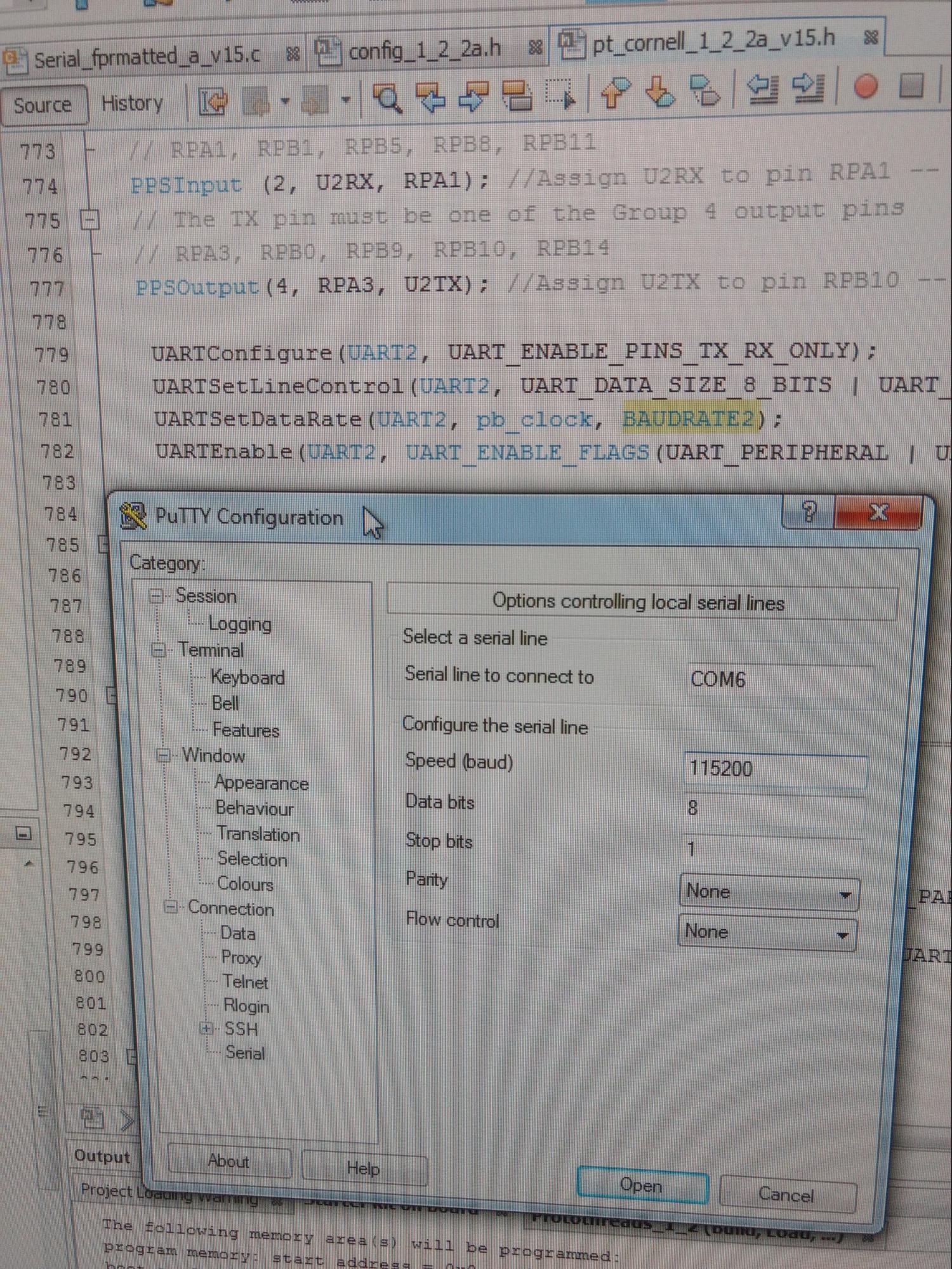
The Universal Asynchronous Receiver Transmitter (UART) is a full-duplex, asynchronous serial communication protocol. We use two UART channels, one to connect with the bluetooth module and other to connect with the putty terminal using a USB to UART serial cable. The UART hardware can be used in 8-bit or 9-bit mode, both have one start and one stop bit. The 9-bit mode is used for multi-processor communication where the bit-9 suggests if the data being transferred is a data byte or address byte. The diagram below shows that the data is transferred from LSB to MSB followed by a start bit and terminated with a stop bit for the baud-rate of 9600 bps.
Figure 10: UART Data Transfer
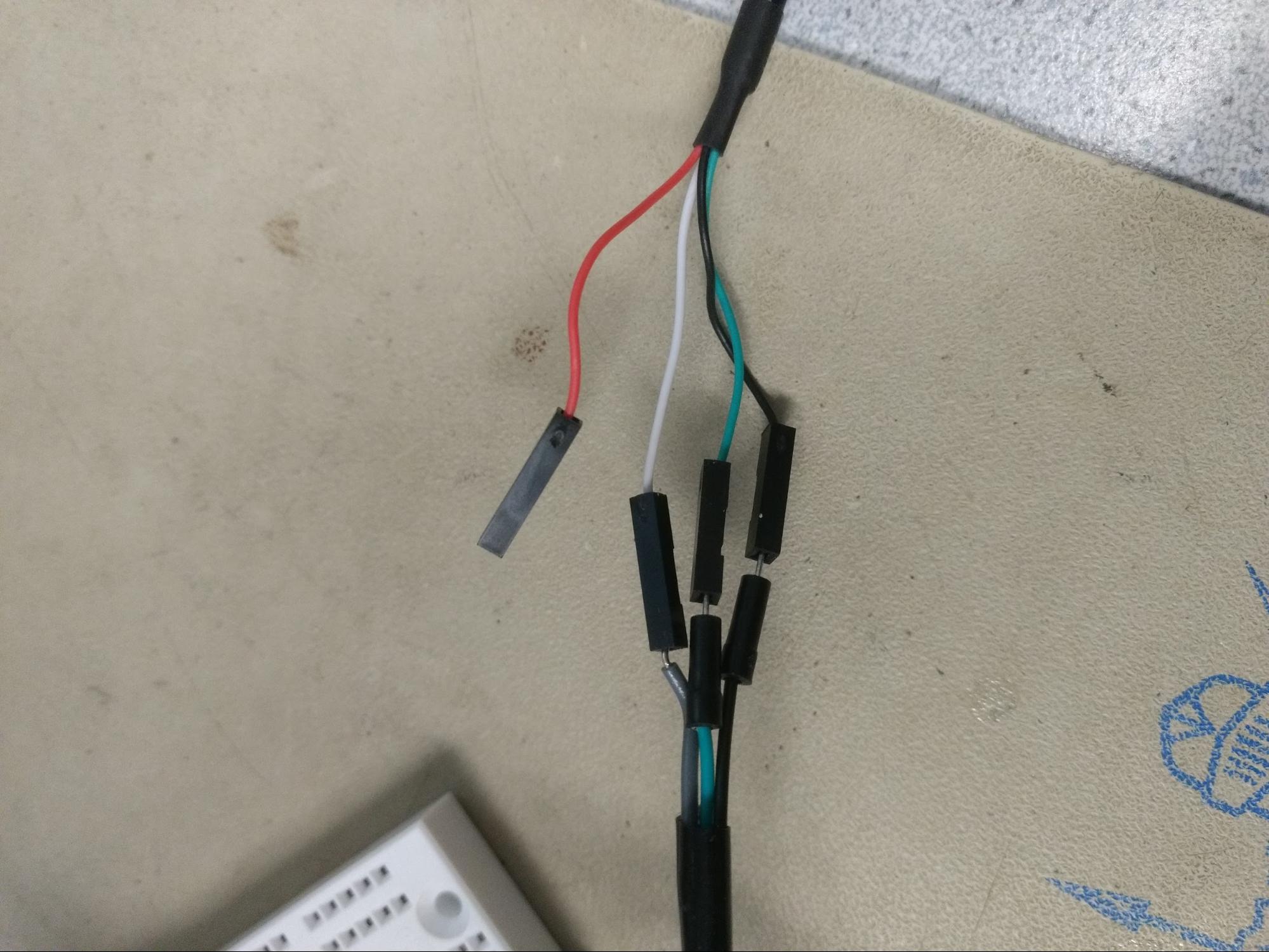
To update the terminal real time using UART, we use higher baud-rate, 115200. We use no parity bits and flow control. So each data transfer consists of sending 10-bits for around 86 uS. While the UART for bluetooth is set up at baud-rate of 9600 as required by the bluetooth module. The USB to UART green wire is connected to UART Rx pin, white wire is connected to UART Tx pin, black wire is connected to microcontroller ground and the red wire is left unconnected. Following figure shows this connection and putty serial terminal settings.
Figure 11: Serial Cable and Putty Settings
The Serial thread spawns PT_GetSerialBuffer and PT_DMA_PutSerialBuffer threads. The PT_GetSerialBuffer thread gets the bluetooth data from the UART 1. This thread first waits until the UART 1 receiver is ready.
PT_YIELD_UNTIL(pt, UARTReceivedDataIsAvailable(UART1));
The received character is stored in PT_term_buffer[] until the bluetooth data end is detected.
The PT_DMA_PutSerialBuffer thread waits until UART 2 transmitter is ready and enables the DMA channel 1.
PT_YIELD_UNTIL(pt, UARTTransmitterIsReady(UART2));
DmaChnEnable(DMA_CHANNEL1);
The thread then waits until the DMA pattern match interrupt is detected.
PT_YIELD_UNTIL(pt,DmaChnGetEvFlags(DMA_CHANNEL1)&DMA_EV_BLOCK_DONE);
EXTERNAL INTERRUPT
There are total five external interrupts supported, INT0 to INT4. Of these, INT0 maps to the pin 16 which is not remappable while INT1 to INT4 are remappable. In order to simplify the pin mapping, we use INT1 instead of INT0.
The INT1 is configured as follows,
ConfigINT1(EXT_INT_PRI_2 | RISING_EDGE_INT | EXT_INT_ENABLE);
This interrupt is used to implement go-back functionality in the text by mapping it to a push button on digital input pin.
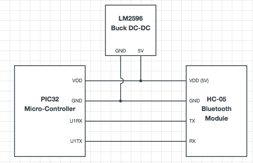
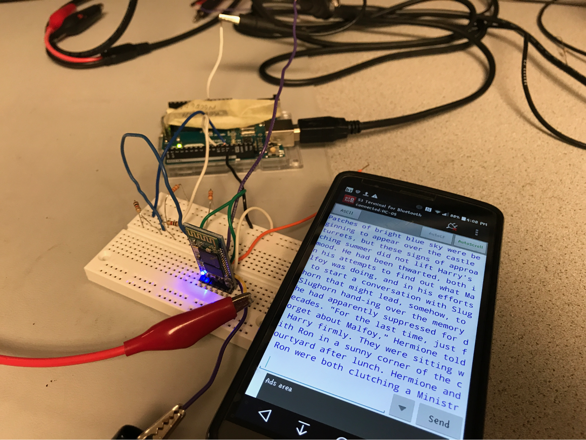
BLUETOOTH
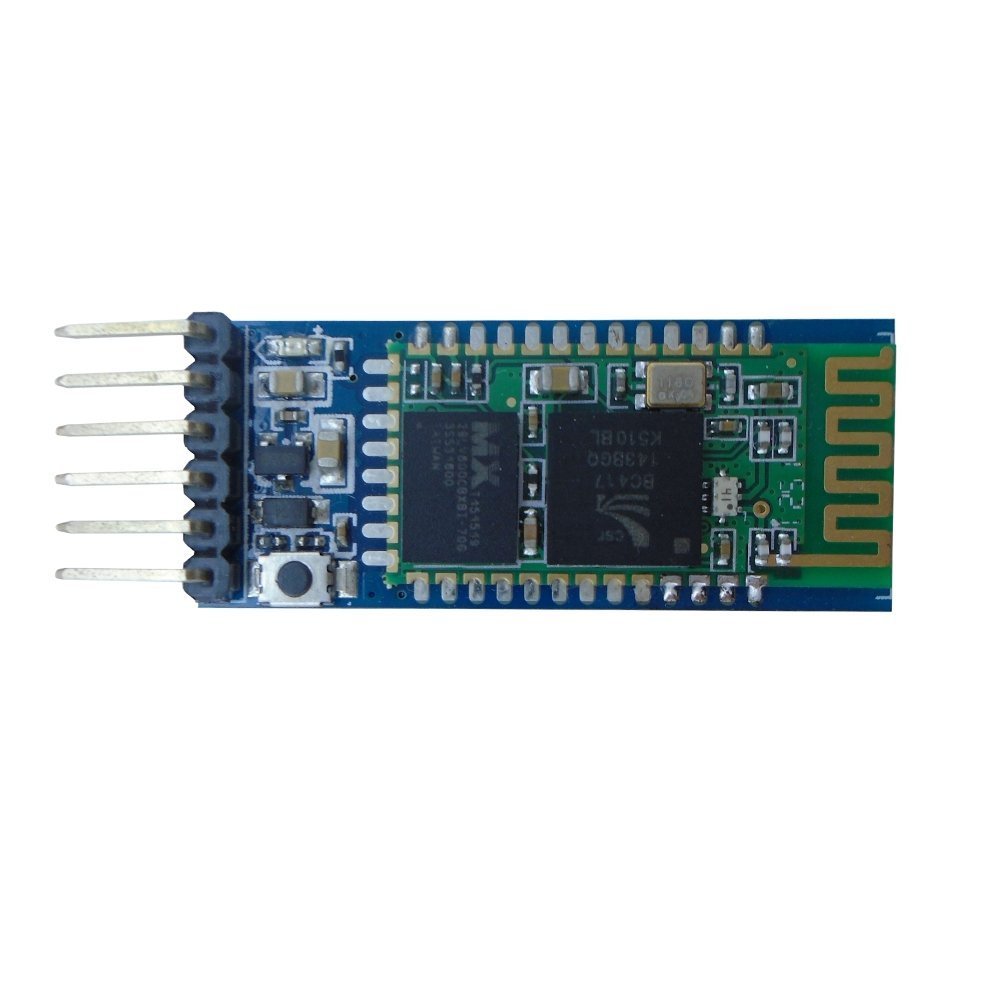
We knew that we wanted to connect the system to a cell-phone via bluetooth, and so we chose a very simple protocol and hardware to implement it. We found several free applications for Android which can connect to HC-05 Bluetooth Modules, which make the bluetooth protocol look like a serial communication port to both the microcontroller and to the application itself. Since this type of module had been used by previous groups in other projects, we were confident in our ability to use it with relative ease. The connection itself was very simple, shown in the figure below. Upon power up, we were able to connect to the bluetooth module (labeled as HC-05) from a standard Android Phone, and using the S2 BT Term application, were able to send data to the microcontroller via UART. Given the fact that the data was being sent over UART, we had to convert a pdf file sample (during Testing) to a .txt file which is represented as a UNICODE character set, which made storing it on the microcontroller very easy (as described in the UART descriptions). We encoded a echo of the transmitted data to be sent back to the phone to verify that transmission of the text file was successful, as a top level visual acknowledgement.
Figure 12: Bluetooth HC-05 Module Used
Figure 13: Bluetooth Module to PIC Connection (with Power)
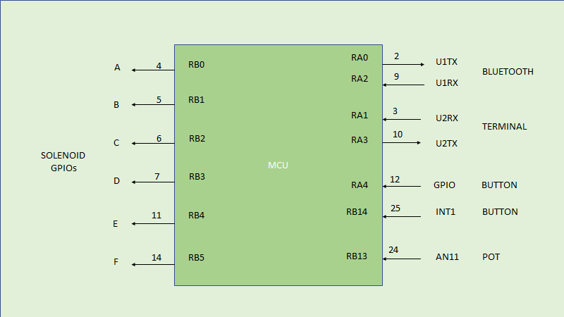
Pin Mapping
Figure 14: MCU Pin Mapping
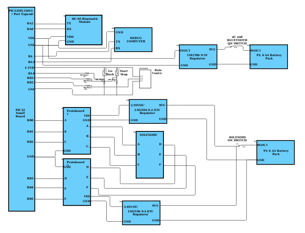
Schematic
The following schematic is our top level system schematic, using the components aforementioned.
Figure 15: Top-Level System Schematic
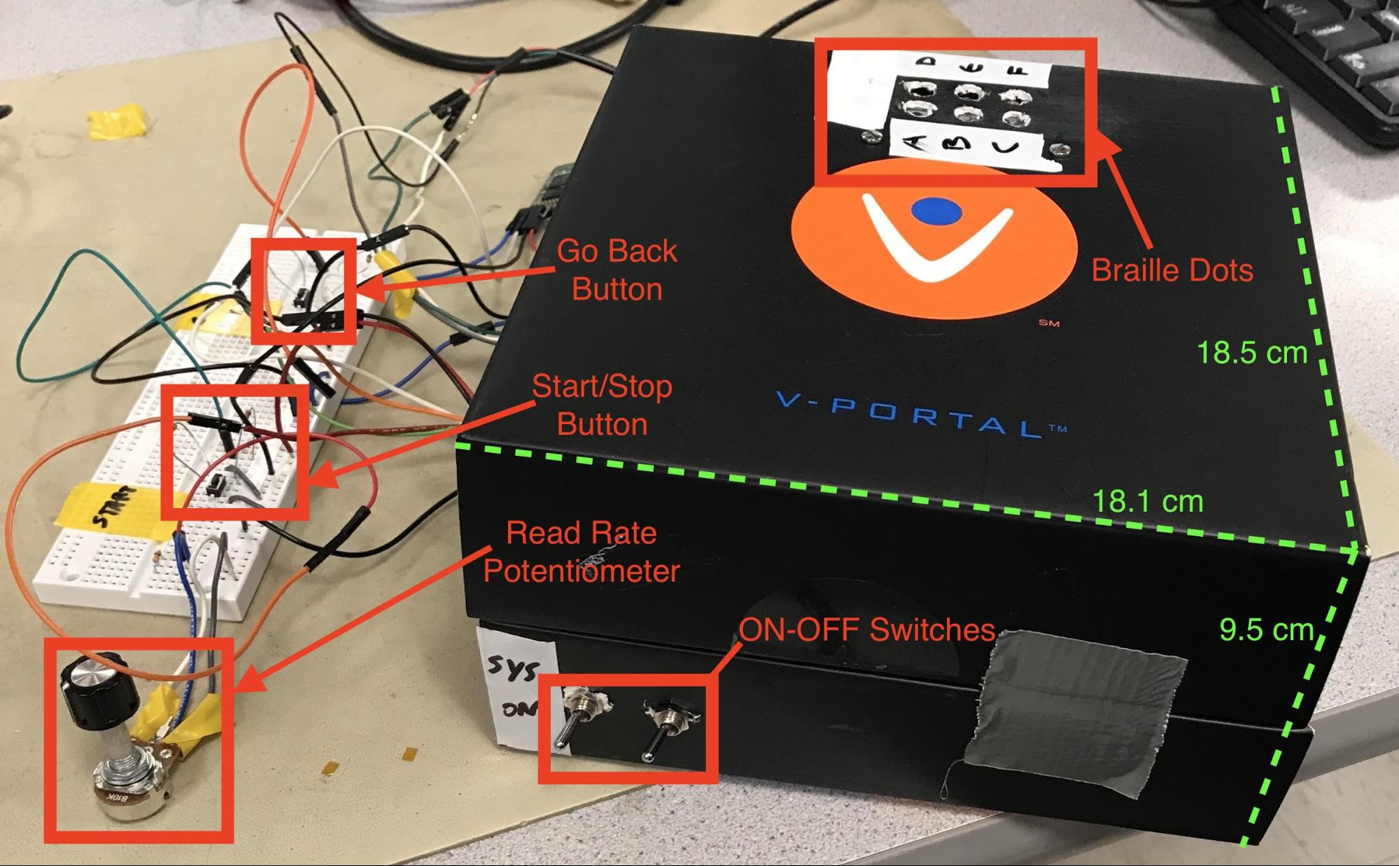
Mechanical Design
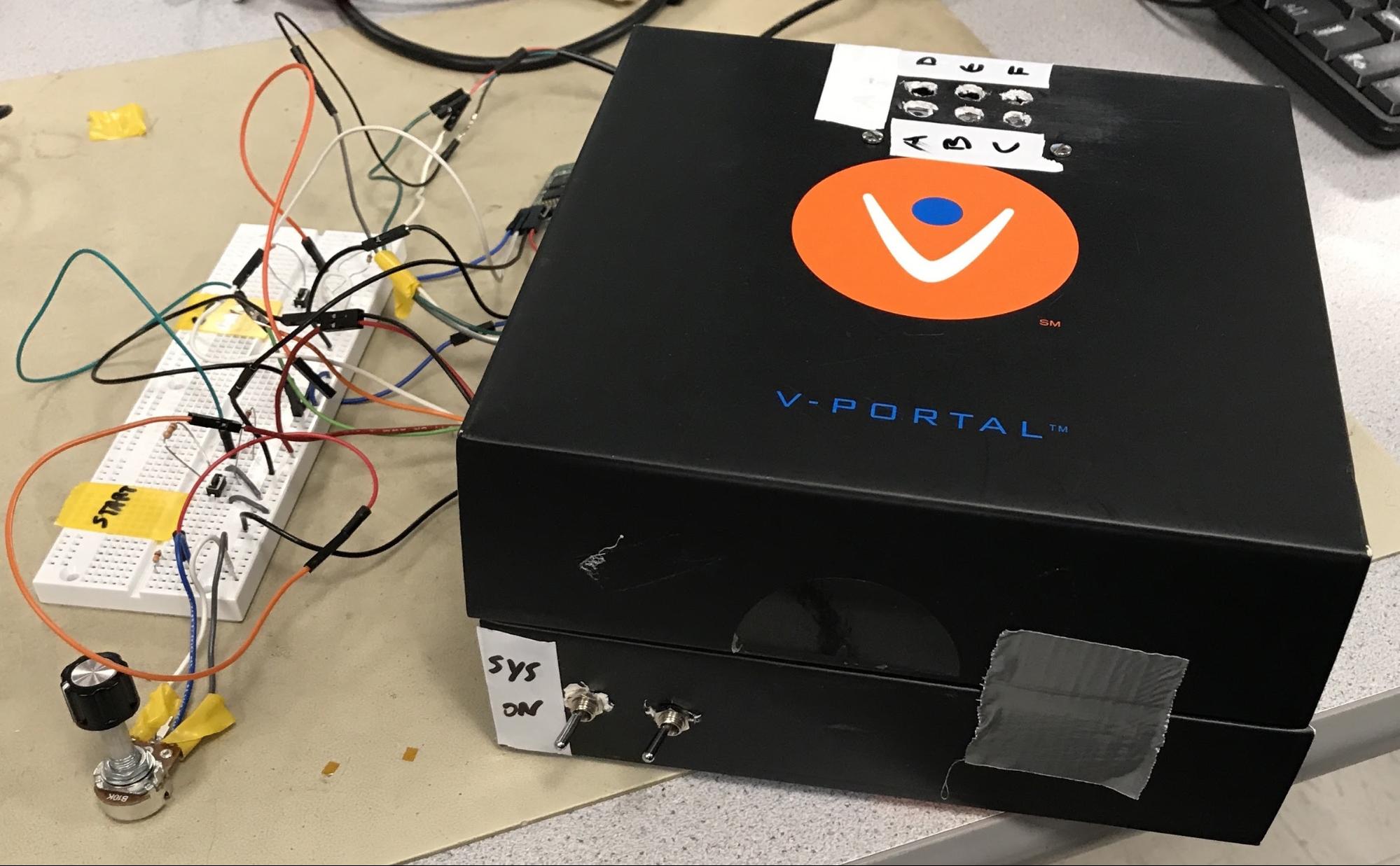
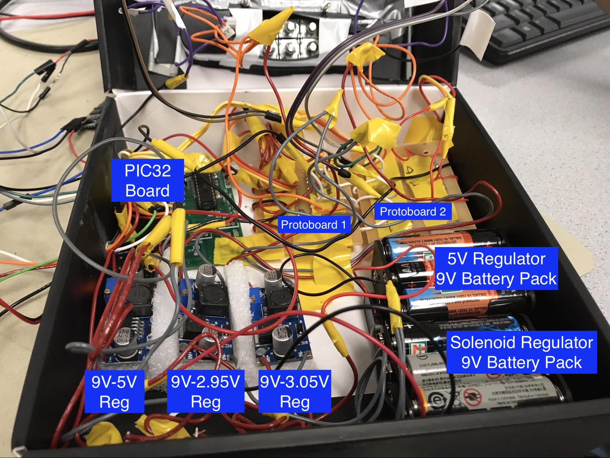
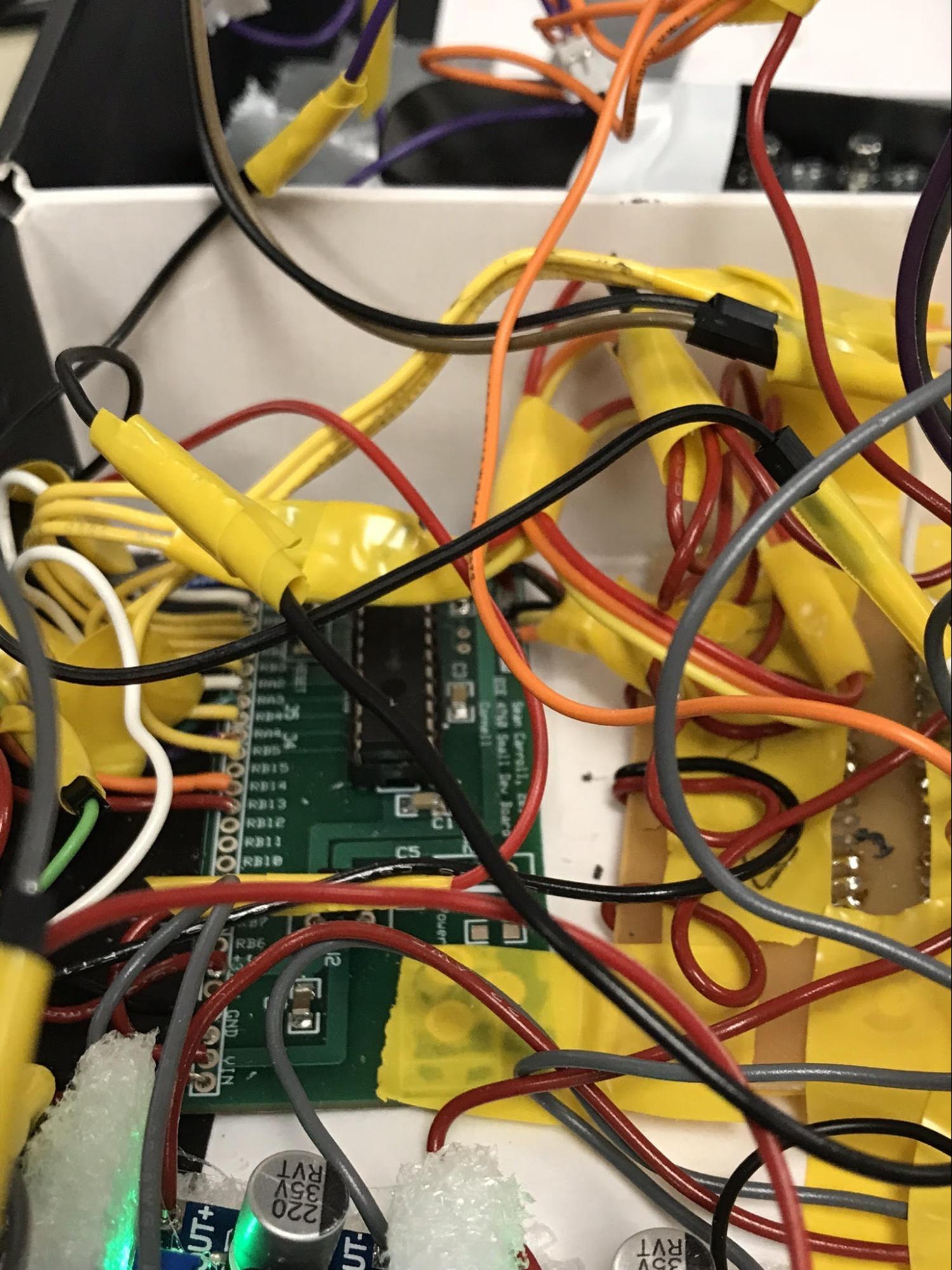
The general assembly of the project is shown below. We fit most of the circuitry, including the microcontroller board (assembled on the small dev board, given by Bruce Land), the two Protoboards, all three switching DC-DC regulator boards, two battery holders, the six mounted solenoids, and the two power supply switches into an enclosure box. The box was repurposed from an old phone modem product (found as scrap). The two buttons, the bluetooth module, and potentiometer were placed outside the box for ease of use. There was sufficient space inside the box, but since this was a proof of concept, and because the wiring setup inside the box became very fragile and difficult to work with, we decided to leave that circuitry outside the box (for the sake of time). The final box dimensions (ignoring external circuitry, since it could fit inside the box) was 18.5 x 18.1 x 9.5 cm. The following images show the individual solenoids connected together, along with some of the internal placement of the circuit components.
Figure 16: General Box Setup
Figure 17: Internal Components and Wires
The components embedded into the walls of the box are ON-OFF Switches, which are secured via a nut and washer fastening. They control the battery connection state to the voltage regulators.
Software
Braille Encoding
All the encoding from english alphabets to braille alphabets is done as per the braille standard. As per the standard, most of the english characters (alphabets, digits, special characters) are encoded as a single braille character. But there are certain special characters and special scenarios which are encoded as two braille characters. For example, lowercase characters (a-z), uppercase characters (A-Z) , digits (0-9) and some special characters (: , . ! ? ;) are encoded as a single braille character. Whereas, special characters such as (& @ ~ < > { } [ ] ( ) # + etc) each are encoded as two braille character where first character represents the Identifier character (which is unique for every character) and the second character represents the actual character.
For example,
: is represented as :
But
& is represented as I&
(Here I represents a unique identifier character and not an upper case ‘I’).
Moreover, every time there is an uppercase character, we need an identifier character. An identifier character is also needed for a digit. However unlike uppercase characters, a sequence of multiple digits will have only one Identifier character. For example,
ABC is represented as IAIBIC
While
415 is represented as I456
Additionally, whenever there is a transition from a digit to a lower case character, an identifier character is required. For example,
5abc is represented as I5Iabc
The space character has special encoding as represented as an absence of character.
Note that this encoding is sufficient to legibly read any grade-I braille text. There is a lot more encoding for underline characters, italic characters, bold characters etc. However, we are ignoring this as current encoding is sufficient to explain the proof of concept.
Algorithm
The algorithm used is explained in the high level diagram below.
Figure 18: The Algorithm
As explained in the previous section, there are many different scenarios where we need to add an identifier characters to the raw character array. Therefore, we need a way to differentiate between a regular character and an identifier character. One way of doing it was to map all the characters and scenarios that need and do not need identifier characters to unique integers and convert the raw character array to mapped integer array. However, this makes the code lengthy and unreadable. Therefore, we decided to use an array of structs.
The struct is defined as follows.
struct braille_map {
int id_encoding;
char braille_char;
};
The first field contains the encoding value and second field contains the character. The threads protothread_create_array and protothread_update_array modify these two field by checking each character in raw array along with all the different scenarios.
The first field id_encoding can have following values.
id_encoding | Scenario |
0 | No identifier character is needed, braille_char field is displayed as it is |
1 | Represents a special char, Unique identifier character is displayed depending on the braille_char field |
2 | Represents a digit to lowercase transition, Unique identifier character is displayed but braille_char field is ignored |
3 | Represents a digit, Unique identifier character is displayed but braille_char field is ignored |
4 | Represents an uppercase character, Unique identifier character is displayed but braille_char field is ignored |
For example, the character ‘a’ is encoded as id_encoding = 0, braille_char = ‘a’. While the character ‘A’ is first encoded as id_encoding = 4, braille_char = ‘A’ and then id_encoding = 0, braille_char = ‘A’. Similarly, the character ‘&’ is first encoded as id_encoding = 1, braille_char = ‘&’ and then id_encoding = 0, braille_char = ‘&’.
Since the DMA can not blast out the data from an array of structures, to display the text on the terminal, we need a separate character print_array[]. In the print_array[], every identifier character is encoded as ‘I’ and displayed on the terminal with different color to differentiate it from the regular uppercase ‘I’ character. This represents the create arrays and display arrays section of the algorithm in the figure above.
Go-back ISR
If at any point during the reading, if the user misses certain characters or words we provide two controls to help the user. User can change the reading speed by using the knob or press the go-back button which takes the user four words back in the text. When the go-back button is pressed, it is important that the control is transferred to the start of the word and not any random character in the word. In order to implement this, we implement a Queue like data structure with a five element queue. Where each entry in the queue holds the index of start of previous four words respectively. The thread protothread_forward pushes the word indexes in the queue. When the queue is full, the older index is popped out and the new index is pushed in. When the go-back ISR is triggered, the control is transferred to the index at the first element in the queue.
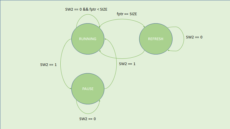
Control FSM
The control FSM can be explained in the figure below.
Figure 19: Design FSM
The entire design operates in three states; Running, Paused and Refresh. All the three states are controlled by a multi-state button (sw2). Pressing the sw2 in Running state puts the design in Paused state and vice versa. When the user reaches the end of the text, the design is in the Refresh state and pressing the sw2 again puts the design in the Running state. In order to prevent accidentally changing the states, we need to debounce the sw2.
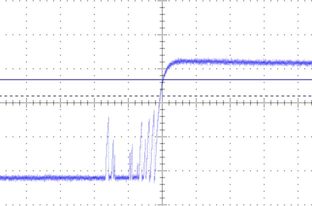
When a mechanical switch is pressed or released, the output logic value does not resolve instantaneously to a clean logic low or logic high. This can be understood/seen by looking at the figure below, taken from the internet.
Figure 20: Switch Debouncing
When a switch is pressed, the output oscillates between logic high and logic low before settling to the final value. So as long as the analog voltage is greater than VOH, the digital output will be considered as logic high and we will get multiple output logic high voltage as the signal transitions. The debouncing can be taken care of in hardware by using a capacitor or in software by using a FSM.
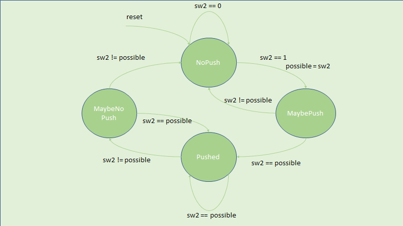
Debouncing FSM
For most of the mechanical switches, 30 ms is considered to be the sufficient time to allow output voltage to settle to a definite logic level. Since the protothread_serial has to yield 50 ms due to ADC read, it is good enough for the debouncing FSM. The FSM is shown in the figure below. The FSM has four states, NoPush, MaybePush, Pushed and MaybeNoPush. Upon reset, we start in NoPush state. We stay in NoPush state as long as the sw2 is 0. If the sw2 is 1 and we are in NoPush state, then there could be a possible push and we record the value of button push as a possible value and transition to MaybePush state. After 50 ms later, if the sw2 returns a value equal to possible, then there was a definite button push and we change the design state (Running, Paused or Refresh) and move to the Pushed state, else we transition to NoPush state. When in the Pushed state, if sw2 returns a value equal to the possible value, then we stay in the Pushed state or else we transition to the MaybeNoPush state. After 50 ms later, if the sw2 is still equal to the possible value, then the button was not released and we transition back to the Pushed state else we transition to NoPush state and repeat the process again.
Figure 21: Debouncing FSM
Solenoid Toggling
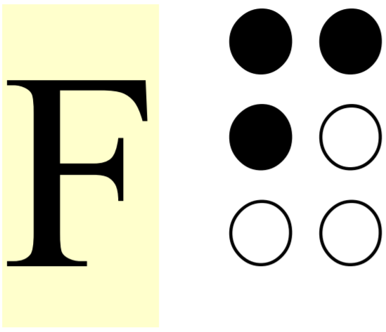
We use six GPIO Port B pins set as output for the six solenoids. The solenoid ports are defined as,
BIT_0 as A BIT_1 as B BIT_2 as C
BIT_3 as D BIT_4 as E BIT_5 as F
Where the display is defined as,
A D
B E
C F
For example, ‘F’ is represented by setting A, B, D high, and resetting C, E, F solenoids to default positions.
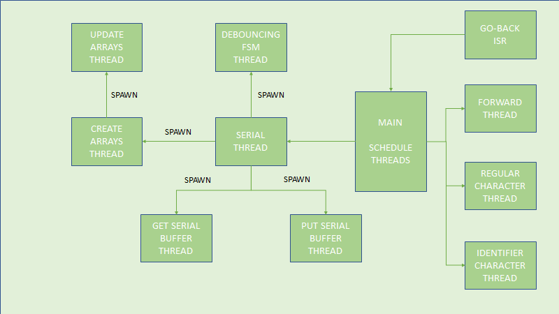
Thread Structure
Figure 22: Thread Structure Flow-Chart
ISSUES FACED
The following is a list of issues we faced and corrected throughout the process of our project.
Functions can be used with protothreads but they can not have any protothread routines such as protothread delay. We initially had functions with protothread delays which did not work as protothreads are stackless and function can not be pushed on to the stack. We converted everything to threads with protothread spawn and it worked.
We were initially spawning the braille display threads from the forward thread. This resulted in the delay between terminal and braille reader. In order to synchronise the terminal and braille reader, instead of spawning the braille display threads, we used protothread yield which solved the synchronisation problem.
C does not allow ternary compare. We faced this issue while comparing the adc value for the reading speed. For example, (0 < reading_speed < 250) will always result in true as C will first do the (0 < reading_speed) comparison which returns 1 and it is also less than 250. Therefore, in case of nested if-else comparisons, only the first condition is executed all the times and remaining conditions are never triggered.
Initially we were copying PT_term_buffer[] array to an intermediate array so that we can add the identifier characters to the raw array. But as the scanf(“%s”) is whitespace terminated therefore were not able to read beyond the first word. We tried to use fgets() which did not work. We solved this problem by eliminating the intermediate array and directly working with PT_term_buffer[].
In order to implement go-back queue, we needed to keep track of whitespace characters in the text. To perform whitespace comparison, initially we were using “ ”instead of ‘ ’. This did not work as “ ” is \0 terminated and always resulted in incorrect comparison.
The ISR in our program was getting triggered irregularly even if the button was not spaced. It turned out that we incorrectly mapped the INT1 to UART Rx pin. We solved this pin mapping confusion by creating a pin diagram as shown in the figure which saved our debugging time due to hardware connection errors.
7. Incorrect Delay for solenoids
Even after yielding the braille display threads(instead of spawning), the characters on terminal and braille reader were not synced. The reason was that the braille display threads were yielding twice as much as forward thread for ON state and OFF state of solenoids. We fixed this issue by adjusting the delay such that ON+OFF state delay is equal to the forward thread delay.
8. Same character toggling in Pause state
In the pause state, the braille reader did pause at the certain character but it also toggled the solenoids with the same character. We solved this problem by yielding braille display threads when the forward thread is also enabled.
9. Loose Connections When Wiring Protoboards to Solenoids
When wiring up the protoboards to the solenoids, we decided to use solid core wire connections to jumper cables, which required taping the connections between the wire and the jumper cable. Since these taped connections weren’t guaranteed to ensure contact between the metal contacts of the wires, there were many situations where our circuit became disconnected when attempting to route other wiring or when debugging. This could have been corrected by soldering multicore wire directly from the protoboards to the solenoids, but
10. Missing Ground Connections on Protoboards
When first constructing the protoboards, we ran into an issue where we forgot to solder a ground rail to the board, thus causing no actuation from the board. This took some time to debug, but when found, our assembled board functioned correctly in isolation.
11. Attempting to Connect L Angle Wires to Solenoid Plunger End
Our initial design idea was to decrease the distance between the assembled solenoid fixture such that the actuated dots could be felt with only one finger. The way to do that would be to affix an L angle wire to the surface of the solenoid, but this proved to be very difficult. Hot glue and solder was not able to get onto the surface of the solenoid plunger, and our final attempt with epoxy required a four hour curing time, which was not time efficient for us to perform. Thus we abandoned that design ideal for this iteration of the design.
TESTING
In designing and validating our design, we adopted an iterative and modular design strategy. We designed the various blocks in isolation and proceed to test them in isolation. After validation of module performance, we integrated components and validated them as well. The following are some notable realizations and performance we encountered during our development process.
During the creation of our power budget, we realized that the braille alphabet (in Braille I coding) did not actually actuate all 6 braille dots for any given symbol. Thus, we were able to decrease the number of battery packs and number of step-down regulators for the same lifetime by realizing that the max current of the entire system would not exceed 1.7A from the 9V batteries themselves, since each protoboard would pull a maximum of 3A (roughly), and that the upper bound on the current pull from the 9V supply was calculated as (5A*3V / 9V) = 1.7A, which is suppliable from the 6 AA battery pack topology.
When testing the various protoboards and power regulators, we tested the assembled structures for signal continuity and proper performance using the lab multimeters and oscilloscopes. Since all of our work was in the temporal domain, no measurements of frequency or specific sample rates were required.
In testing the solenoid drivers and solenoid structure, we ran a simple solenoid test toggling code to ensure that all of the driver channels worked and could be triggered off the microcontroller itself. The video of the test is documented in the following link: https://youtu.be/yOR04NSrE7s
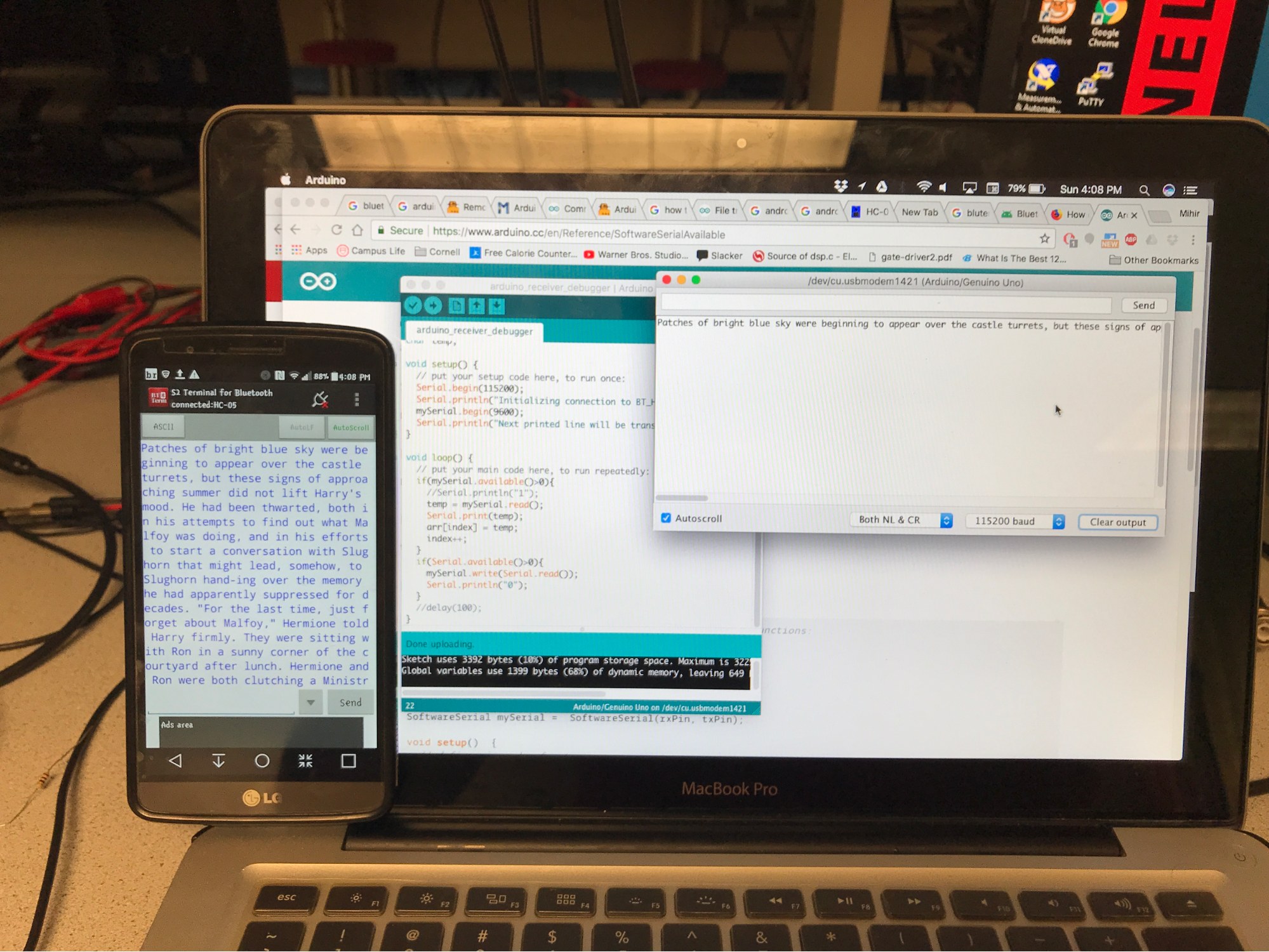
Prior to receiving the bluetooth module, we were able to test the system by just setting up a second UART channel to hook up to the putty terminal on our test desktop. Since we were only using the bluetooth module as a pass through device we were able to essentially use the same UART protocol as the debugger to actually send data to the microcontroller. This made bluetooth integration much easier.
We validated the fact that the bluetooth module would work as a pass through serial device on an arduino uno and tested it with the S2 BT Term application (for Android). We were able to prove that is worked the arduino (independent of the PIC32), and by doing so, during integration, we were able to hook it up to the PIC32 UART channel, set the appropriate baud rate, and the integration worked seamlessly. The following images show the phone with the bluetooth HC-05 Receiver, along with the phone next to the Arduino hooked up to the computer serial port receiving the sent data.
Figure 23: Bluetooth with Application
Figure 24: Application with Arduino Serial Monitor
RESULTS
In addition to the testing (intermediate) results and process shown above we were able to successfully achieve our goal of generating braille dots via the text file received via bluetooth, along with performance control, with control buttons and a read rate adjusting knob (potentiometer).
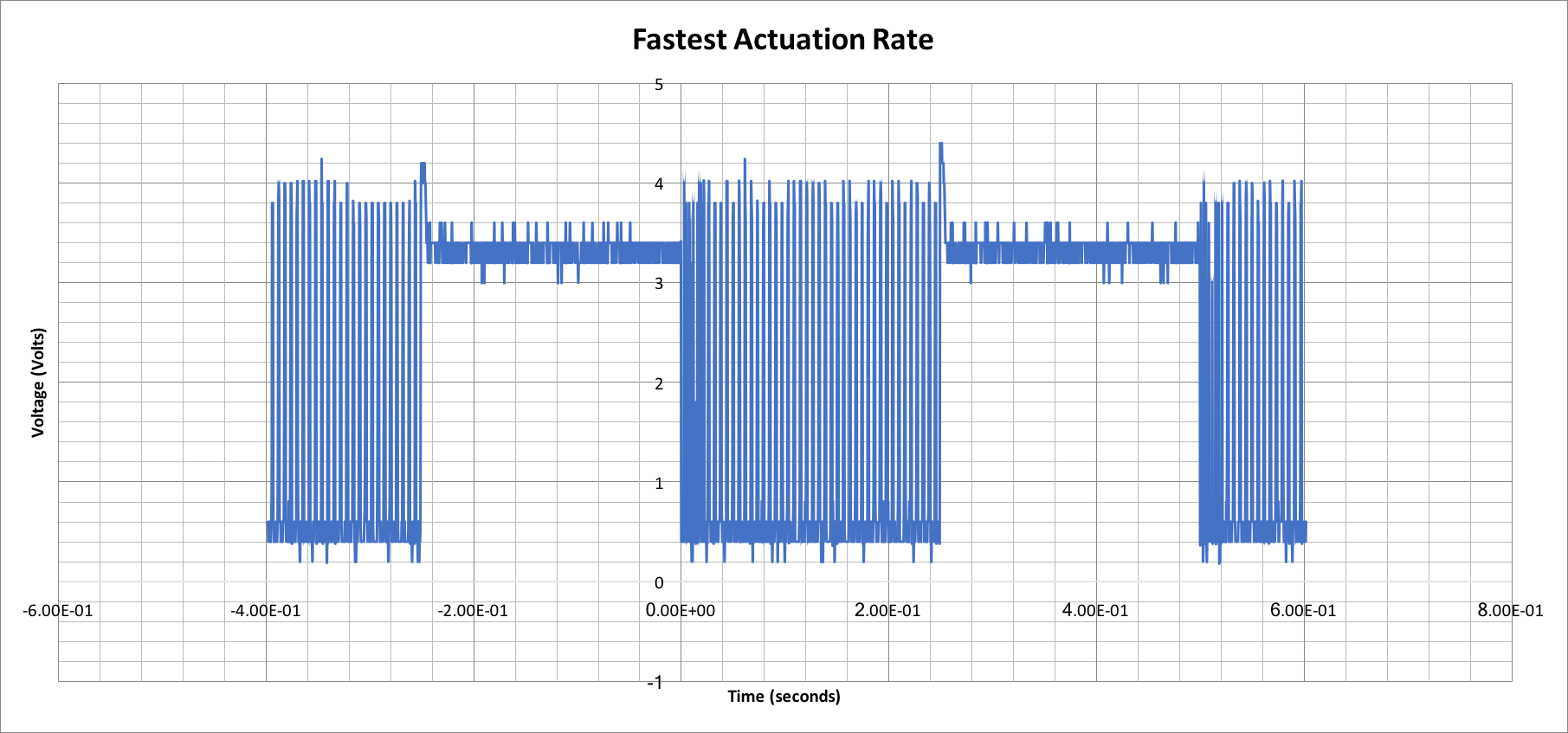
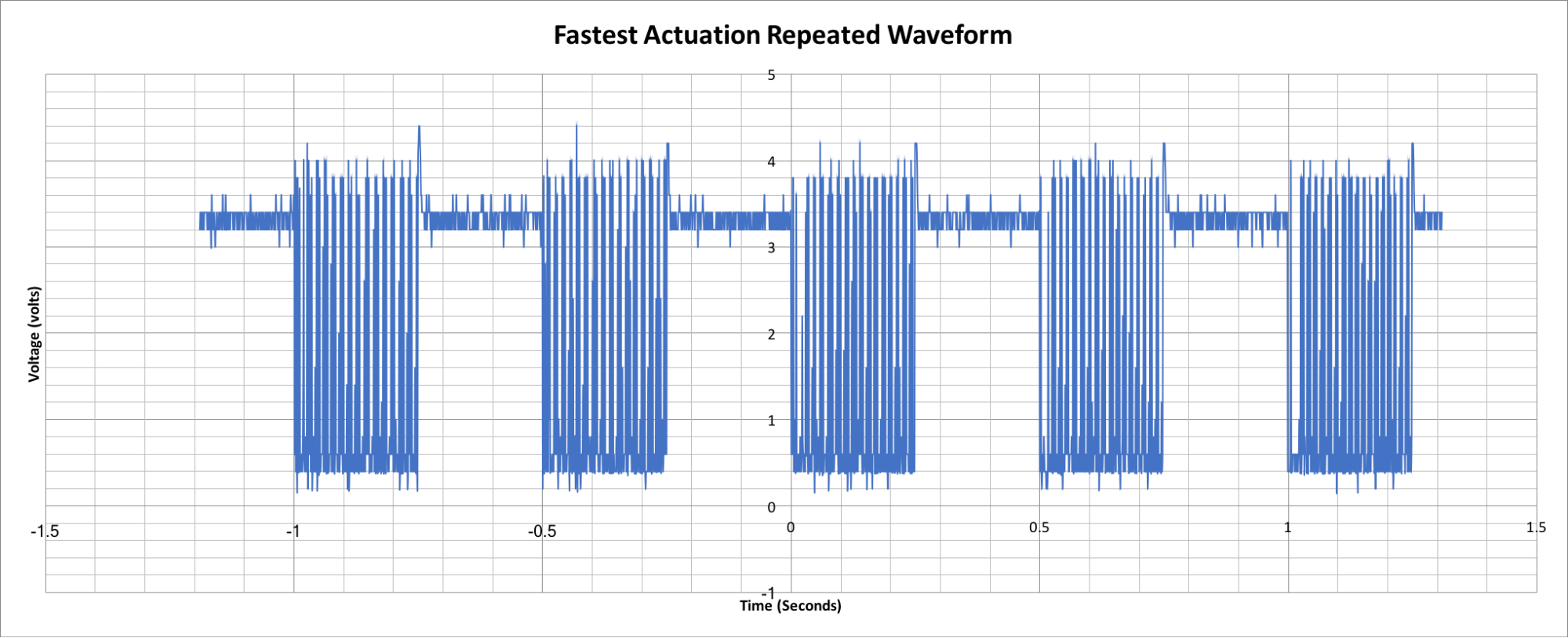
We set an upper limit to the reading rate of the device, since most visually impaired people can read at most up to 4Hz (characters per second). The following oscilloscope graphs show the voltage across a continuously actuated solenoid at this rate. While noisy, the correct period can be seen through the following two waveforms, along with the fact that the voltage oscillates more (due to ringing from the solenoid) when the solenoid is actually actuated.
Figure 25: Single Actuation of Solenoid
Figure 26: Repeated actuation of Solenoid
During the testing of the final product, we were able to gather two data points regarding the voltage level of the solenoid supply battery pack and the time between measurements. This could lend an indication as to the lifetime of the system, however, since we were only able to get two data points, and since battery voltage droop is a very non-linear and load dependent thing, we were not able to produce a graph of the phenomenon. However, the two data points are the following (Time, Voltage level): (0 min, 9.47V) and (16 min, 8.35V).
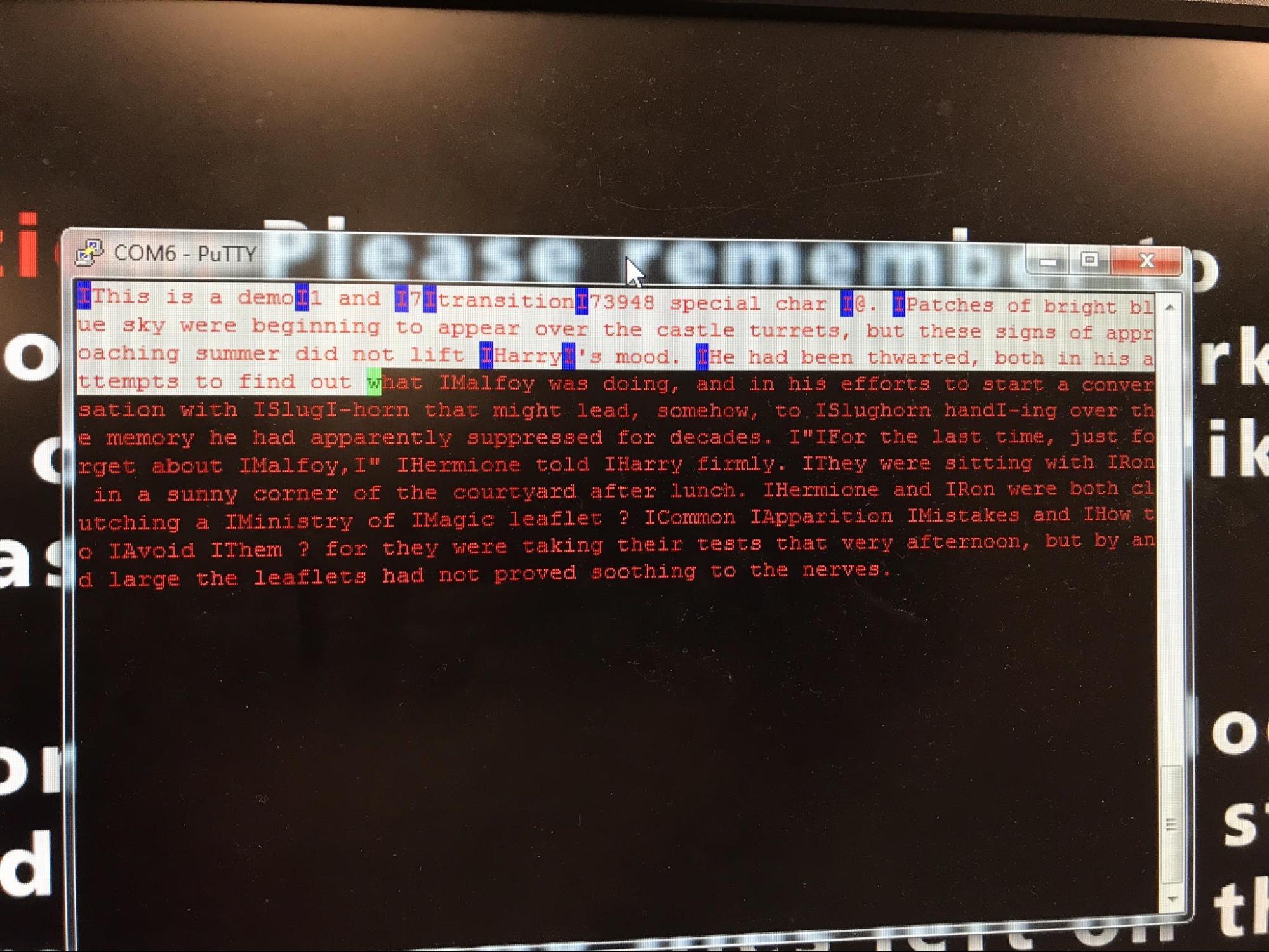
We were able to visually verify the accuracy of the debugger with the solenoid actuation by ensuring that the correct sequence was actuated when the same letter was highlighted in the debugger. For example, when a lowercase ‘a’ was highlighted in the debugger, the A labeled solenoid was the only one actuated.
The images below show the components of the project, in addition to the output of the debugger for a given sent character sequence.
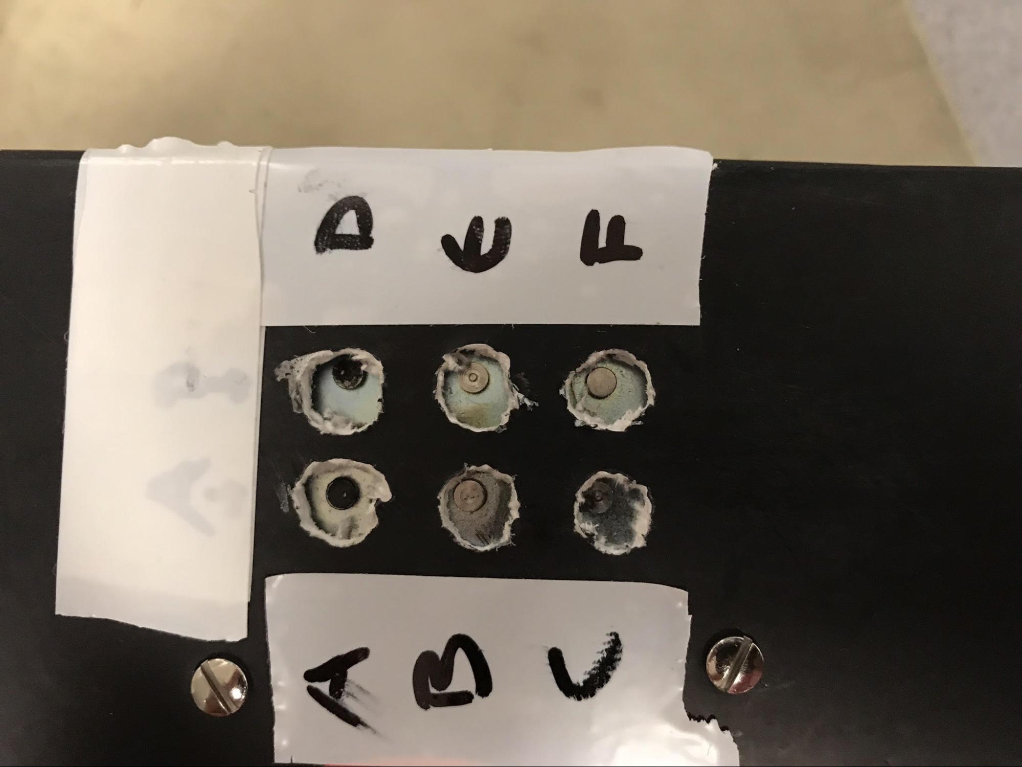
Figure 27: Mounted and Labeled Solenoids
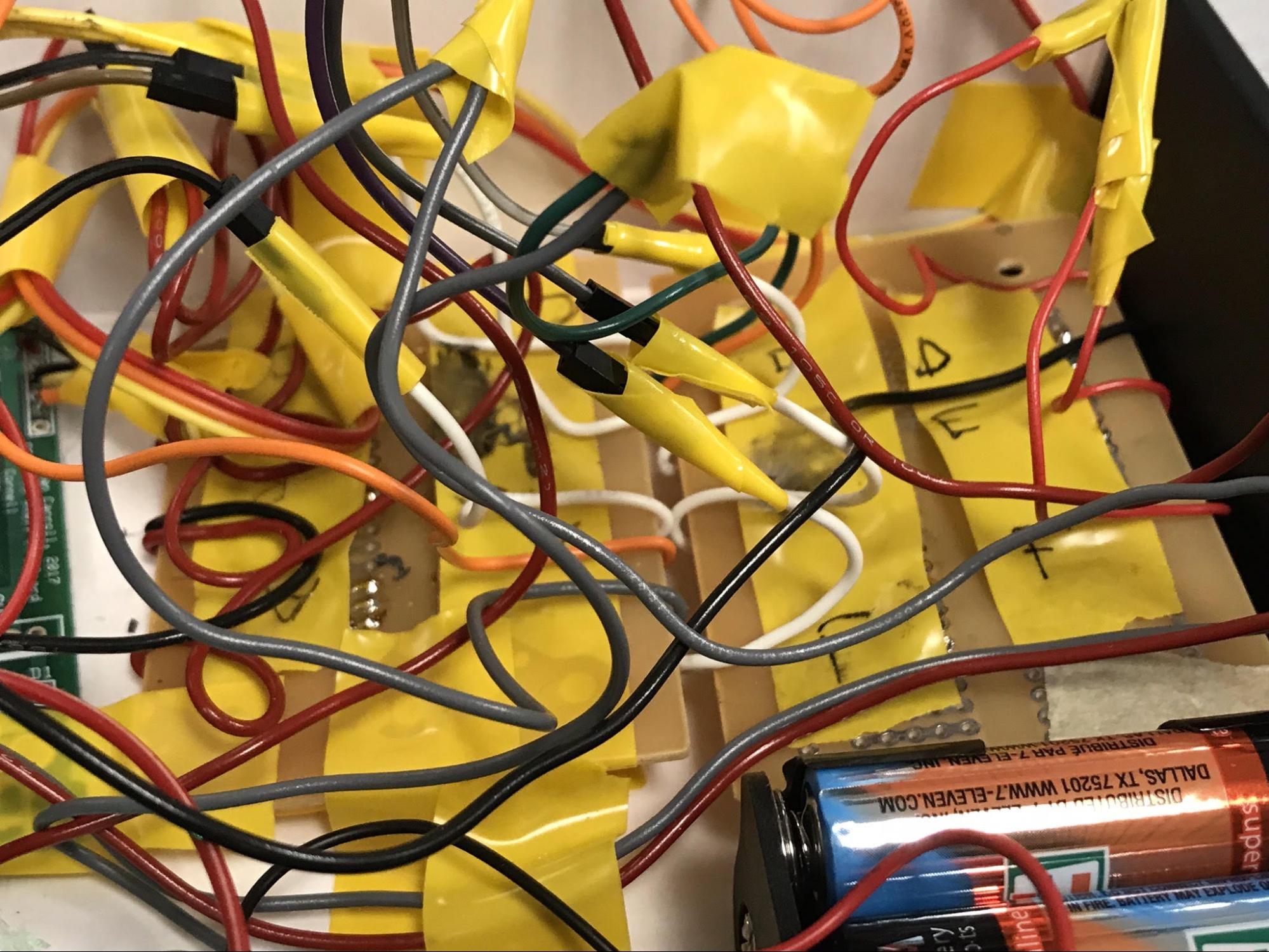
Figure 28: Taped Protoboards (in box)
Figure 29: PIC32 on Small Board
Figure 30: 3 DCDC Regulators
Figure 31: Debugger Output of Received File
The output of this project is documented and shown via the following youtube video, take by Bruce Land: Portable Braille Reader https://www.youtube.com/watch?v=N5iTWgvzhU8&index=16&list=PLKcjQ_UFkrd7JYi9yO2zcU4sMUj3x_pOL
CONLCUSION
Goals Accomplished
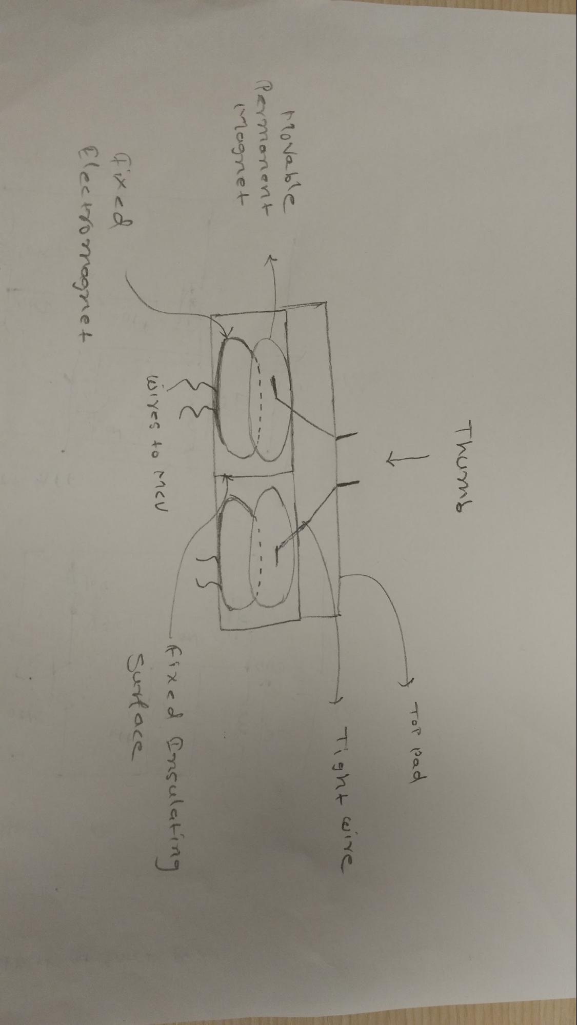
We started with the following rough initial design for our project.
Figure 32: Initial Design
During the first week of the project, we revised our design such as using solenoids instead of creating own temporary magnets, using putty terminal instead of TFT for the debugger and using UART for all peripherals instead of SPI.
Our initial proposed project timeline and actual weekly progress can be summarised in the table below.
Proposed Timeline | Actual Progress | |
Week 1 | Hardware Design (Electrical+Mechanical) and research on bluetooth, RF or Wifi | UART and escape sequence debugging |
Week 2 | Prototype hardware and progress on wireless protocol code | Basic code with ISR and single protoboard tested |
Week 3 | Improvements to hardware (Mainly mechanical design) and wireless protocol working with bluetooth phone application and checking the possibility of DMA (To get data from wireless device to flash) | Final code with unpackaged hardware successfully tested |
Week 4 | Final mapping of Braille characters and adjusting the refresh rate | Mostly packaging and wiring issues |
What Worked
We were successfully able to achieve all the design goals and functionalities that we initially proposed. We were able to legibly encode all the braille characters and display on the device with reasonable speeds which can be adjusted. The go-back functionality also worked as intended and was independent of the current reading speed or the character being read. The time and effort put in designing a debugger along the the main device was well justified as it not only helped us during the demo but it also helped us in verifying the various aspects of our design. The device dimensions were also reasonable considering the complexity of wiring and the fact that we did not use the custom board. Overall, we feel that we were able to live up to the name of our project and create a portable, easy to use and low cost braille reader.
What Did Not Work
Even Though our design is portable enough, we actually intended to make it much smaller than what we eventually had. Initially we planned on stacking protoboard and other components with layers of insulators between them and enclose everything in an aluminium casing. But not using a custom board and the use of solid core wires made it very difficult. After spending a long time on stacking the components, we finally decided to lay them flat in a sufficiently large box. But it helped us to explain the hardware better during the demo as it provided more visibility into the components.
We also wanted to have the spacing between the braille dots exactly similar to books or other devices. Placing six solenoids next to each other seemed good enough but not ideal. Therefore, we planned on soldering L-shaped hard wires on the solenoid plungers to bring all six contact points close to each other. But the soldering did not work as the plungers were made of steel. The second attempt was to use super glue which also did not work. Finally, we tried epoxy glue which seemed to be taking very long time to dry. Therefore, eventually we decided to use the solenoids directly for the contact points.
Learning Outcomes
The following summarizes the learning outcomes of this project and the class (ECE 4760) overall.
Building something from scratch
The entire process from concept/specifications to the final product was a great learning experience for us. It taught us how to use exiting understanding of concepts ex. SPI to implement similar but new concepts ex. UART. We also learned how the debugging process in hardware and software is very different and the only way to build a complex system is to use incremental design and teamwork with equal division of work.
Better technical writing
All the reports we wrote for ECE 4760 including the final project report has improved our technical writing skills. This is important as in some cases one needs to present a high level idea with product features like user guides or in some cases one needs to present detailed technical specifications like datasheets. This class will surely help us write even better technical reports in future.
Appreciation for Visually Impaired
During the process of this project we learned quite a lot about braille language and its accessibility to the users in various forms. We also gained appreciation for the specially abled people realising how hard it could be to learn braille and read it just by using finger tips without any visual stimulus.
Usability Considerations
As explained in the background math section, we thought carefully about the reading speed to make device usable in real world. With the use of bluetooth, features such as pause/restart, go-back, adjustable reading speeds and compliance to braille standard, the device can actually be used by any user to read, learn or teach braille. The current device dimensions and solenoid spacing do provide certain restrictions on the ease of use but this prototype can only get more user friendly with future improvements.
Future Improvements
Better Actuators
The possibilities include Piezoelectric vibrations at different frequencies or using Soft Actuators such the ones being developed by Prof. Kristin Peterson at CEI lab, Cornell University. The main advantage of using soft actuators is the reduction in power consumption, increasing the battery life and possibly also reducing the device size. The hardware complexity will depend on the specific driver circuitry for the specific actuator.
Memory
Assuming five characters per word, the PIC internal memory currently can store a single text file with approximately 2000 words. In order to support large books or multiple text files, we would like to add SD card to the device which can be interfaced with the microcontroller using a SPI channel. This will increase the cost by little but the enormous increase in the storage will be possible.
Dedicated App
The application will convert any file format to the simple text format. In case of multiple files, it can provide index reference with audio output for the user to select any file on the device to read in any order.
Support for Grade-II braille
For more advanced users, an optional support for Grade-II braille can be provided. As compared to the Grade-I brille, it has many contractions which increase the speed of reading and also reduce the memory requirement. For example, the most common words such as for, the, and, -ing, to etc. are encoded as a single instead of multiple braille characters.
Standards
The design level standards include adherence to the communication protocols such as UART and device logic levels for Bluetooth, FETs and Optoisolators. The application level standards include the adherence to various Braille standards. The encoding standard such as 1117B.5.6 was strictly followed while the physical standards such as 3.2.1 to 3.2.4 which govern the braille dot spacing, height etc. were not strictly followed.
Safety Considerations
The project does not pose any known threat to the safety of its users. All the internal circuitry has been properly insulated and solenoid toggling has been tested for the thermal worst case. During the development process, the ESD mats were mandatorily used. All the certified hardware components were used and purchased from the authorised vendors.
Intellectual Property Considerations
Our design, either hardware or software, was not directly inspired by any student projects or online microcontroller tutorials. The use of optoisolators in protection circuitry was inspired by the Lab 4 of ECE 4760. We are not aware of any known patents which are similar to our design. We used a header file provided by Prof. Bruce Land for the UART setup. The Protothreads we used is a free, open source library provided by the Adam Dunkels. The Peripheral library (PLIB) is provided by the Microchip.
Ethical Considerations
We did our best to follow the IEEE code of ethics. As for the ethical consequences of our device, we hope that it will have a positive impact on the lives of visually impaired people. Prior to starting our design we performed the diligent research to ensure we were not infringing on any copyrights of design or other existing patents. We designed the human interface to the project such that there would be no safety issues, including exposure to toxic substances. To the best of our knowledge, all presented data is accurate and reproducible, and reflects our honest work. We designed our project with the intention of aiding people with a perceived disability (visual impairment) and is not intended for the harm of any people. There was no bribery or other incentives provided to us in choosing this project, and does not violate the IEEE code of ethics.
Legal Considerations
All the references and standards have been clearly credited and stated. Therefore, we do not expect any legal consequences or restrictions. All the components including Bluetooth adhere to FCC standards and legal to use in US.
ACKNOWLEDGEMENTS
We would like to thank Prof. Bruce Land and all the TAs including Samir, Shaan, Mark, Brian G. and Brian C. for their advice and help throughout ECE 4760.
APPENDICES
Release Permission
The group approves this report for inclusion on the course website.
The group approves the video for inclusion on the course youtube channel.
Program Listing
Google Drive Code Link: https://drive.google.com/open?id=1F0SzYItFUm8jZ9AprBXnY3-OAYqALuJg
Schematic
Top Level Schematic:
Cost Details
Item Description | Link | Unit Cost ($) | Quantity | Total Parts Cost | Total Project Cost |
HC-05 Bluetooth Module | https://www.amazon.com/gp/product/B01G9KSAF6/ref=oh_aui_detailpage_o02_s00?ie=UTF8&psc=1 | 8.99 | 1 | 8.99 | 94.68 |
2x AA 9V Battery Pack Holders | https://www.amazon.com/gp/product/B019P0VDRO/ref=oh_aui_detailpage_o03_s00?ie=UTF8&psc=1 | 6.99 | 1 | 6.99 | |
Protoboard (Large) | N/A | 2.5 | 1 | 2.5 | |
BreadBoard | Rental | 6 | 1 | 6 | |
10 K Potentiometer | http://www.youdoitelectronics.com/philmore-10k-ohm-mini-potentiometer-pc74?fee=2&fep=2253 | 2.17 | 1 | 2.17 | |
ON-OFF Switch | http://www.youdoitelectronics.com/philmore-mini-on-off-toggle-spst-30-10007?fee=2&fep=926 | 2.19 | 2 | 4.38 | |
AA Batteries (6 pack) | N/A | 8 | 2 | 16 | |
LM2596 DCDC Boards | https://www.amazon.com/gp/product/B008BHAOQO/ref=oh_aui_detailpage_o04_s00?ie=UTF8&psc=1 | 4.3 | 3 | 12.9 | |
PIC32MX250F128B | 5 | 1 | 5 | ||
SOIC/SOT23 Carrier | N/A | 1 | 1 | 1 | |
Small Board | N/A | 4 | 1 | 4 | |
5V Small Push/Pull Solenoids | 4.95 | 5 | 24.75 |
Work Distribution
All project work was at high level divided simply in hardware and software design. Along with individual effort, we spent significant amount of time together in brainstorming ideas and debugging various issues.
Mihir | Ashish |
Lab Contribution :
| Lab Contribution :
|
Report Contribution :
| Report Contribution :
|
References
Literature Survey:
[2] http://www.braillebookstore.com/Harry-Potter-Books
[3] http://www.lssproducts.com/product/Perkins-SMART-Brailler/writing-and-labeling
[4] http://www.boundlessat.com/Blindness/Braille-Displays/Braille-EDGE-40
Code:
[5] UART setup in pt_cornell_1_2_2a.h by Prof. Bruce Land
[6] Protothread Library by Adam Dunkels
Datasheets:
[8] PIC32 Peripheral Libraries for C32 Compiler
[10] PPS Input table
[11] PPS Output Table
Vendors:
[12] Amazon
[13] Adafruit
Contact Information
Ashish Shinde : ahs278@cornell.edu
Mihir Marathe : mmm389@cornell.edu
For references, Please contact Prof. Bruce Land : bruce.land@cornell.edu