IoT Hand Gesture Video Control
Peidong Qi - pq32@cornell.edu
Weiyou Dai - wd248@cornell.edu
Introduction
In this project, we designed and implemented a system that will utilize light & shadow and relative distance to to recognize the single hand gesture in the air and use different gestures as commands like volume up or speed up to control a video playing. While using keyboard keys to control videos can sometimes be tedious, we want to use hand gesture in the air, which is more intuitive and simple. We used distance sensors to collect distance data and multiple phototransistors to collect shape and area of the hand and compare against certain template to determine the final command. The command will be sent to a PC via UART/Serial wire to control the video.
High Level Design
Rationale
As the Internet of Things(IoT) and smart home concepts have an increasing trend in the general public, it could have a broad application if people can control home appliances with hand gestures. In this project, a hand gesture capture controller device will be developed. The device can used to control the Youtube video player on the computers with the user's simple hand gesture. For example, there will be nine controlling gestures in this project, which are for: pause/unpause, fast forward, fast backward, speed up, slow down, volume up, volume down, mute/unmute and fullscreen. If a user holds a fist, then the video will be full screen; if a user moves the hand towards the side direction(default set by developers), then the video will go fast forward or rewind 5 seconds; if a user raises the hand up, then the volume will go up; if a user puts the hand down, then the volume will go down; if a user hold a palm, then the video will be paused.
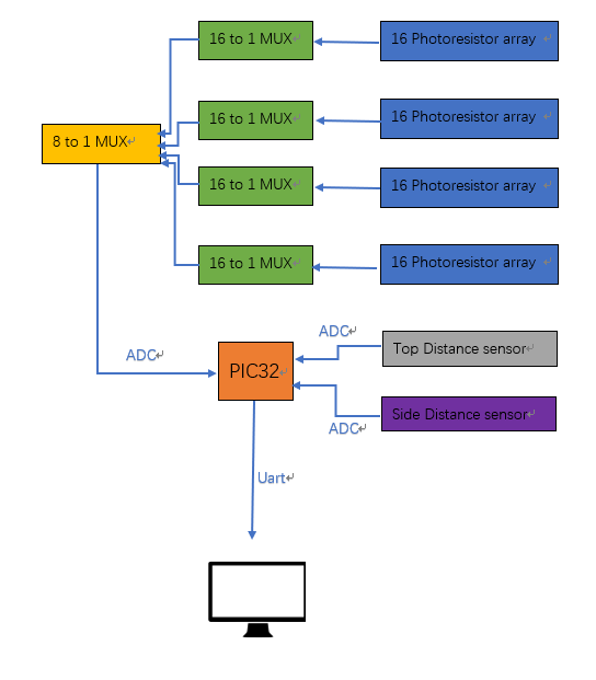
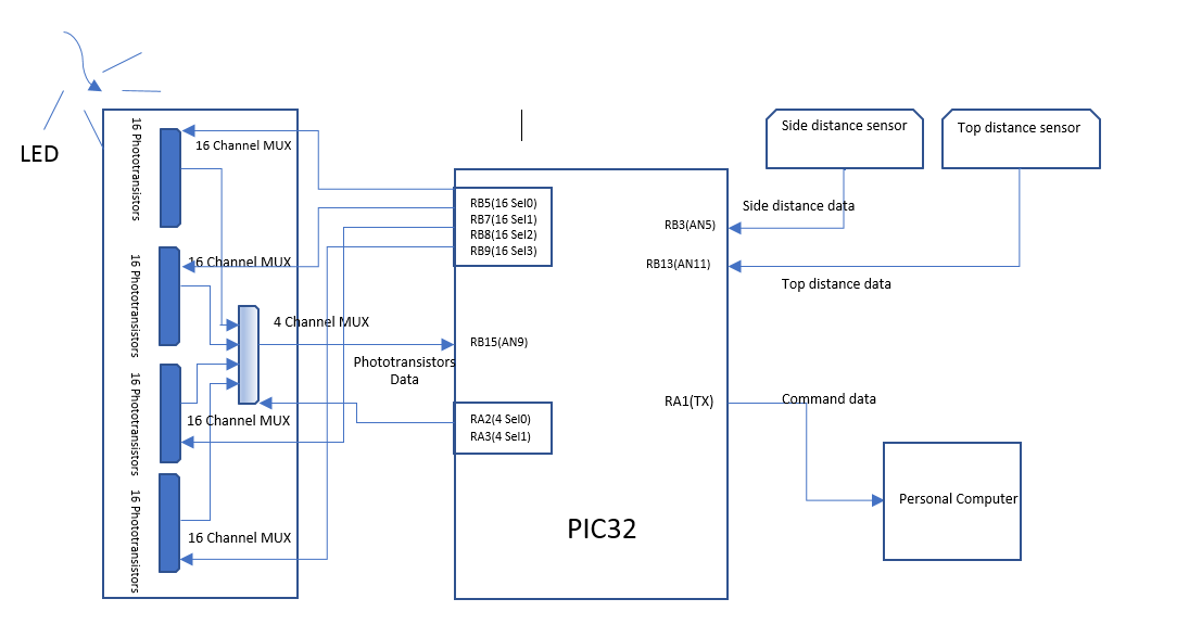
The plan as it currently stands will involve two main parts, sensing & recognition parts and controlling parts. For the sensing parts, a combination of phototransistors and distance sensors will be used. We will put the sensors set in a black paper box and have one LED lights on the top of the box. There will be 64 phototransistors(8x8) putting on the bottom of the box to take a measurement of shadow created. Therefore, by taking the shadow from the bottom, a rough hand gesture can be captured. In order to have a more accurate measurement of the relative hand position, 2 distance sensors will be placed on the top and left sides of the box to take a distance of the hand relative to the both sides for fast forward, fast backward, volume up and volume down gestures. For the controlling part, ADC will be used for converting the analog measurements of phototransistor and distance sensors to digital values. Multiplexers will then be deployed to take digital photo-sensors values and send the values for further determination to the main processor PIC32. PIC32 will distinguish and determine which hand gesture is displayed based on the data combination of Multiplexers and distances sensors. Then the processed output data will be transfer from PIC32 to a computer via a USB 2.0 cable. When the video is played, it will have different actions depending on the hand gestures. The hand gesture capture and data processing & transportation should be synchronous. There will be a PCB board to reduce the amount of wires and size of the entire board with the PIC32. With the advent of IoT era, an increasing number of people tent to control home appliances intuitively and easily. With the application of this project, people do not have to stand up and move to the table to use the mouse and control the video playing on the computer. Instead, they could just sit on the cozy sofa and use hand gesture.
Logical Structure
Overview of System Design
hardware/software trade offs
For our project, we have used 64 phototransistors for shadow area detection. 64 phototransistors can form an 8 by 8 matrix in one feet by one feet area. As we can know, the accuracy will increase with the increment of amount of the phototransistors in certain area. However, the time delay will increase. So there is a trade off. We need a fine resolution and also a fine time delay. So we choose 64 phototransistors.
IEEE, ISO, ANSI, DIN, and Other Standards
- USB 2.0 standards: We intend to connect our system to a computer via a usb 2.0 cable.
- IEEE Risk management: We take safety consideration at a high priority and think about the risk/safety for development workspace and home/office.
- IEEE 1016 Software Design Description: We discussed the firmware from the Logical, Dependency, Structure, Algorithm, and state dynamics viewpoints
Software
ADC setup
To read from multiple sensors, we set up three ADC ports which are AN5(RB3), AN9(RB15), AN11(RB13). In the setup code for ADC in the main method, the ADC scan mode has been turned on, and the ADC sample number per interrupt has been updated to 3. While ADC is scanning through all the ADC ports, we did not want to skip AN5, AN9, and AN11. Therefore, in the PARAM5, we did not include SKIP_SCAN_AN5, SKIP_SCAN_AN9, SKIP_SCAN_AN11. In the SetChanADC10() API, we only needed ADC_CH0_NEG_SAMPLEA_NVREF as a parameter. The setup code details are listed as below:
CloseADC10();
#define PARAM1  ADC_FORMAT_INTG16 | ADC_CLK_AUTO | ADC_AUTO_SAMPLING_ON
#define PARAM2  ADC_VREF_AVDD_AVSS | ADC_OFFSET_CAL_DISABLE | ADC_SCAN_ON | ADC_SAMPLES_PER_INT_3 | ADC_ALT_BUF_OFF | ADC_ALT_INPUT_OFF
#define PARAM3 ADC_CONV_CLK_PB | ADC_SAMPLE_TIME_15 | ADC_CONV_CLK_Tcy
#define PARAM4 ENABLE_AN9_ANA | ENABLE_AN5_ANA | ENABLE_AN11_ANA
#define PARAM5 SKIP_SCAN_AN0 | SKIP_SCAN_AN1 | SKIP_SCAN_AN2 | SKIP_SCAN_AN3 | SKIP_SCAN_AN4 | SKIP_SCAN_AN6 | SKIP_SCAN_AN7 | SKIP_SCAN_AN8 | SKIP_SCAN_AN10  | SKIP_SCAN_AN12 | SKIP_SCAN_AN13 | SKIP_SCAN_AN14 | SKIP_SCAN_AN15
SetChanADC10( ADC_CH0_NEG_SAMPLEA_NVREF);
OpenADC10( PARAM1, PARAM2, PARAM3, PARAM4, PARAM5 );
EnableADC10();
Read distance
We deployed two Infrared distance sensors to read the hand distance for recognizing hand gestures. There is one on the top of the box, and the other one on the left side of the box. We used a distance sensor whose range is from 4 cm to 30 cm and it is within our measurement range. They are both powered by the PIC32 big board. The readings from top distance sensor is purely for two commands: Volume up and volume down. The readings from side distance sensor is purely for another two commands: move forward and move backward. To get the most accurate readings from two sensors, rather than using a 2 in 1 multiplexer and reading one by one, we instead setup two ADC ports AN5(RB3) and AN11(RB13) on the PIC32 big board and read directly from the two sensors. Because there are interference between the top distance sensor and the side distance sensor when the hand is between both of them, we will need to avoid the noise as much as possible. To avoid the interference, two integer global arrays with a size of 10 have been created. The arrays will be filled with readings from ADCs in a for-loop and can be shared throughout the entire file. By setting up a tolerance value, for example 3, we are able to discard unexpected noise and get the accurate results for recognition. Additionally, the two sensors’ readings are printed on the TFT display for debugging purpose.
Multiplexers(MUX)
In this project, because we did not have enough ADC ports to read from 64 phototransistors, we used 5 multiplexers to read the values from 64 phototransistors. 4 16-channel MUXs have been used to read the phototransistors directly and they are selected by 4 output pins from PIC32 big board. Then the 4 output will be selected by another 4-channel MUX for 1 output. As we did not have a 4-channel MUX handy, instead we used a 8-channel MUX and grounded “select2” pin. The table below listed the pins used for MUX data selection.
| PINs on PIC32 big board | MUX connection | Note |
|---|---|---|
| RB5 | 16-channel MUX select 0 | Output from PIC32 |
| RB7 | 16-channel MUX select 1 | Output from PIC32 |
| RB8 | 16-channel MUX select 2 | Output from PIC32 |
| RB9 | 16-channel MUX select 3 | Output from PIC32 |
| RA2 | 8-channel MUX select 0 | Output from PIC32 |
| RA3 | 8-channel MUX select 1 | Output from PIC32 |
| Ground | 8-channel MUX select 2 | Unnecessary |
Layout and assigned Pins for MUX
By clearing and set bits in associating ports before ReadADC10() API, we are able to obtain each phototransistor reading. One thing to note is that we need to wait for 1 mill-second before reading ADC value. Otherwise it will cause data reading shift because without waiting, there is not enough time to update ports and bits information for ADC
       mPORTBClearBits(BIT_5 | BIT_7 | BIT_8 | BIT_9);
       mPORTAClearBits(BIT_2 | BIT_3);
       mPORTASetBits(BIT_2 | BIT_3);
       mPORTBSetBits(BIT_8 | BIT_9);
       PT_YIELD_TIME_msec(1);
       valueFromADC = ReadADC10(1);
Read phototransistor
In addition to the distance sensors, we also read from 64 phototransistors for raw light and shadow values. We intended to use template to match the shadow created by hand and give out commands to control the video playing. Since it is a large amount of readings and it is impossible to read 64 values all at the same time with available ADC ports, we used multiplexers(MUX) to achieve that. We have 4 16-channel MUX to take all the readings from 64 phototransistors and then we passed all 4 outputs to a 4-channel MUX for 1 final output. We provided AN9(RB15) with the final output and got the value. To read from a single phototransistor, we need a pull-down resistor. After measuring the resistance of phototransistor in a dark and bright space, we chose 5.1k Ohm resistor as the “pull-down” resistor as it gives us an optimal reading from phototransistor. We connected each phototransistor with the circuit below and read the Vo values. Thus, the phototransistor reading will decrease when there is shadow on the phototransistor, which is intuitive to us.
To process 64 phototransistors’ values, we created an 8x8 matrices to take in all values and scan through all of them. To convert that in C program language, we built a global 2D integer array with a size of 8 by 8 and scan through the array with a nested for-loop. After reading from ADC, the value will be multiplied by 10 because the raw value was too small to be distinguished for different gestures. Then the multiplied value will be put into the assigned location in the 2D array for further recognition. We assigned the values in the array based on their absolute location on the hardware layout. For example, for the phototransistor on the left up corner, its location will be photoTransistorReading[0][0] where photoTransistorReading is the global 2D array defined above. A switch machine has been used to read 64 phototransistors. There is a temporary integer value called channel64MuxSelect which serves as an index and keeps track of the state to enter. The channel64MuxSelect will be incremented by 1 at the end of each state and will lead the program to go the next state. At the end of the state machine, the value will be reset to 0 to re-enter the state machine. For debugging purpose, the 8x8 array is printed on the TFT and will be updated with real-time readings from 64 phototransistors. Reading phototransistors is in a separate thread because we want to keep one thread with one functionality and independent from distance sensors readings. A code sample for reading phototransistors and printed on TFT looks like below:
      case 63:
                mPORTBClearBits(BIT_5 | BIT_7 | BIT_8 | BIT_9);
                mPORTAClearBits(BIT_2 | BIT_3);
                mPORTASetBits(BIT_2 | BIT_3);
                mPORTBSetBits(BIT_8 | BIT_9);

            	PT_YIELD_TIME_msec(1);
            	valueFromADC = ReadADC10(1);
            	tft_fillRoundRect(start_x_tft+7*horizontal_gap_tft-1, start_y_tft+7*vertical_gap_tft+ print_number_offset_tft, 25, 10, 1, ILI9340_BLACK);// x,y,w,h,radius,color
                if (valueFromADC*10 < display_threshold) {
                    tft_setCursor(start_x_tft+7*horizontal_gap_tft, start_y_tft+7*vertical_gap_tft+ print_number_offset_tft);
                    tft_setTextColor(ILI9340_YELLOW);
                    tft_setTextSize(1);
                    sprintf(buffer,"%d", valueFromADC*10);
                    tft_writeString(buffer);
                }
            	photoTransistorReading[7][7] = valueFromADC*10;
            	valueFromADC = 0;
            	channel64MuxSelect_Up_Left = 0;
            	break;
Recognition
Though able to read the distance sensors and phototransistors and stored values in desired data structures, we need to recognize the hand gestures and give out commands to the video playing. For each command, their associated recognition are introduced. For pausing/resuming a video on Youtube, a user will need to hold a palm above the phototransistors at the bottom of the box. In the while loop of the recognition thread, we scanned through the 2D array with a nested for loop. It goes from left side to right side and from up to down side of the array.
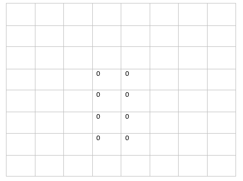
We created a special template for palm and once the template is matched, it will send out the command to UART serial for data transfer to a PC and print the command on the TFT for visibility. The template for pause/resume is two adjacent columns of 4 phototransistors. When the hand is covering those 8 phototransistors, the readings from the phototransistors will decrease to below the our threshold, which is 100. Then our system will recognize this gesture as a palm and will set a global character variable “cmd” to ‘p’. Then ‘cmd’ will be transfer to a PC by UART serial connection in another thread introduced below in section 3.1.5. One thing to note is that while there is ‘p’ command and the hand is still holding a palm, we do not want to send another ‘p’ command again to resume the video but hold ‘p’ command until next different command coming up. We did that by having a temporary character variable called “lastCommand”. If the “lastCommand” and current “cmd” can match, then we do nothing; if they are different, then we will update “lastCommand” with the current “cmd” value.
Template for pawn
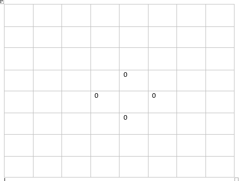
For muting/unmuting the video, we used a circle as the template. When a user holds a circle with a single hand which created a hole at the center. Therefore, when there is light on the center phototransistor but there is little light at the adjacent four phototransistors in the left, right, up, and down positions, the system will recognize it as a circle and will send out a command ‘o’ to the PC via UART/Serial. Again, it will print the command as “Mute/UnMute” on the TFT for debugging purpose.
Template for mute
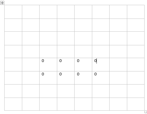
Furthermore, we used a fist template for enabling/exiting full-screen mode. When there are shadows on the center two phototransistors on the first row, four middle phototransistors vertical down on the second row, and two center phototransistors vertical down on the third row and the readings are all below the threshold, which is 200 in this case, the system will recognize the gesture as a fist and will send out a command as ‘f’ to a connected PC via UART/Serial. All the hand gestures recognition mentioned above can be applied anywhere at the bottom of the box where 64 phototransistors are laid out. There are some edge-case where some hand gestures recognition can be false-negative. For example, when a hand is high enough in the box and covers most of light at the bottom, then the templates for both “fist” and “palm” will match. We bypassed that by setting the hand gesture level to be right above the phototransistors. In addition, we used a if-else statement to distinguish the two gestures. If first the “palm” gesture does not get matched, then we check if the “fist” gesture can be matched. By applying all these optimization, we improved recognition rate by 20% from 65%.
Template for fist
For speeding up and slowing down a video, we used two fixed locations on the bottom of the box. When there are shadows on the four phototransistors in a square shape at the left down corner and there are light at two phototransistors above and right hand of the square, a ‘q’ command will be send out to the PC via UART/Serial which will result in slowing down the video. On the other hand, when there are shadows on the four phototransistors in a square shape at the right down corner and there are light at two phototransistors above and left hand of the square, a ‘e’ command will be send out to the PC via UART/Serial which will result in speeding up the video.


Template for speed down and speed up
For the four commands: fast forward, fast backward, volume up, volume down, we used distance sensors solely for recognition as it gives us the most accurate results. Top distance sensor readings are used for volume up and volume down and side distance sensor readings are used for moving forward and moving backforward. As we have the readings arrays for two distance sensors topDistanceList and sideDistanceList, we first iterate through the array and then check the values in the arrays. We stored previous reading values by keeping four temporary integer variables called lastFromTopDistance_down, lastFromTopDistance_up, lastFromSideDistance_right, lastFromSideDistance_left. We are also keeping another four temporary integer variables called wrong_right_count, wrong_left_count, wrong_up_count, and wrong_down_count.
For moving forward command, while we are iterating through the sideDistanceList, if the lastFromSideDistance_right is less than the next indexed element in the sideDistanceList array, then we determine it is a wrong reading and increment wrong_right_count. After iteration, if the wrong_right_count is less than or equal to the tolerance value which is set to 3 in this project, we still regard this event as a “move forward” command and give out the cmd as ‘r’. If the wrong_right_count is greater the tolerance value, we did not recognize the hand gesture.
On the other hand, for moving backward command, while we are iterating through the sideDistanceList, if the lastFromSideDistance_left is greater than the next indexed element in the sideDistanceList array for more than three times, then the system will not recognize the hand gesture. The system will only determine it is a “Move backward” command and give out cmd as ‘l’ if the wrong count is less than or equal to 3
For volume up command, while we are iterating through the topDistanceList, if the lastFromTopDistance_up is greater than the next indexed element in the topDistanceList array, then it is a wrong reading and system will increment wrong_up_count. After iteration, if the wrong_up_count is less than or equal to 3, we regard this event as a “volume up” command and give out the cmd as ‘u’. If the wrong_down_count is greater than the tolerance value, we did not recognize the hand gesture.
On the other hand, for “volume down” command, if the lastFromTopDistance_down is less than the next indexed element in the topDistanceList array for more than three times, then the system will not recognize the hand gesture. The system will only determine it is a Volume down” command and give out cmd as ‘d’ if the wrong count is less than or equal to 3.
UART & Serial
For this project, we used Uart serial port to transfer data from PIC32 to PC. There are three communication methods: Uart, SPI, I2C. Our initial design was to use I2C to make the communication. The advantage of I2C is we can use more than one master in the electronic circuit design. In our design, we only need one master device and one slave device. And I2C need more complicated hardware design. After doing some research on I2C, we decided not to use it. Then we have moved on SPI. The advantage of SPI is the transfer rate is fast. SPI has the fastest transfer rate in those three communication methods. However, the SPI requires the most complicated hardware connection. It required four pins. And software set up is complicated. Then we only need to transfer a string from PIC32 to PC, we decided to use Uart. The advantage of Uart is easy to set up. The hardware setup is less complected. Since we only need two devices to communicate. Without considering the transfer rate, the Uart is the best communication method for our project.
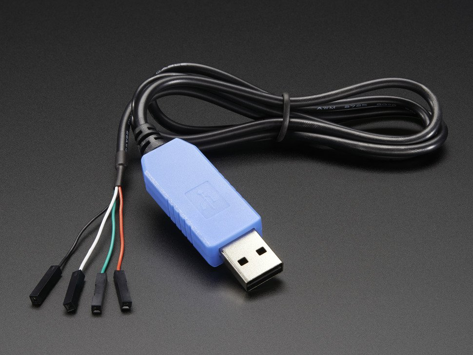
In order to use Uart, we need to implay protothread 1_2_2 instead of protothread 1_2_1. And the BAUD rate is already set up in config_1_2_2.h. We also need to set up the serial port in PC end. On the PC, we have created a java program that can read the serial data. In the java program, we set the serial port to be 9600 baud, no parity, 1 stop-bit and no flow-control. To connect PC and PIC32, we used uart to usb adafruit serial cable. Since we only need to read the serial data from PIC32, we only connect uart receive pin to the green wire and ground pin to black wire.
Once the PC end receive the serial data, the program will put the data into a string. After we studied Youtube video player, we found out the we can use the keyboard to do the video control. For example, the space key can pause the video ane “M” key can mute the video. So we figured out that we can use java program to control the keyboard to do the video control. All we need to do is map the different string to different keys. To control the keyboard, we used java’s robot AWT class. This allowed us to use the simulate the key press and release.
| Action | Shortcut |
|---|---|
| Toggle play/pause the video | k or Spacebar |
| Go back 5 seconds | Left arrow |
| Go back 10 seconds | j |
| Go forward 5 seconds | Right arrow |
| Go forward 10 seconds | l |
| Skip to a particular section of the video (e.g., 5 goes to the video midpoint) | Numbers 1-9 (not the keypad numbers) |
| Restart video | 0 (not the keypad number) |
| Go to Full Screen mode | f |
| Exit Full Screen mode | Escape |
| Go to beginning of video | Home |
| Go to end of video | End |
| Increase volume 5% | Up arrow |
| Decrease volume 5% | Down arrow |
| Increase speed | Shift+> |
| Decrease speed | Shift+< |
| Move forward 1 frame when video is paused | . (period) |
| Move backward 1 frame when video is paused | , (comma) |
| Mute/unmute video | c |
| Cycle through options for caption background color | b |
| Move to the previous video in a playlist | Shift+p |
Here is the list of all the shortcut in the youtube keyboard video control. We decided to use pause, go back 5 seconds, go forward 5 seconds, go to fullscreen mode, increase volume, decrease volume, increase speed, decrease speed and mute/unmute video action. That means we need to simulate “space”, “f”, “left arrow”, “right arrow”, “up arrow”, “down arrow”, “shift + >” “shirt + <”, “m”. We mapped nine different strings to those keys
| Command | Shortcut key |
|---|---|
| “U” | up arrow key |
| “D” | down arrow key |
| “L” | left arrow key |
| “R” | right arrow key |
| “P” | space key |
| “F” | f key |
| “O” | m key |
| “Q” | shift +> |
| “E” | shift+< |
Hardware
Phototransistor
Because we are using 64 phototransistors and 4 16-channel multiplexers, we put 16 phototransistors on 1 Prototype PCB and connected their outputs onto another 8-channel multiplexers. Then we will use the output from 8-channel MUX as our reading. We set up firmware to iterate through all 64 of them. On each Prototype PCB, each phototransistor is connected to a 5.1k Ohm resistors. All of their outputs are connected to the input line of the 16-channel multiplexer. One of the final prototype PCBs layout are as below:
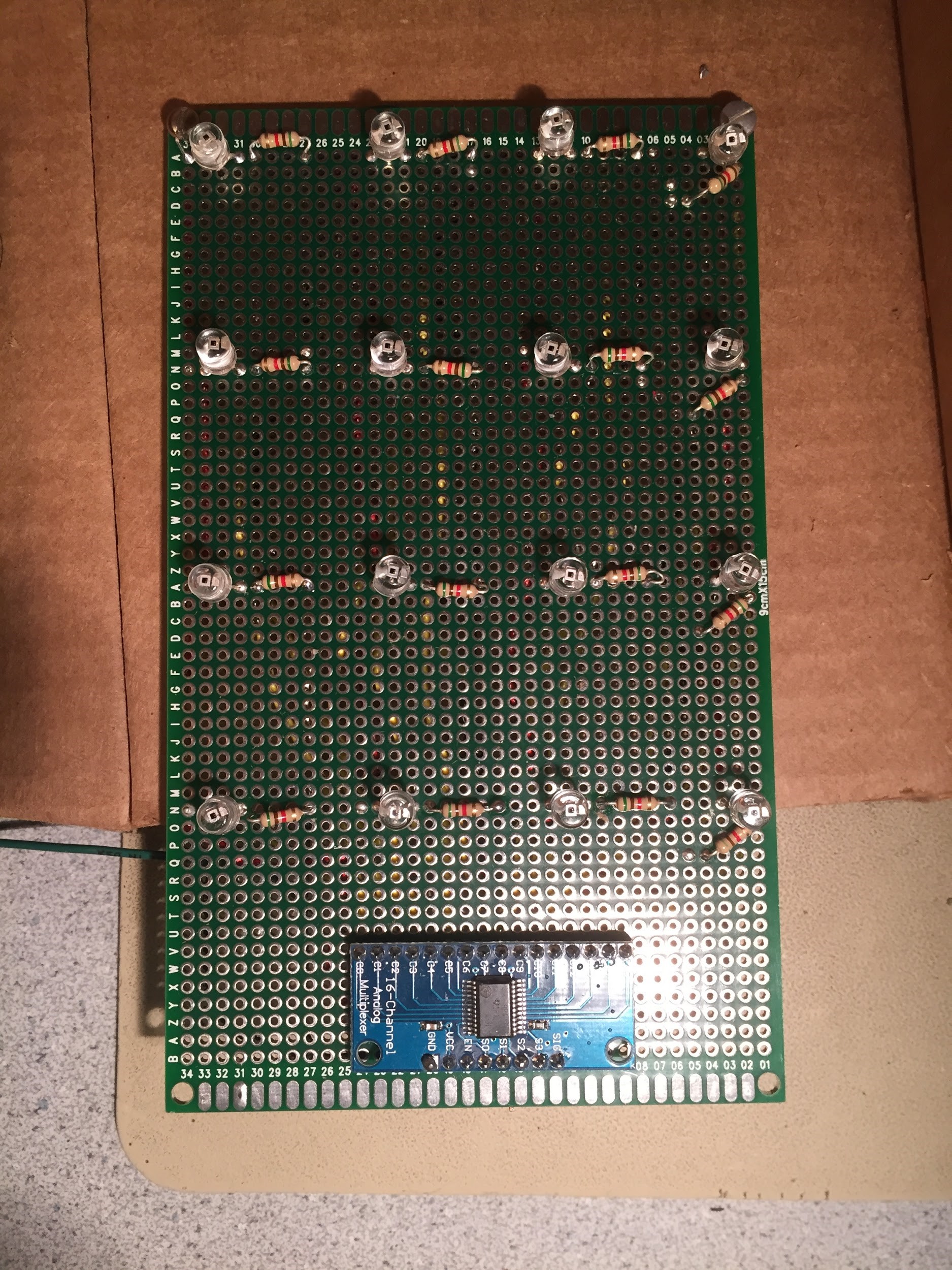
Layout of one Prototype PCB with 16 phototransistors, 16 5.1kOhm resistors, and a 16-channel MUX
Before the final layout, we had two prototypes for testing purpose and optimized our system step by step. Initially, we just wanted to ensure that our ideas of using phototransistors can work. Therefore, we implemented an 8-phototransistor system like the one below(Phototransistors have been removed.). The labels on the breadboard indicate their input index on the MUX.
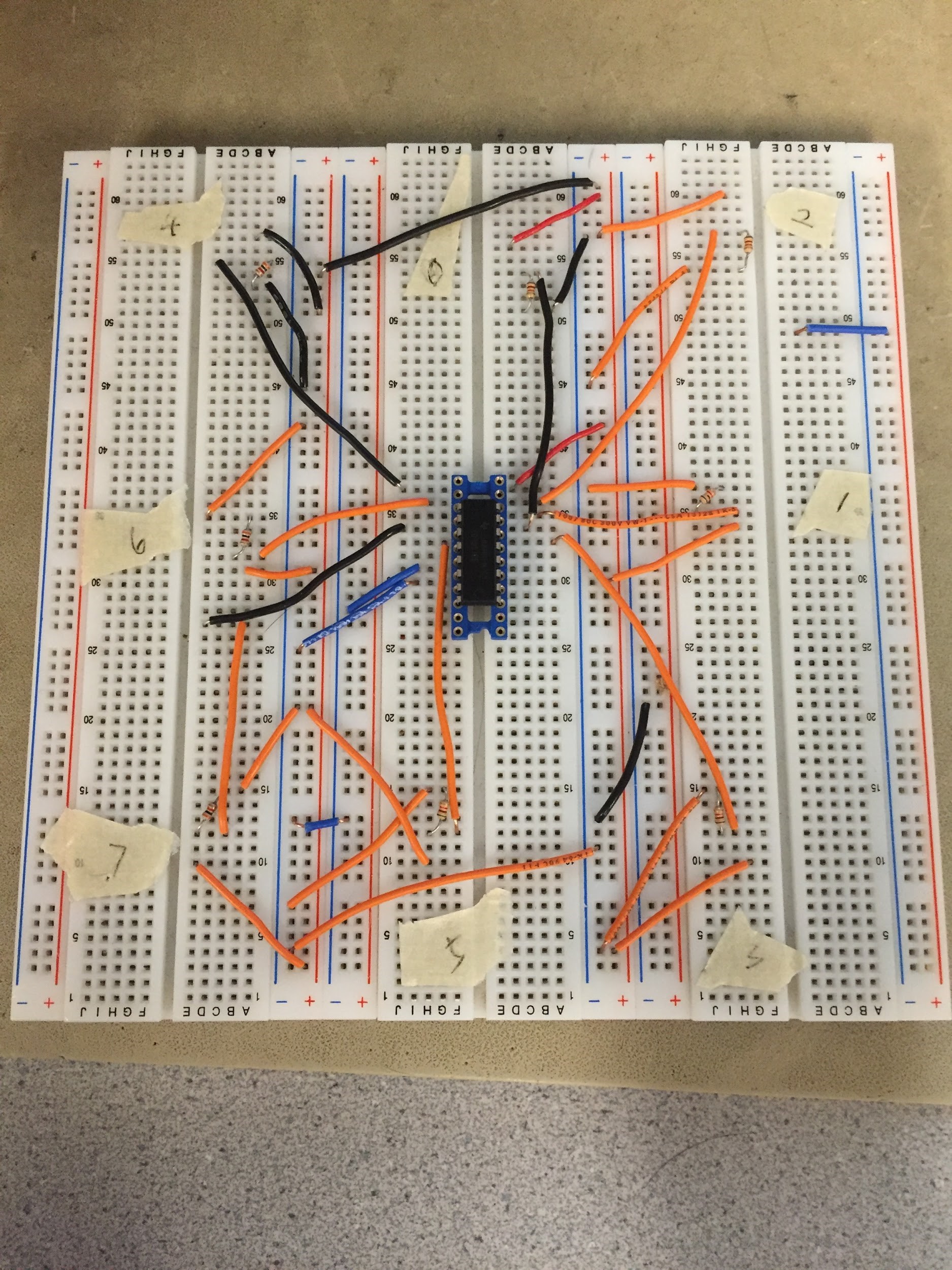
Layout of a 8-phototransistor system(phototransistors have been removed)
After making sure the 8-phototransistor system worked fine, we moved on to the next step and implemented a system with 16 phototransistors. In this test run, we want to make sure the 16-channel MUX can work properly and whether there is an inconspicuous time delay. The layout of 16 phototransistors are as below(phototransistors have been removed).
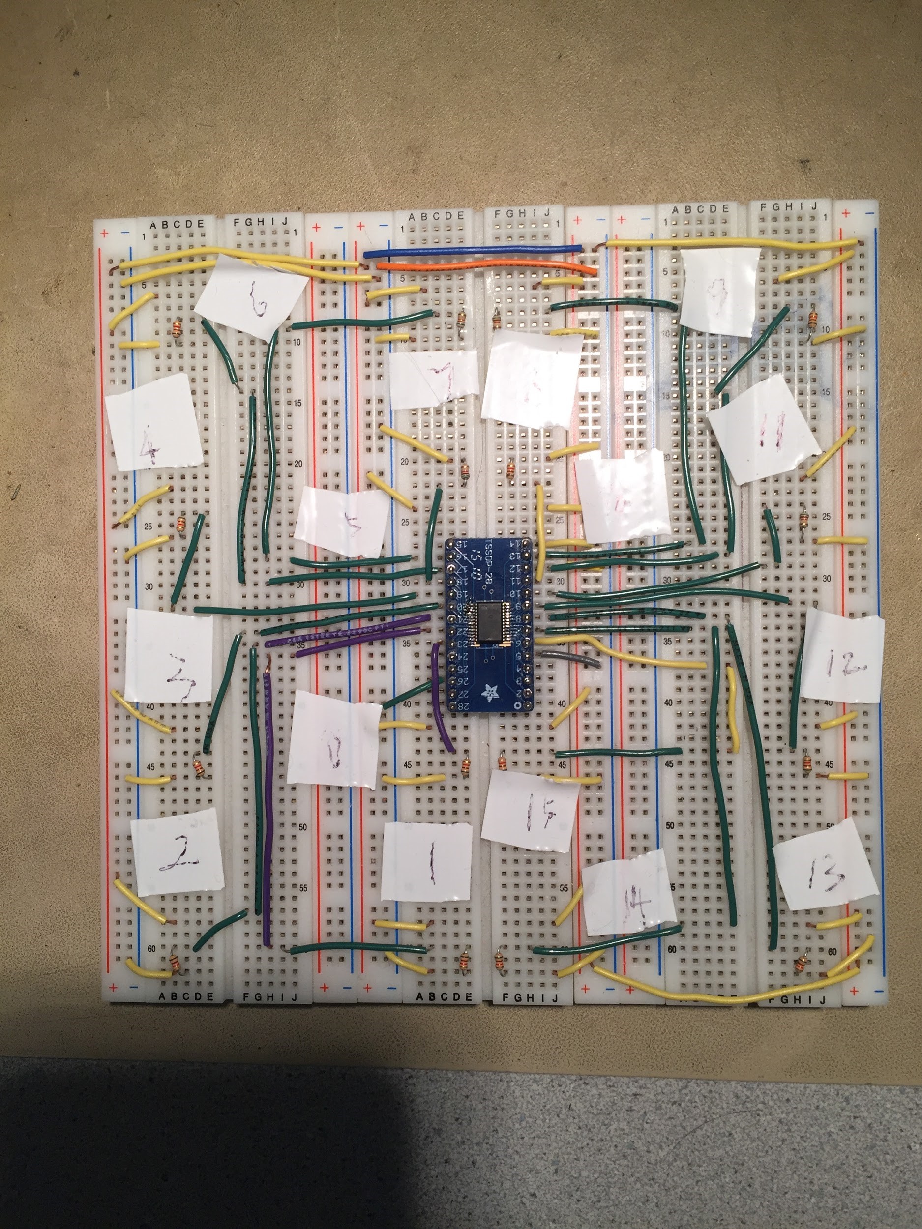
Layout of a 16-phototransistor system
When we were convinced that our 64 phototransistors could work properly after seeing a working 16 phototransistors prototype, we started to finalize our design and implement the final system. We decided to use Prototype PCBs because it gives users a clean visual and is easy to place in the box. We soldered all the wires on the back of the PCB boards so that it is clear and simple for recognition. In addition, we put all the wires together so that it is easy to debug the system. The final layout of the phototransistors system are below. From the top, 64 phototransistors form a square shape matrix and give us the most accurate result.

Layout of a 64-phototransistor system
All the wires are connected breathe the box or on the one side of the box. The connection of wires is shown in the picture below.
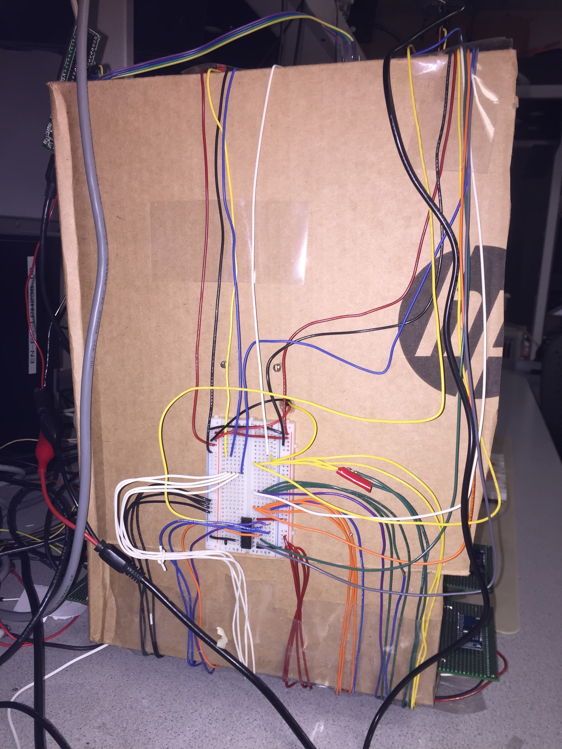

Layout of all the wire connection
Entire system
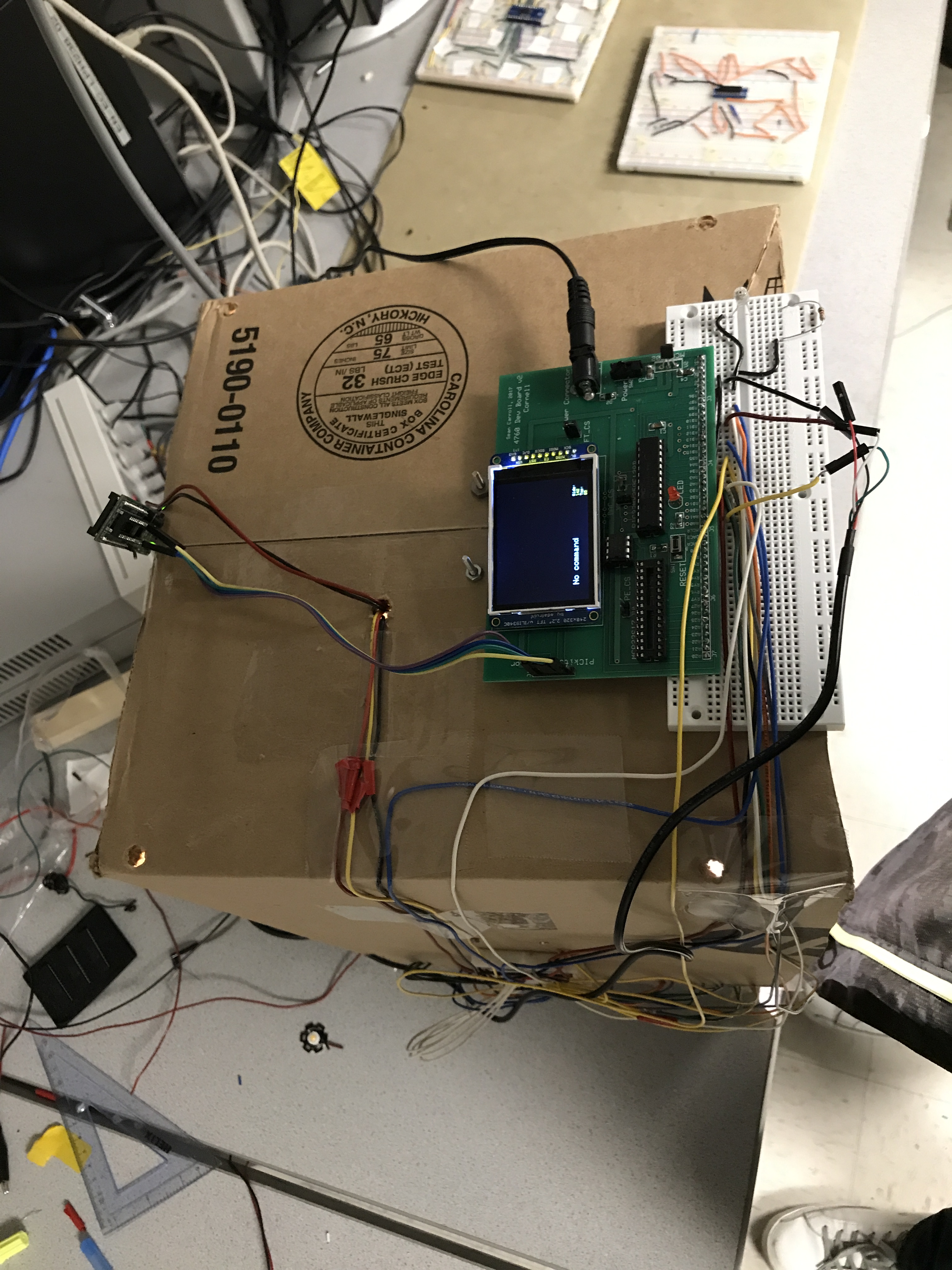
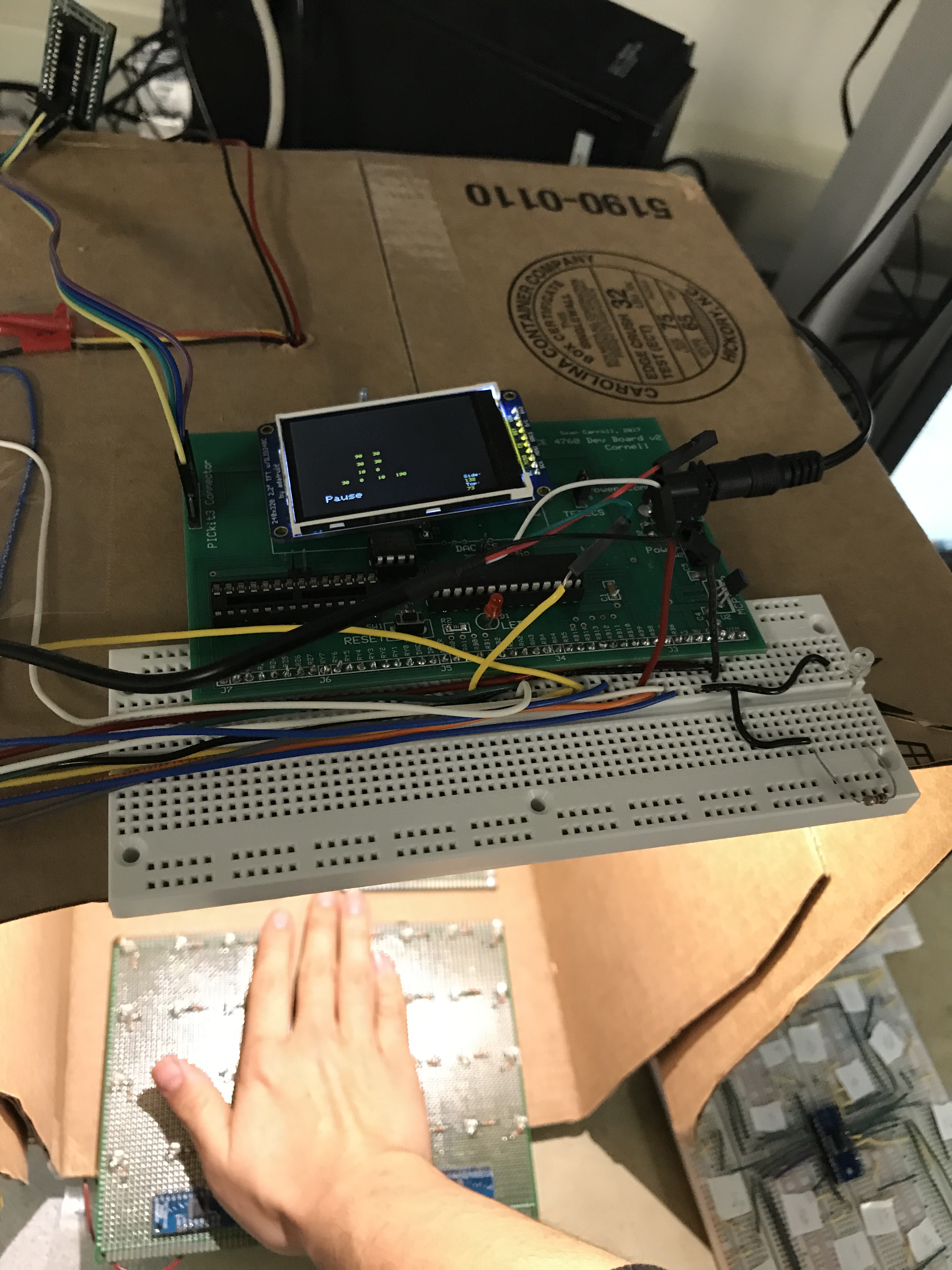
After connecting our distance sensors, phototransistors boards, serial cable, all the wires, and PIC32 board, our system has been finalized. See the picture below for details.
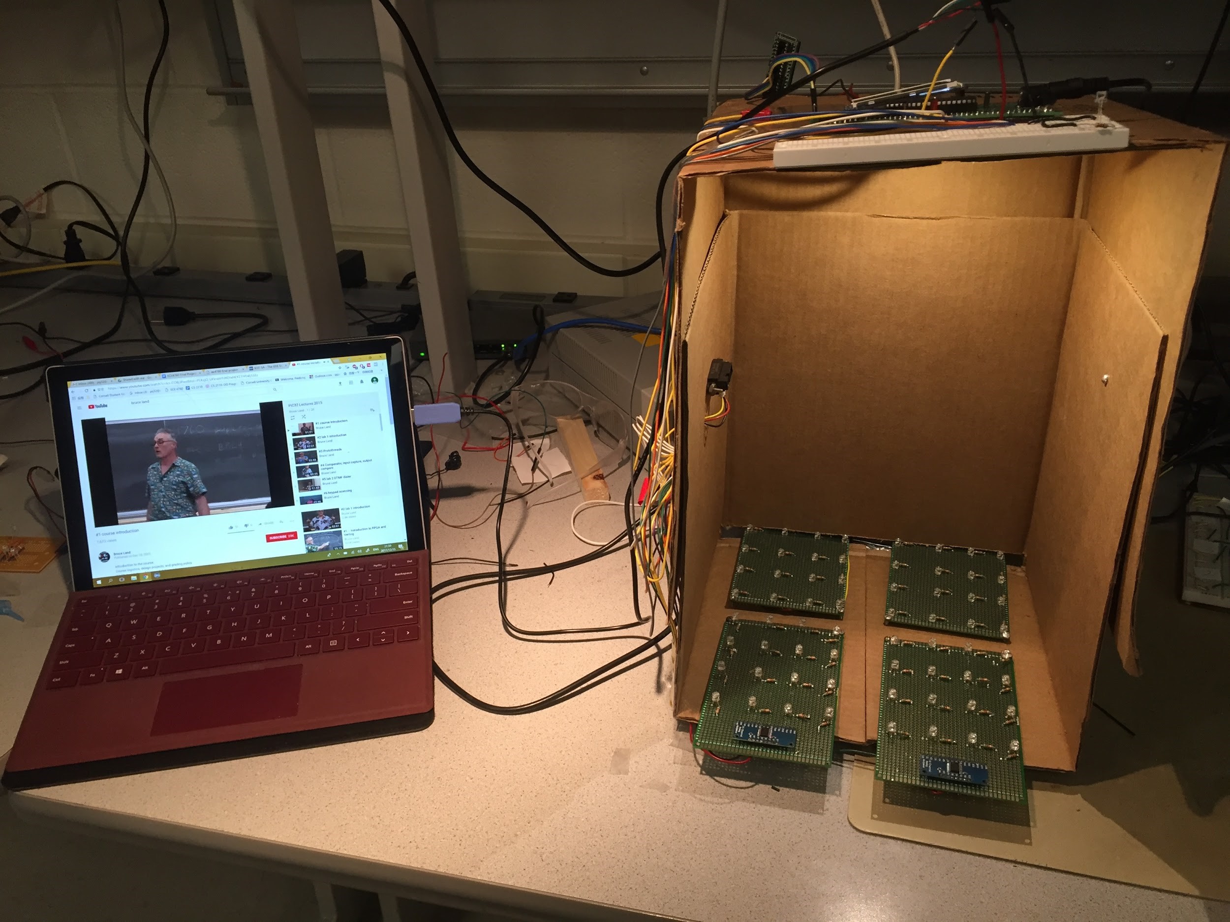
Layout of the entire system
Things didn't work
Initially, we intended to use a combination of distance sensors and phototransistors readings for recognition of commands: volume up, volume down, move forward, and move backward. But the combination did not give us the most optimized results because the shadow at the bottom of the box can mess up with different commands. For example, for move forward command, we wanted to determine the event when the distance value is decreasing and there is a single line of shadow moving from right to left side on the phototransistors layout. But for volume up command, when the hand is raising, the area of shadow is increasing. However, it covers most of the area on the phototransistors layout, which can overlap with the single line of shadow recognition. We tried to implement the system in this way but it did not give us the best recognition results. When we tried to use the distance sensors solely for recognition, however, the system gives better recognition results.
Result
Pictures & Video demo
As mentioned above, the implemented commands are: Speed up, Slow down, Mute/Unmute, Enter/Exit fullscreen, Pause/Resume, Volume up, Volume down, Move forward, Move backward. All of the commands are working properly and have little mis-recognition during our tests. Below are the results seeing from TFT display.
demo video
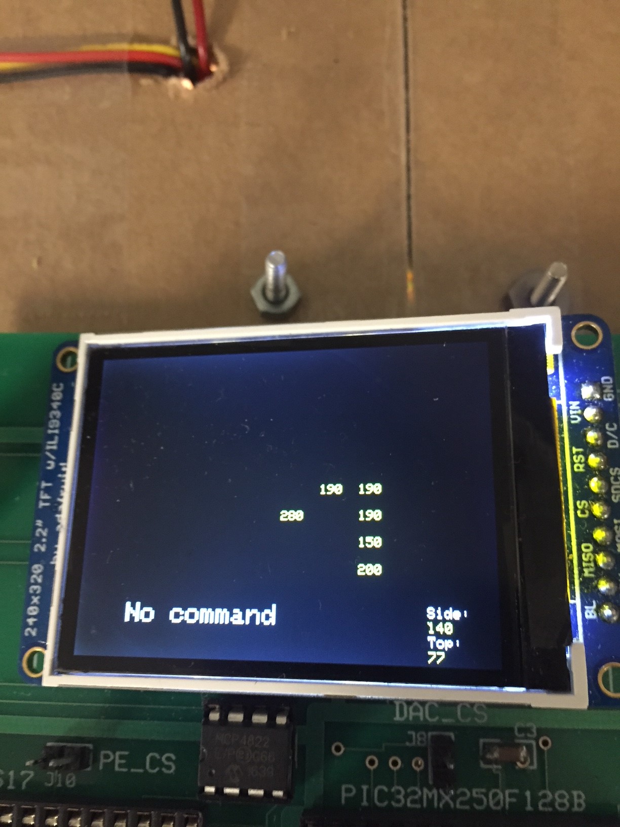
TFT display with no command
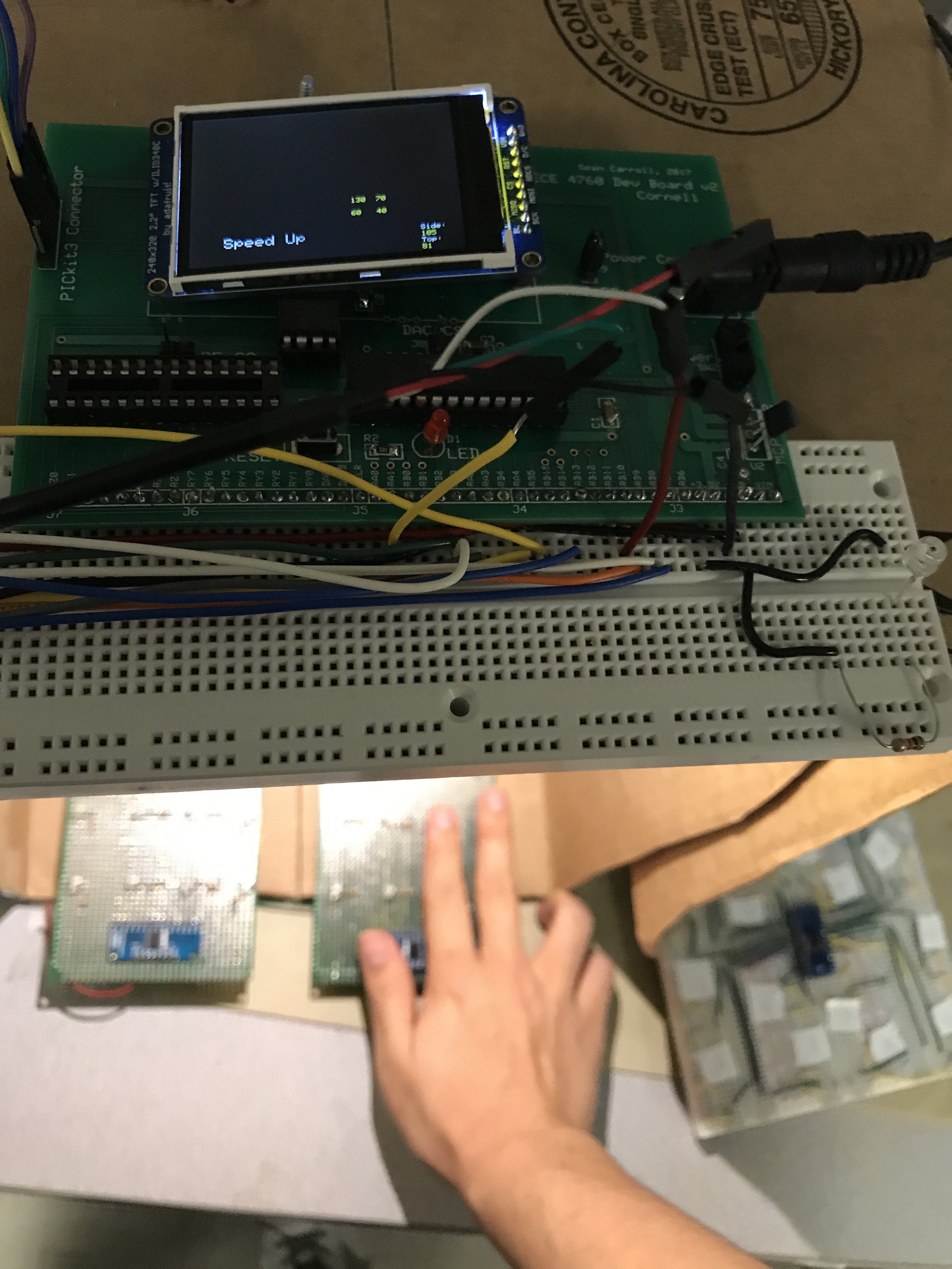
TFT display when a user wants to speed up the video
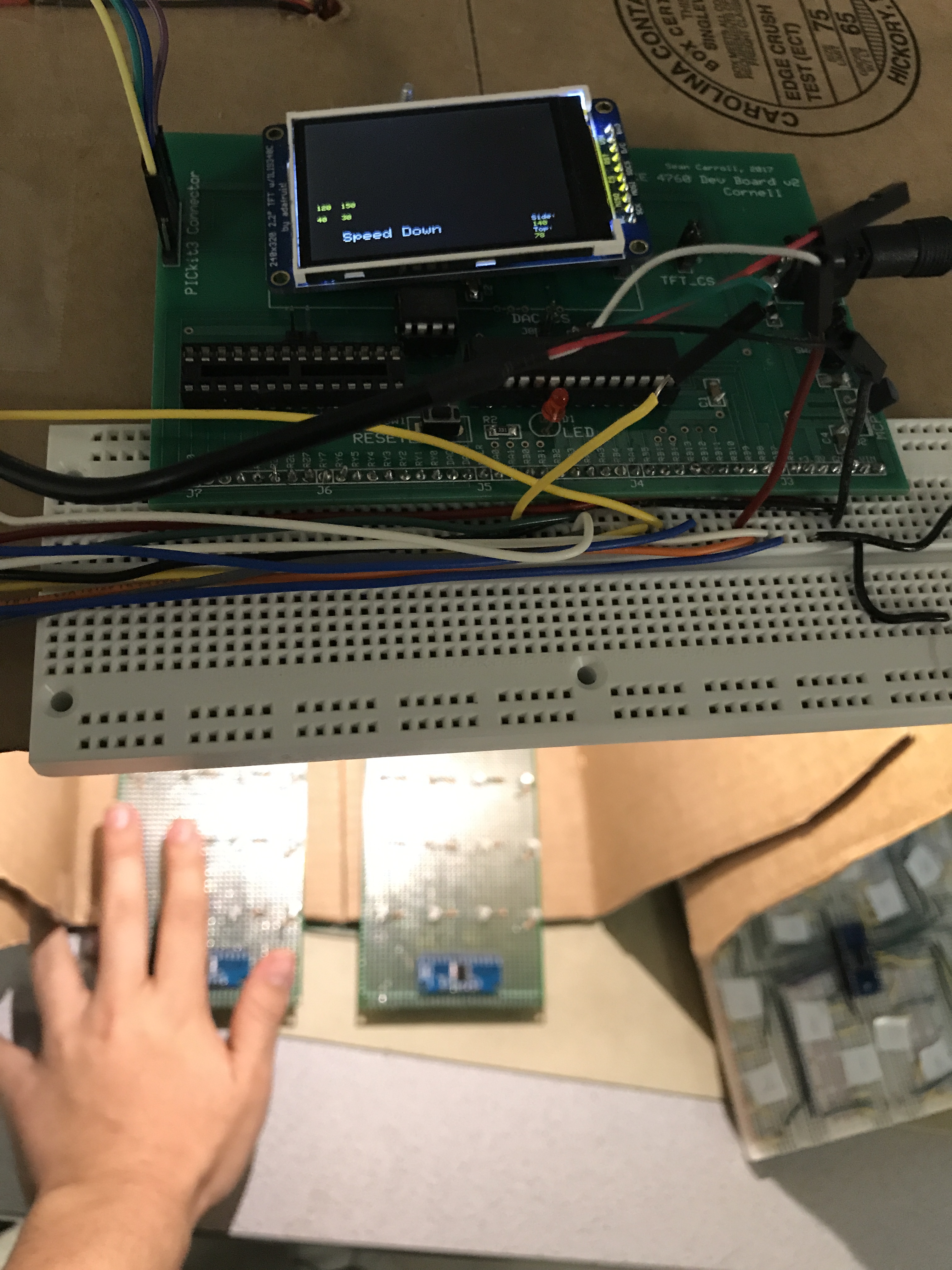
TFT display when a user wants to speed down the video
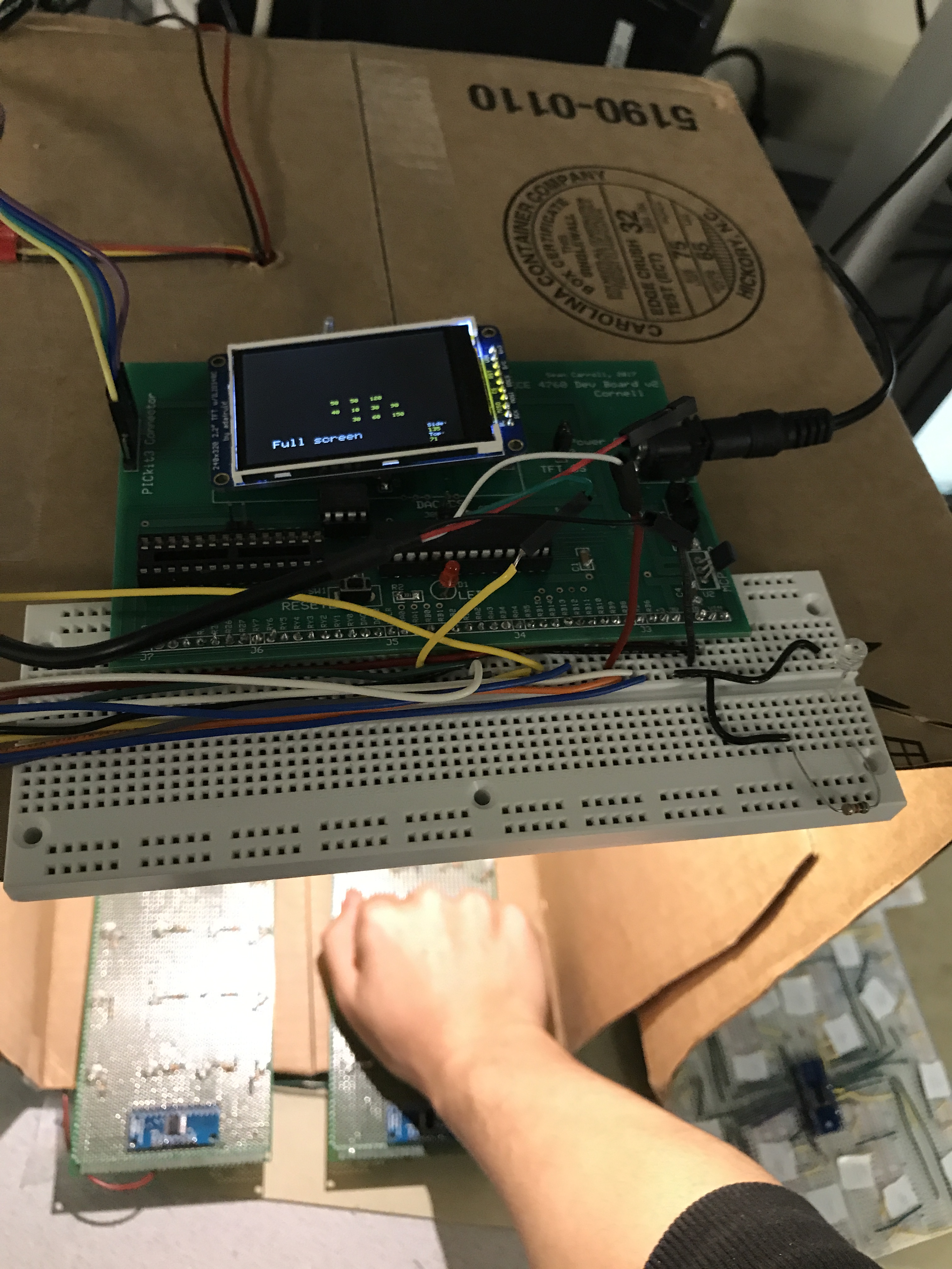
TFT display when a user wants to enter/exit full screen mode
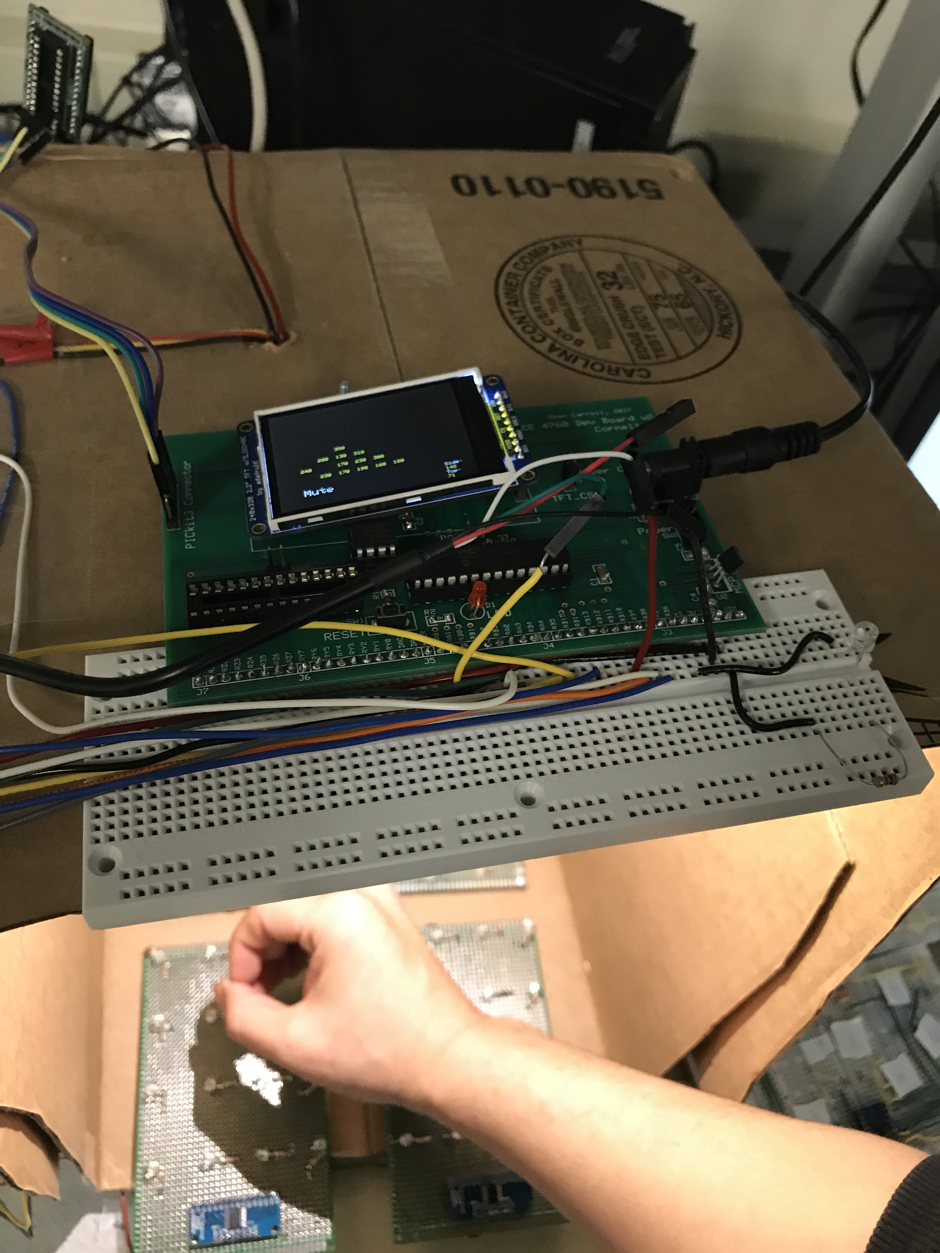
TFT display when a user wants to mute/unmute the video
TFT display when a user wants to pause/resume the video
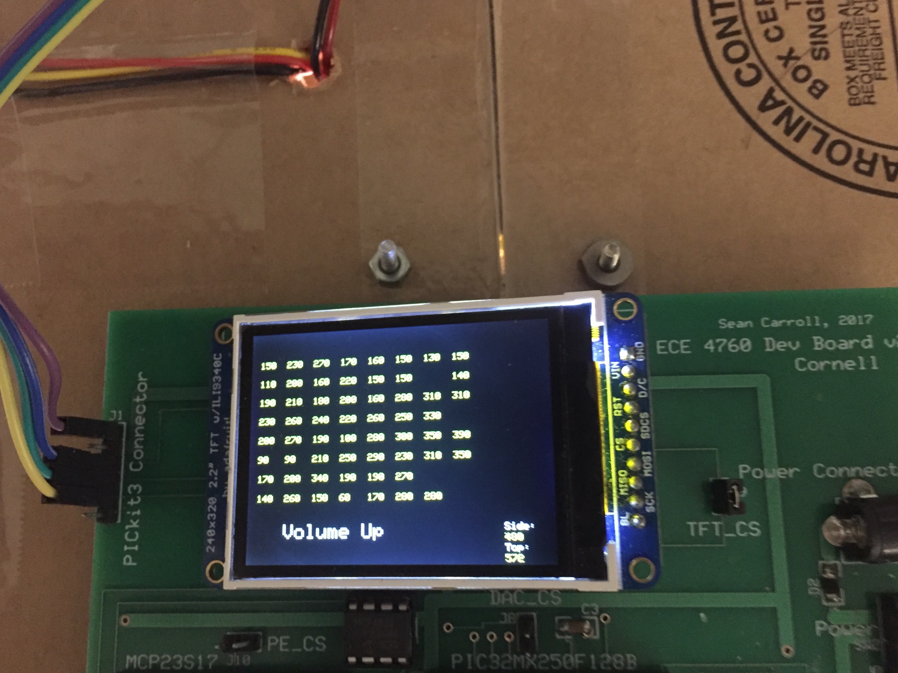
TFT display when a user wants to turn video volume up
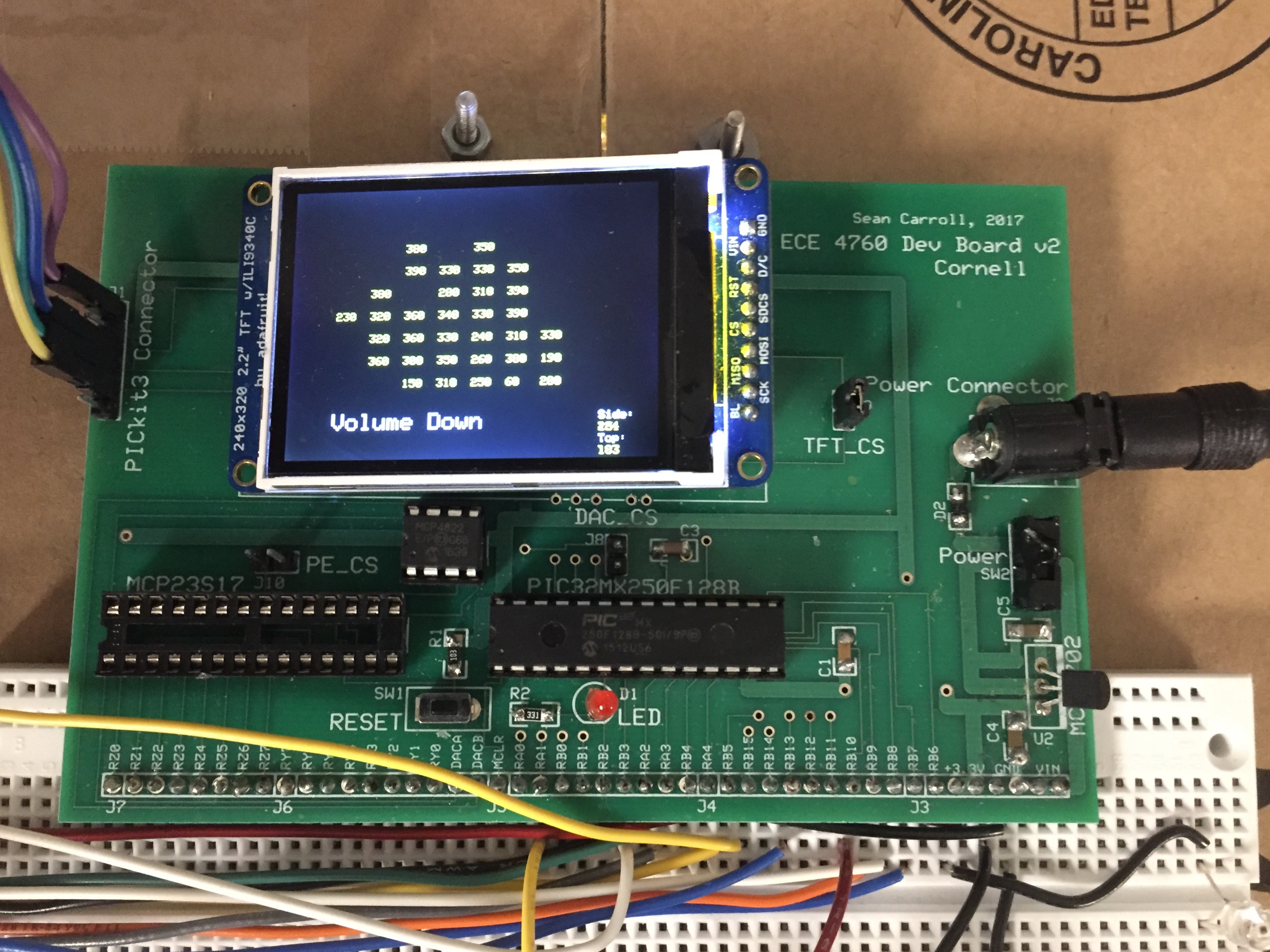
TFT display when a user wants to turn video volume down
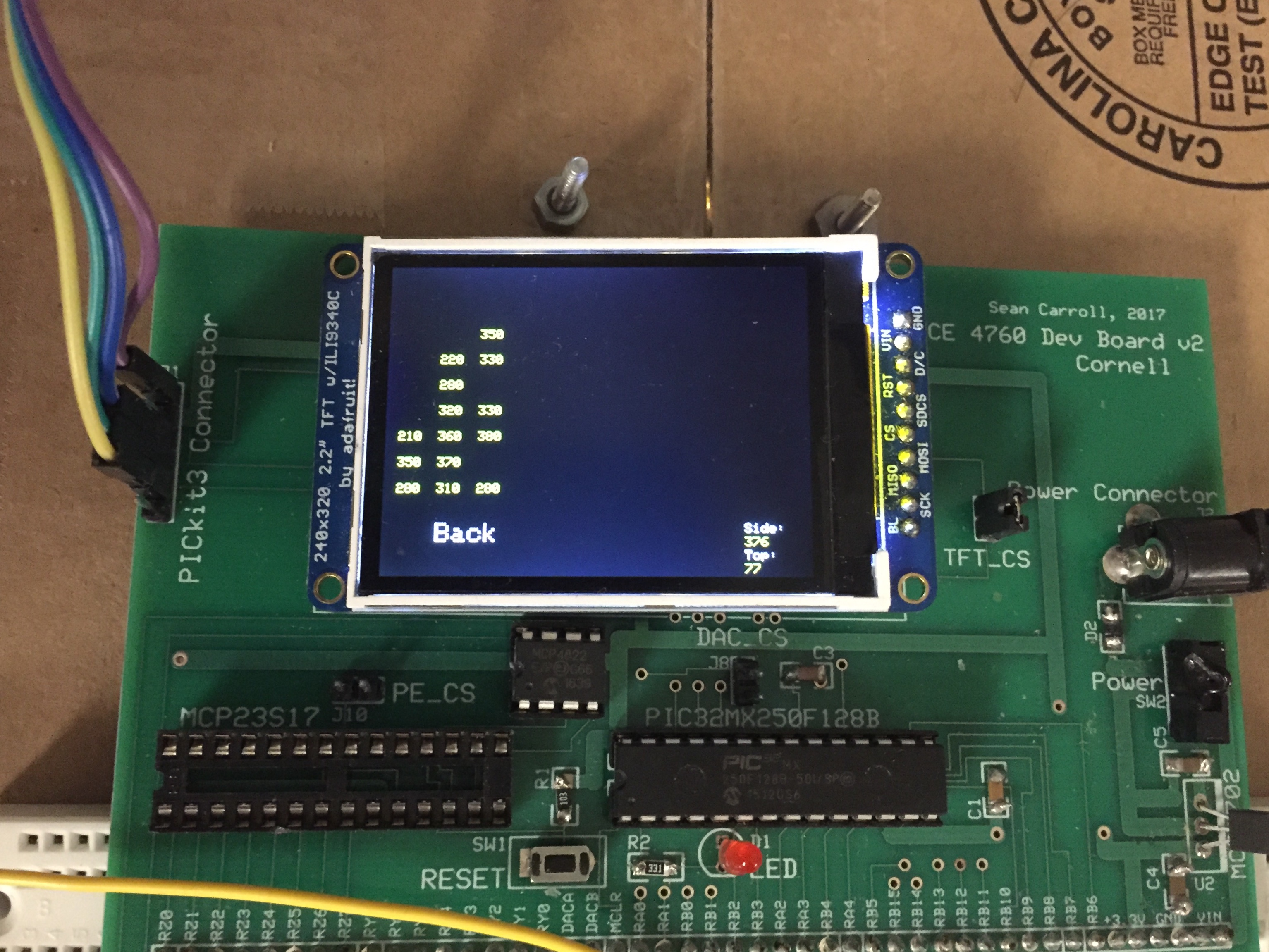
TFT display when a user wants to move video backward for 5 seconds
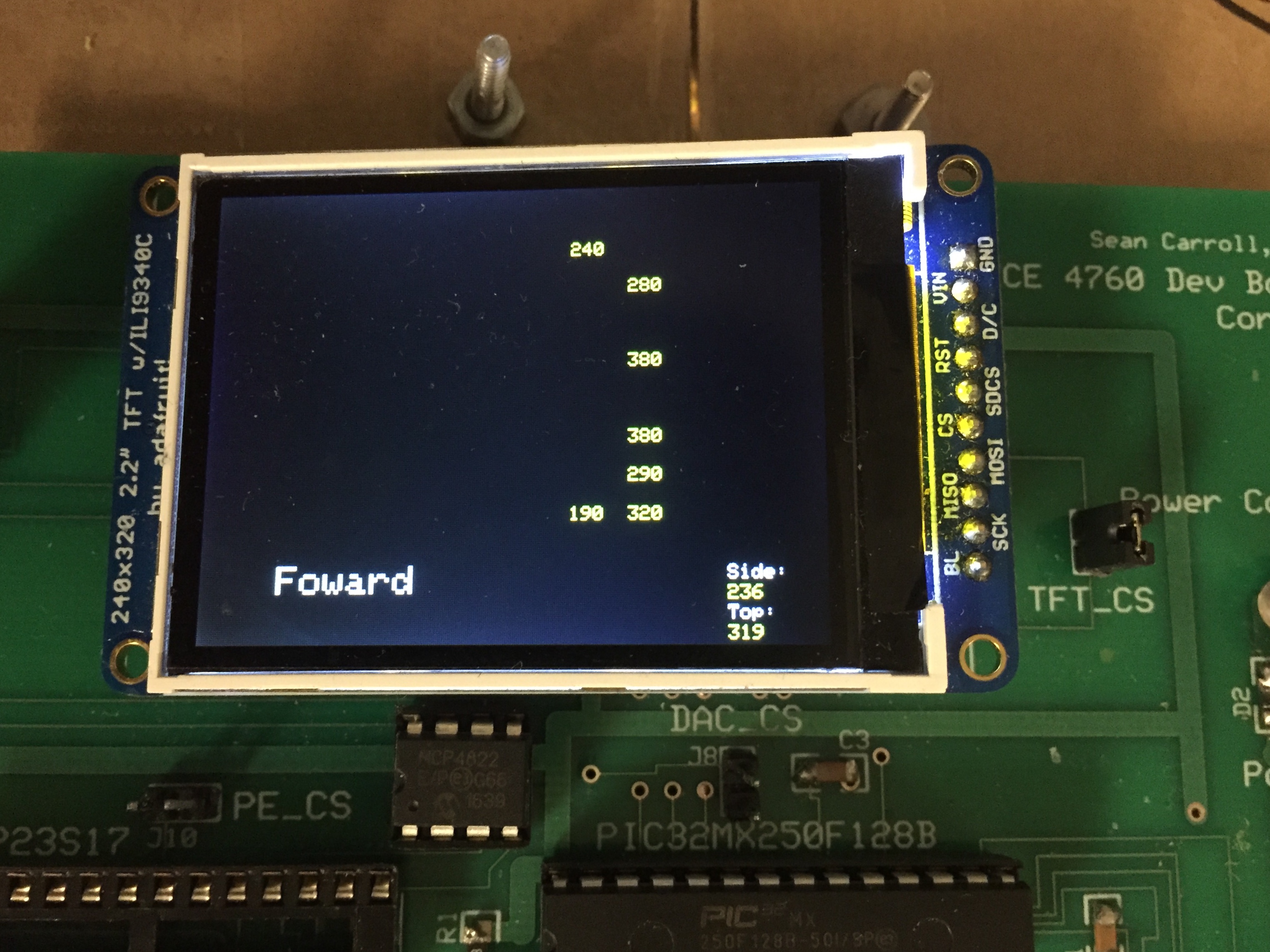
TFT display when a user wants to move video forward for 5 seconds
Time of Execution
For the final demo, everything we worked fine and there is little time delay. The time delay in the system are measured to be approximately 0.1 second and it is nearly negligible. There was a time during the development when the time delay was like 0.5 second between TFT update. We thought about reducing the number of phototransistors to decrease the time delay. It was a trade-off between accuracy and time delay because we would have less phototransistors readings for recognition. Ultimately, we removed extra framework on the TFT and reduce the time delay without decreasing the number of phototransistors.
Though we are doing well, there is still room for improvement. Currently, after setting up ports and bits, we used an available API on the ECE 4760 website to wait for 1 millisecond for the ADC to be ready. We could write new method in C language ourselves and wait the length of time as long as the length is more than the one specified on the datasheet of the 16 channel multiplexer.
Accuracy
Our system accuracy has been dramatically increased during our consistent refinement and optimization. For our first design with 64 phototransistors and distance sensors, we got an average accuracy of 58%, mostly because the interference between different sensors and overlap among different hand gestures. After separating sensors for independent work and new algorithm to recognize the hand gestures , we were able to boost the accuracy up to 83%.
| Command | Tested | Worked | Accuracy(Worked/Tested) |
|---|---|---|---|
| Speed up | 10 | 10 | 100% |
| Slow down | 10 | 10 | 100% |
| Pause/Resume | 10 | 8 | 80% |
| Mute/Unmute | 10 | 9 | 90% |
| Enter/exit fullscreen | 10 | 8 | 80% |
| Volume up | 10 | 8 | 80% |
| Volume down | 10 | 7 | 70% |
| Move forward | 10 | 7 | 70% |
| Move backward | 10 | 8 | 80% |
Accuracy table based on the tests
Safety and usability
Safety is always our first priority. We thought about implementing an autonomous tank which can shoot golf balls for an international competition. But it has countless safety concerns and it was hard to test. Our current project is fairly safe in term of usability. The power supply will provide 3.5V voltage and all the other sensors are consuming 3.3V power from PIC32. There is no detrimental light to human naked eyes, nor sharp edges from the circuits.
To keep our system safe, we put the system on a paper box and users need to put their hands into the box and hold gestures. To avoid ESD harm to the circuit, we did everything on a ESD safe mat.
Interference
No significant interference has been observed throughout the development process.
Conclusion
Overview
Over all, we have achieved all the goals we have made at the beginning of the project. We successfully constructed a hand gesture video controller. For this project, the 64 phototransistors and two distance sensor are functionally working. We can detect the shape of shadow with 64 phototransistors and location of the hand with 2 distance sensors. Our product can recognize nine different hand gesture. It then sends the command to a PC, the PC are able to recognize those commands and process the corresponding action to Youtube video player. For this project, we have enhanced what we have learned in this course. We also learned some new stuff about PIC32, for example, we have expand the ADC ports from two to three.
Although we have achieved all our goals, we think there still have a lot of space to improve. We have used distance sensors and phototransistors. However, we did not combine those two together. Each part only works independently but not together. In the future work, we may try to implement distance sensor and phototransistors together. That could make the result more accurate. Another plan is only using phototransistors for the product, we can add four more LED light on the four top corners in the box. Each time, we only open one LED light and scan the phototransistor matrix. Then we will have five different shadow matrixes. By analyzing those five matrixs, we can know the location, movement and shape of the hand. The result could potentially be more accurate.
Intellectual Property Considerations
For the hand_gesture_video_control.c code, all the work belong to our own. We have created the template matrix for the shadow. We reuse part of code from the Eye Mouse project as cited in our reference section. We only use the serial port set up part for our java program. The rest of code are our own works.In our research we found no proof that our project infringes on any existing patents
Ethical Considerations
We adhered all the stages of IEEE code of Ethics for our project. With regards "to hold paramount the safety, health, and welfare of the public, to strive to comply with ethical design and sustainable development practices, and to disclose promptly factors that might endanger the public or the environment;" Our entire system uses a 5V power supply which is no harm to the public or environment. For the stander.5 “to improve the understanding by individuals and society of the capabilities and societal implications of conventional and emerging technologies, including intelligent systems”, our purpose for this project is to use technology to improve people’s life quality. With the application of our product, we help people understand and make it easier to accept this new technology. During the project, we assisted each other in our professional development. We also encourage each other to follow the IEEE Ethical code. Furthermore, we offer our professional knowledge to other group. For example, We have successfully made distance sensor work. There was another group also used distance sensor which was not working. Then we helped them to figure out the hardware and software issues that caused distance sensor not working. For this project, we have made numerous mistake and took some wrong path. However, we accept others’ suggestion and are willing to admit and correct our mistake. When we hit the road block, we would seek help from Professor Land and TAs. Here we want to thank Professor Land and TAs’ help. Without them, we could not finished the project smoothly.
Legal Considerations
There is no legal consideration in our project. We used usb cable to transfer our data instead of wireless transmitter. We have not use any device may harm to human. And we did not infringe any Intellectual Property.
Appendix
Appendix A
The group approves this report for inclusion on the course website.
The group approves the video for inclusion on the course youtube channel.
Appendix B: program listing
keyboardcontrol.java
hand_gesture_video_control.c
Appendix C: schematics
schematic
Appendix D: Cost list
| Part | Unit cost | Unit | Total |
|---|---|---|---|
| Infrared Proximity Sensor | $14 | 2 | $28 |
| Double-Side Prototype PCB | $2.07 | 4 | $8.28 |
| CD74HC4067 16 channel Multiplexer | $4.76 | 4 | $19 |
| Phototransistor | $0.38 | 64 | $24.3 |
| PIC32 Big board | $10 | 1 | $10 |
| TFT LCD | $10 | 1 | $10 |
| White board | $6 | 1 | $6 |
| Wires & Others | $10 | ||
| Total | $115.58 |
Appendix E: Work Distribution
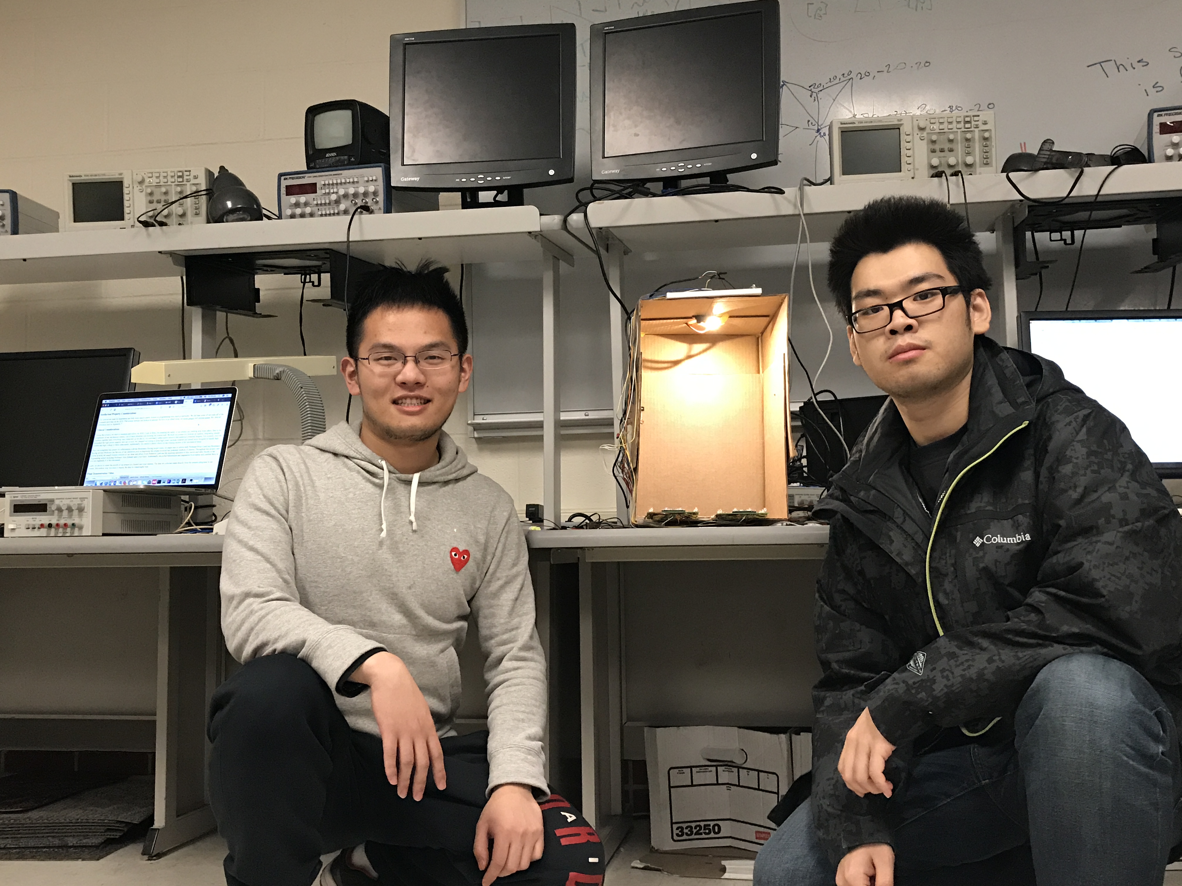
Project group picture
Peidong Qi
pq32@cornell.edu
Designed and implemented the JAVA program
Designed and implemented the hand_gesture_video_control.c program
Built the PCB board
Connect the circuit of final prototype
Weiyou Dai
wd248@cornell.edu
Built the PCB board
Built the 8 to 1 MUX prototype
Built the 16 to 1 MUX prototype
Designed and implemented the hand_gesture_video_control.c program
Appendix F: References
ipixel LEDInfrared Proximity Sensor Datasheet
CD74HC4067 16 channel Multiplexer
CD405xB CMOS Single 8-Channel Analog Multiplexer
PIC32 datasheet
UART
Java Robot AWT class Document
Eye Mouse project