
Haptic Feedback Weathervane
Designed by Reuben Rappaport and Keyi Ruan
Introduction
When sailing a boat, one of the most important factors is the direction of the wind. If they want to keep a steady heading, sailors need to be able to dynamically adjust the direction they steer as the wind changes. Unfortunately, the ability to tell exactly which direction the wind is blowing can be a difficult skill to learn.
In this project we set out to create a device that would enhance and extend people's senses, almost as if they had an innate ability to tell the direction of the wind. To do this we built a haptic feedback belt that uses embedded vibration motors to vibrate in the direction of the wind and a matching weathervane that streams wind readings to the belt over bluetooth.
High Level Design
Rationale
When we brainstormed final project ideas, we really focused on designing devices that could enhance and extend people's senses. Keyi was taking a sailing class at that time and she pointed out that we could help sailors by enhancing their ability to distinguish the direction of wind. We both thought this could be an interesting topic for our final project and started researching its feasibility. After some estimation on the budget, time, and achievability of this idea, we decided to proceed with it.
Logical Structure
The project consisted of a weathervane and a haptic feedback belt.
The weathervane detected the wind direction through the arrow on top and the wind speed through the wind cups at bottom. It streamed wind readings to the belt over bluetooth.
Upon receiving the data, the belt vibrated the corresponding motors to notify the user of the wind direction relative to the user's heading. We evenly placed the eight vibration motors around the belt at 45 degree intervals. We interpolated linearly between each pair of motors when the direction did not reach a motor exactly.
Hardware/Software Tradeoff
We faced a multitude of hardware design challenges working on this project. When designing the weathervane assemply, we faced challenges of choosing the proper sensors to detect wind directions and speed, designing a physical device that could mount the desired sensors while maintaining the functionality of a weathervane, and hiding all the electronics from the user interface. When designing the haptic feedback belt, we faced challenges of mounting the compass module in fixed position on the belt and designing the circuit to drive eight viberation motors given the limited amount of pins on the small board. The software part of the project was relatively easy and straightforward. We encountered some problems on caliberating the 3-axis accelerometer and compass and we had to scale back our project scope slightly to make this prototype working. Generally we preferred to do things in hardware when possible - using physical sensor modules to detect readings, and multiplexing the motors through actual AND chips rather than in software.
Relevant Standards
For communication between the weathervane and the belt, we used two HC-05 bluetooth moduels, which conformed to standards set out by the IEEE Bluetooth Special Interest Group (SIG). Specifically, the standard we followed was IEEE 802.15.1. Since we did not modify these modules, their preexisting certification is still valid
Intellectual Property Considerations
All source code was produced by the members of the group and external packages such as protothread were used with permission from the instructor (Bruce Land). All analog circuit designs and external modules were adapted from open-sourced, publicly available schematics.
Hardware Design
Overall Architecture
The hardware used in this project was divided into two main assemblies - the haptic feedback belt, and the weathervane. The belt assembly consisted of
- A standard leather belt
- Eight vibration motors taped to the belt at forty-five degree intervals
- A compass module
- A bluetooth module
- The PIC32 microcontroller on a small development board
- A 9V battery used as a power supply
We soldered down a control circuit connecting the development board to the motor using a piece of solderboard
The weathervane assembly consisted of
- A black cardboard electronics box used as the base
- A set of wooden supports located inside the box to add additional structure and rigidity to it
- A 1" diameter piece of aluminum pipe used as the central shaft
- A set of 3D printed wind cups used to measure the ambient windspeed. These were mounted on a ball bearing and aligned vertically on the shaft using a hefty shaft collar
- A hall effect sensor used to measure the rotation of the wind cups
- A 3D printed wind arrow used to measure the wind's direction. This was also mounted on a ball bearing and aligned using a shaft collar
- A hall effect encoder used to measure the wind arrow's rotation
- Two rare earth magnets - one mounted on the wind cups and another mounted on the wind arrow
- A bluetooth module
- The PIC32 microcontroller on a small development board
- A 9V battery used as a power supply
Again we soldered down our control circuit using a piece of solderboard
Power
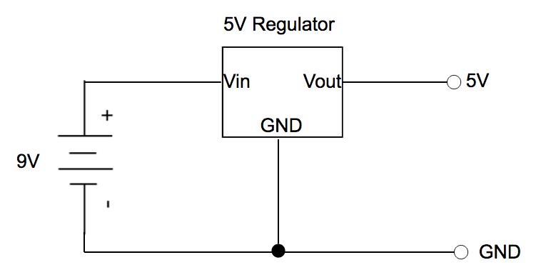
We used the same circuit to power both assemblies. In both cases we ran a 9V battery through a 5V regulator and then ran the 5V output to the microcontroller's voltage input. We chose to do this because several components we used were designed to run at a 5V logic level so it was important to have both 3.3V and 5V levels in our circuit.
Weathervane Base
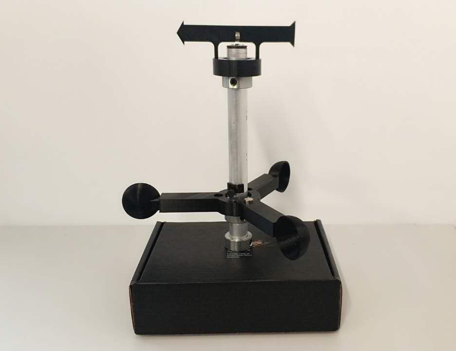
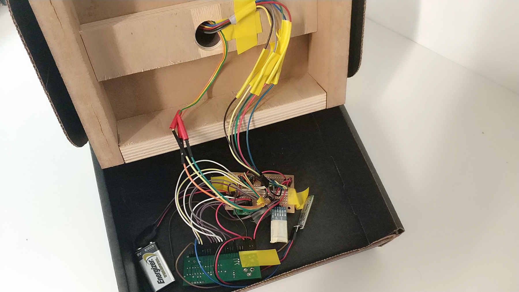
To construct the physical base of the weathervane we used a black cardboard electronics box. We cut some pieces of scrapwood to its interior dimentions and screwed them together, forming a rigid internal support. Then we drilled a 1" diameter hole through the top of the box and the wood. When we tried putting the 1" aluminum pipe through this hole we found that it was fairly tight so we just friction fit it in place and used a shaft collar to stop it from slipping down.
Measuring Wind Speed
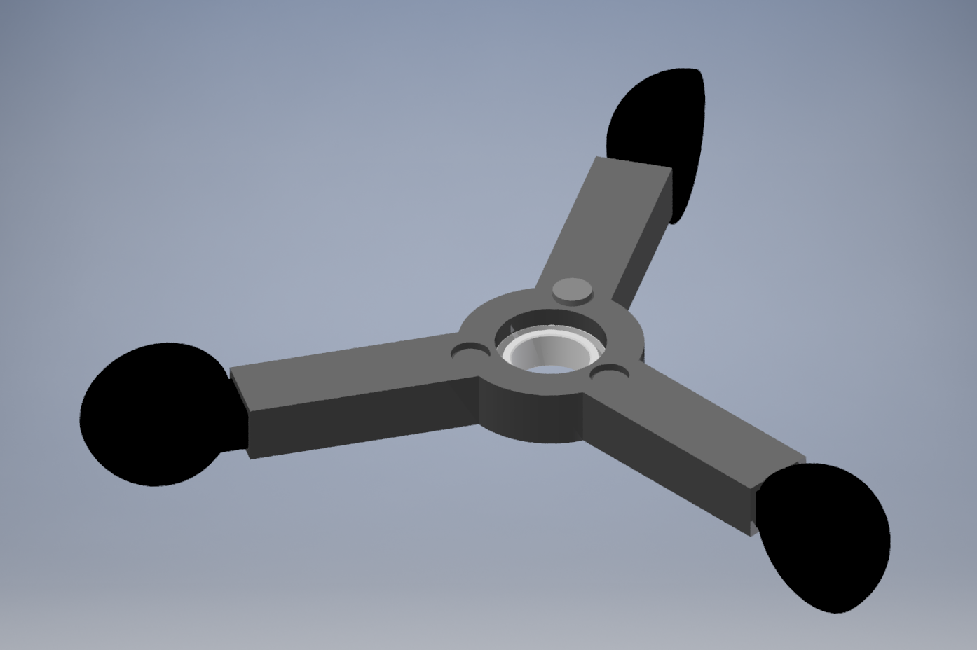
To measure the wind speed we 3D printed a set of "wind cups", which spin in the wind. By measuring their rate of rotation we can calculate how fast the wind is blowing. Since the printing the entire wind cup assembly as a single piece was infeasible we printed it as four separate pieces - the central hub which is mounted on a low friction plastic ball bearing, and three wind cup pieces which are friction fit on the ends of the hub's arms.
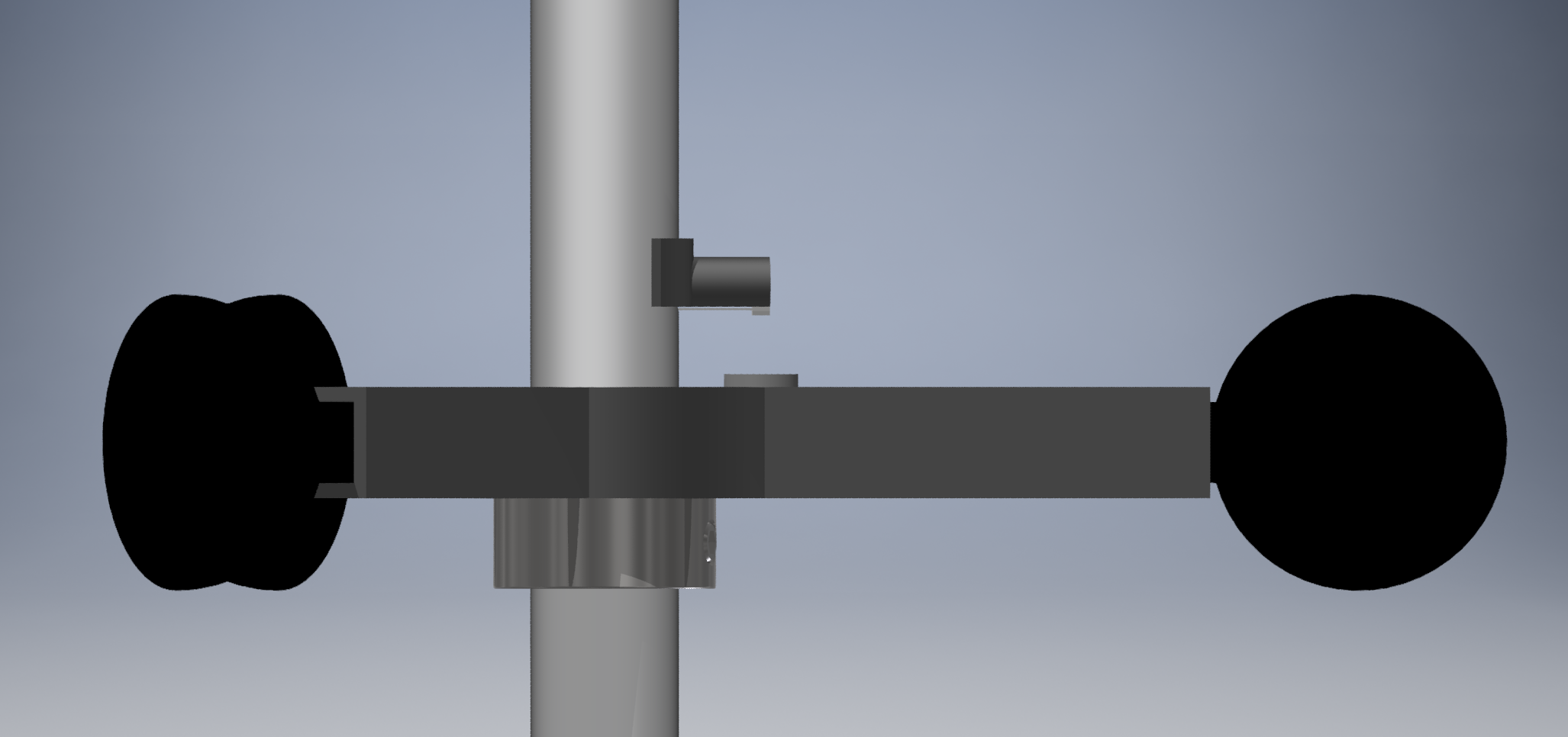
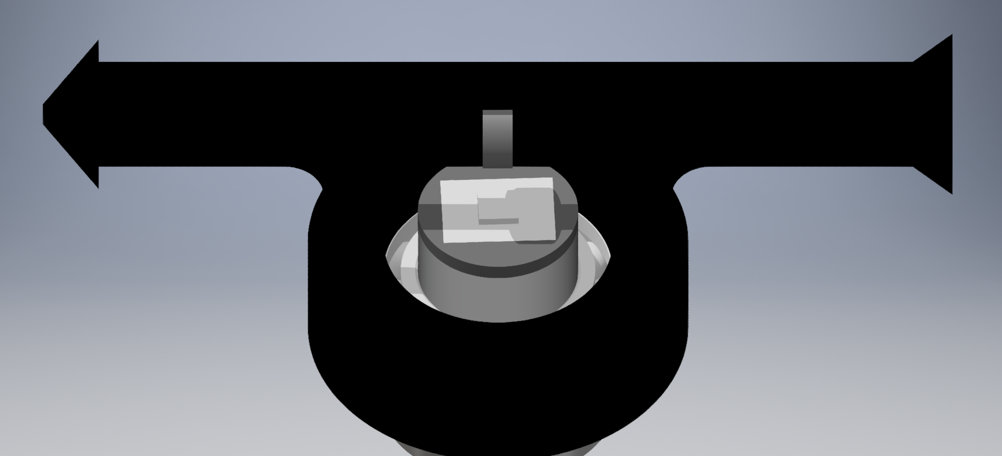
Once we had put the wind cups together and aligned them on the shaft using a shaft collar, we needed to actually sense how fast they were turning. To do this we drilled a hole in the shaft inserted a "plug" piece with a flange. Then we superglued a small hall effect sensor to the underside of the plug and routed the wires through another small hole and into the pipe. We hot glued a rare earth magnet to one of the wind cup arms. This had the effect that every time the wind cups made a full revolution the hall effect sensor would trigger. By keeping track of the time between the pulses the microcontroller could calculate the speed of revolution.
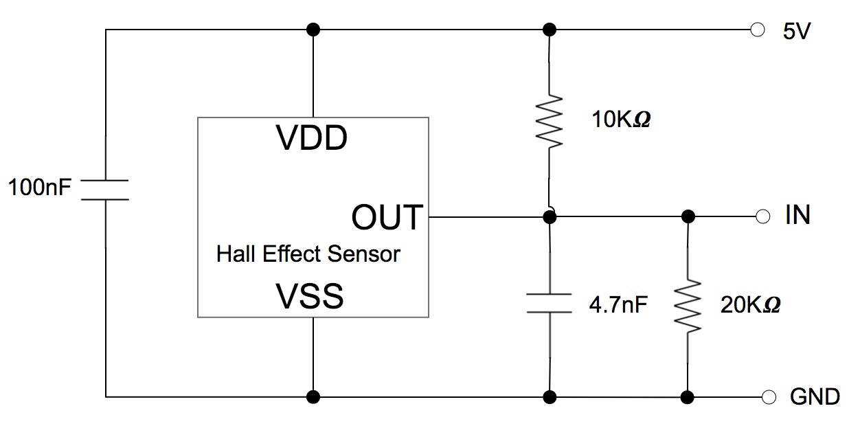
The circuit to wire up the hall effect sensor was fairly simple. We gave it 5V and GND and connected a few capacitors to smooth out its behavior. Since it was a 5V but we were planning to feed it into a microcontroller pin we pulled its output to 3.3V so that it wouldn't kill the I/O port. The behavior with this sensor is to output high when no magnetic field or a north pole is detected and to output low when a south pole is detected.
Measuring Wind Direction
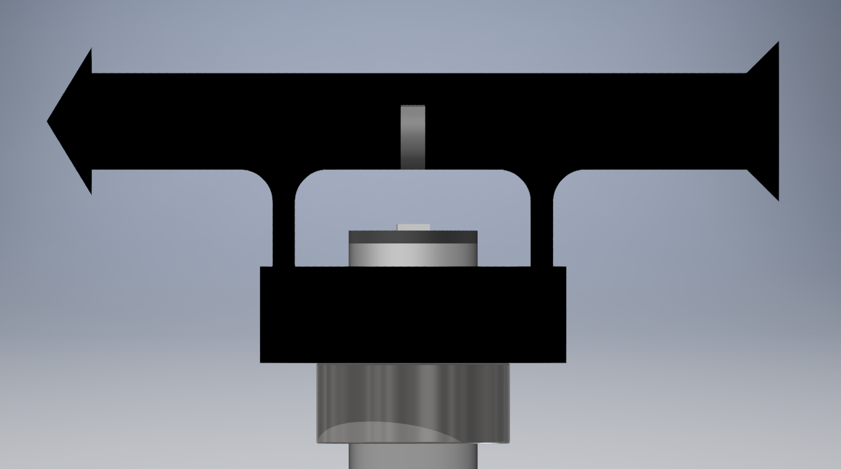
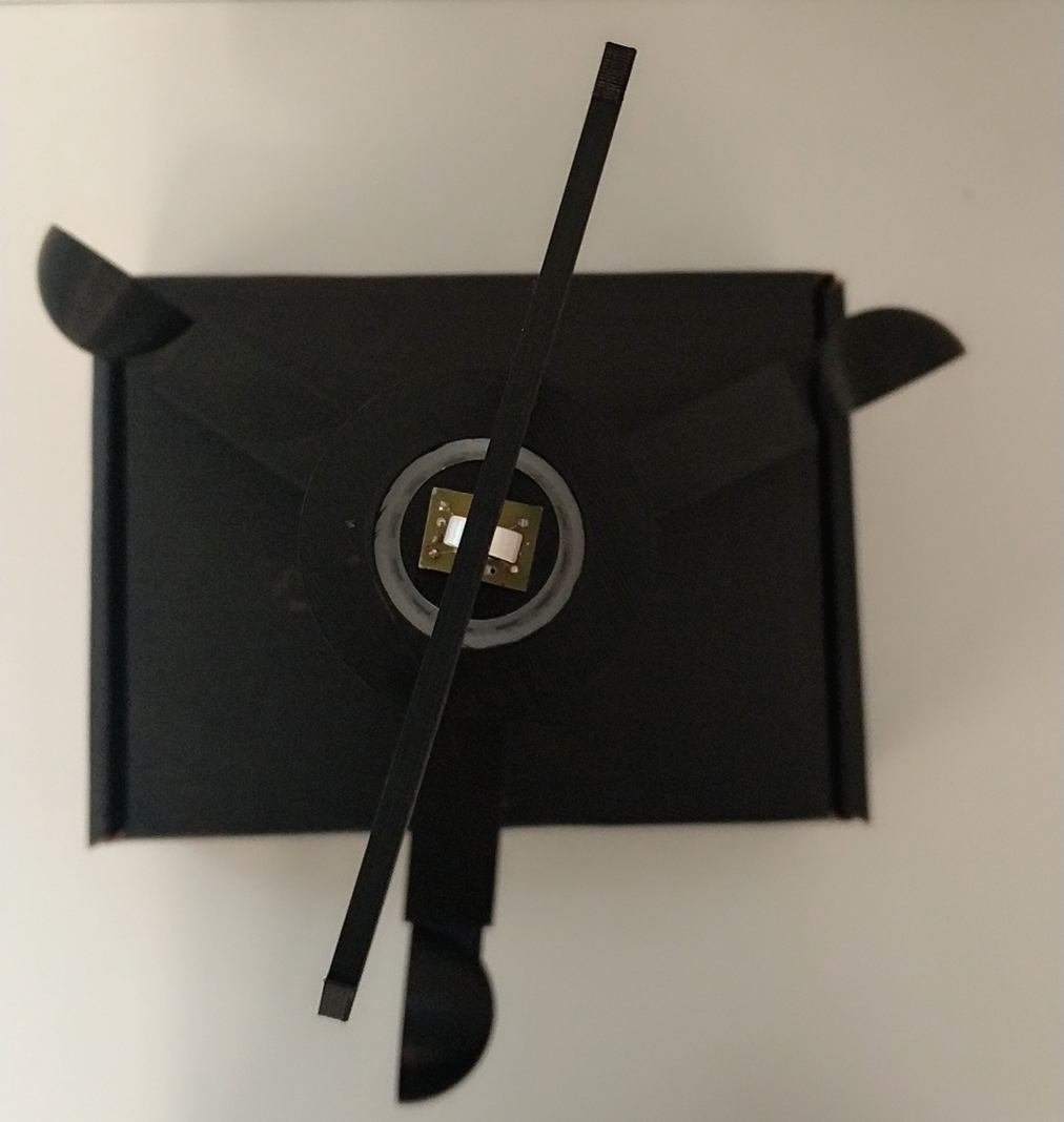
To measure the wind's direction we 3D printed another hub to be mounted on a low friction ball bearing and a classic weathervane arrow with two legs. By placing this hub near the top of the shaft we were able to have the arrow rotate on the bearing while sticking out of the top. We again aligned it vertically using a shaft collar underneath the assembly.
To actually measure the arrow's rotation we used a hall effect encoder module. This device uses multiple hall effect sensors to determine the rotation of a magnet placed directly above it. To place the encoder we 3D printed a plug for the top of the shaft which supported its breakout board while leaving a hole in the middle for the encoder's wires to run straight down the shaft. To place the magnet itself we included a slot in the arrow into which we friction fit a small circular magnet.
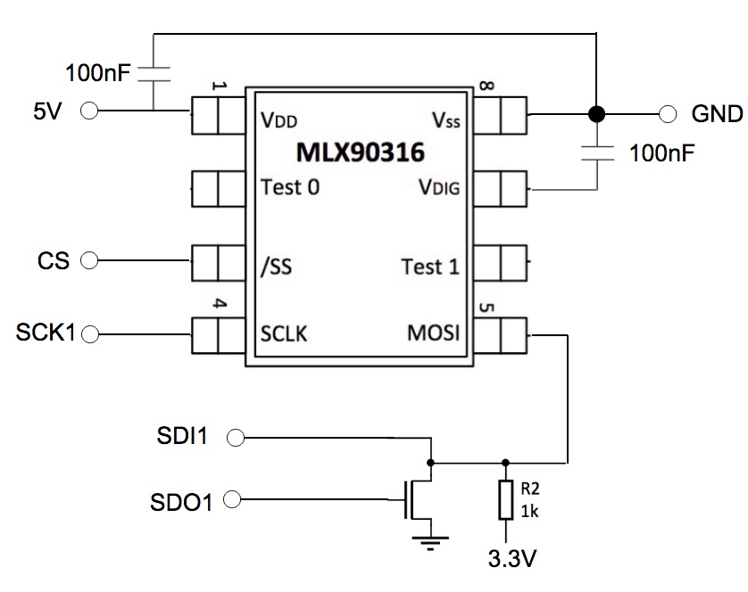
We wired up the encoder over SPI. Unfortunately it used a half-duplex 3 wire version of the protocol with a shared MISO/MOSI line so we had to connect our MISO and MOSI outputs together through a FET. Apart from this peculiarity, it was a pretty straightforward SPI connection.
Measuring Orientation
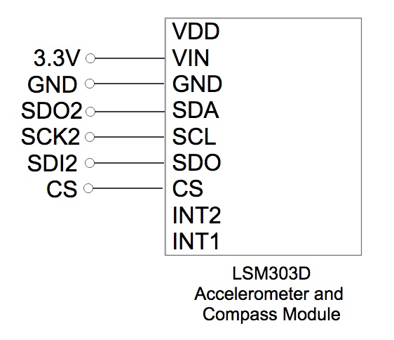
To get the heading direction of the weathervane and the user, we wired up the 3-axis accelerometer and compass module over SPI. Since the module had a voltage regulator built in, we simply gave it 3.3V to the Vin port.
Transmitting Over Bluetooth
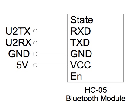
To send wind readings from the weathervane to the belt, we wired up the bluetooth module over UART on both the belt and the weathervane. Once connected and paired up, the microcontrollers were able to communicate as if there was direct serial connection between them. Using the bluetooth modules for data transmission, it was also easy for us to test our code since we could simply connect a serial cable to the module on the other side of the connection and view what was being sent back and forth in our serial monitor.
Belt Base
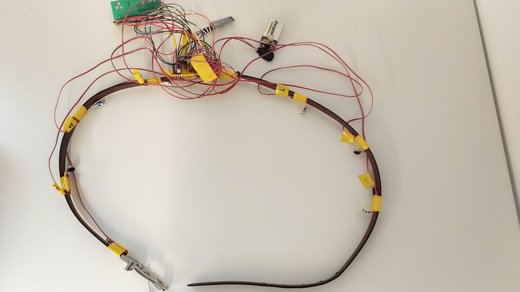
The eight motors were evenly placed on the belt at 45 degree intervals. The solder board with the compass module mounted was fixed vertically against the belt. The PIC32 board, bluetooth module and 9 Volt battery were soldered onto the solder board using jumper wires.
Controlling Vibration Motors
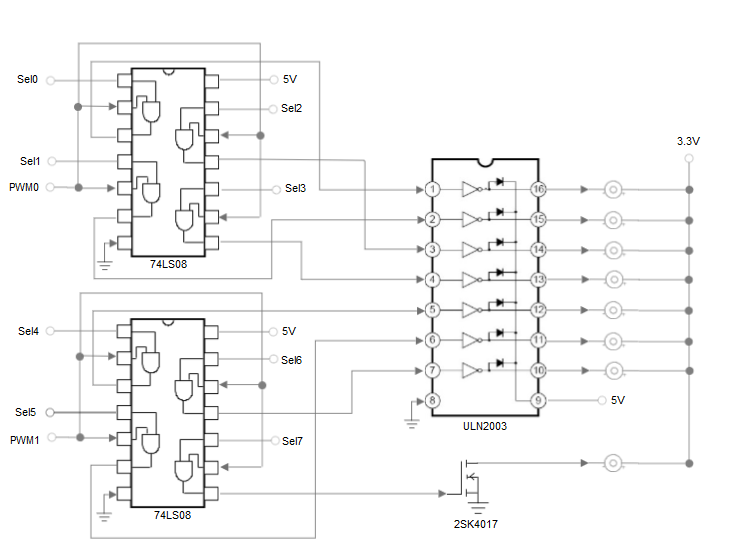
 To drive all eight motors on the belt, we assigned two output compare pins and eight select pins on the PIC32. We used two Quadruple 2-Input Positive-And Gate 74LS08 chips, one ULN2003A motor driver and one 2SK4017 NFet to wire up the circuit. With each the AND gate, the first input was connected to the corresponding select pin on the PIC32 and the second input was connected to a shared PWM line, which was connected to the corresponding OC pin on the PIC32. We decided to let the four AND gates on the same chip share a PWM line to make the entire circuit clean and organized. The output pin on each AND gate was connected to an input pin on the motor driver. Since the ULN2003A chip only supports 7 Input-Output pairs, we added an extra NFet to drive the remaining motor. The outputs of the motor drivers were then fed to the vibration motors.
When we physically attached the motors to the belt we placed them in the pattern 0, 4, 1, 5, 2, 6, 3, 7. This meant that any pair of adjacent motors were driven using different PWM lines and could be adjusted independently. This property was key to our ability to antialias the vibration direction.
To drive all eight motors on the belt, we assigned two output compare pins and eight select pins on the PIC32. We used two Quadruple 2-Input Positive-And Gate 74LS08 chips, one ULN2003A motor driver and one 2SK4017 NFet to wire up the circuit. With each the AND gate, the first input was connected to the corresponding select pin on the PIC32 and the second input was connected to a shared PWM line, which was connected to the corresponding OC pin on the PIC32. We decided to let the four AND gates on the same chip share a PWM line to make the entire circuit clean and organized. The output pin on each AND gate was connected to an input pin on the motor driver. Since the ULN2003A chip only supports 7 Input-Output pairs, we added an extra NFet to drive the remaining motor. The outputs of the motor drivers were then fed to the vibration motors.
When we physically attached the motors to the belt we placed them in the pattern 0, 4, 1, 5, 2, 6, 3, 7. This meant that any pair of adjacent motors were driven using different PWM lines and could be adjusted independently. This property was key to our ability to antialias the vibration direction.
Software Design
Overall Architecture
The software for this project was split into two sections - weathervane.c and belt.c which respectively ran on the weathervane and belt's microcontrollers. We used the protothreads library for mulitithreading.
weathervane.c was structured as follows:
- A
mainfunction which sets everything up and then schedules the threads round robin forever - A
pt_bluetooththread which periodically sends the latest readings over bluetooth to the belt - A
pt_hall_effectthread which polls the hall effect sensor and updates the wind speed estimate when it triggers - A
pt_timeoutthread which zeroes the wind speed estimate when a sufficiently large amount of time has elapsed since the hall effect sensor last triggered - A
pt_encoderthread which periodically talks to the hall effect encoder over SPI and updates the wind direction reading
belt.c was structured as follows:
- A
mainfunction which sets everything up and then schedules the threads round robin forever - A
pt_motorsthread which yields until it receives a reading over bluetooth and then updates the state of all the vibration motors to reflect it - A
pt_compassthread which periodically talks to the compass over SPI and updates the belt heading
Talking to the Encoder
The encoder we used exchanged data in 10 byte frames. To start the transaction the master would write OxAA followed by OxFF. The encoder would then respond with two bytes of data, the same two bytes of data inverted, and then four bytes of 0xFF. We hooked it up to the SPI2 module on the PIC32 and set up a thread to periodically poll it and read its heading.
Talking to the Compass
The compass we used was a 3-axis accelerometer and magnetometer which we hooked up to the SPI1 module on the PIC32. Our code started by writing to its control registers to configure it. After turning it on, we set up a thread to periodically query it and read out the current acceleration and magnetic readings from each axis. This was designed to be used as a tilt-compensated compass where you first calculate the orientation using the acceleration data and then calculate the heading. However, we were able to simplify the math by assuming that the compass was vertical on the belt, making the heading just atan2(mz, my). To ensure that this was actually true we carefully taped the solderboard to the belt in a vertical orientation.
Measuring Wind Speed
To measure wind speed we set up a thread which yielded until the hall effect sensor's pin went low. There are inherent accuracy concerns with doing this sort of polling (using an input capture unit and an interrrupt would be far more accurate) but since our chief concern was determining the answer to the binary question "is there wind at all" we were not overly concerned with that sort of fine grained accuracy.
When the hall effect sensor triggered our thread updated the RPM estimate based on the time since it last went off. In order to ensure that when the wind stopped completely the RPM would be set to zero, we also created a timeout thread which yielded until a sufficient amount of time had elapsed since the hall effect sensor last triggered. When this happened the timeout thread would set the RPM to zero.
Transmitting over Bluetooth
We used a pair of bluetooth modules mimicking a serial port. We set them up to pair automatically when powered with no need for intervention from the microcontroller. After they had been paired, the microcontrollers could just pretend that there was a direct serial connection between them.
On the weathervane side we set up a thread which periodically pusehd readings out over this serial connection. On the belt side we set up a matching thread which yielded until it received a reading and then updated the state of the vibration motors based on it.
Antialiasing the Vibration Motors
To actually vibrate the motors in the direction of the wind the first thing we had to do was calculate the wind's direction relative to the belt. Since the compass gave us the belt's heading relative to north and the weathervane gave us the wind's heading relative to the same reference point, this was fairly straightforward to do.

After we had figured out which direction to vibrate we had to actually map that to a set of motors. We assigned each motor a five degree range centered on its position (so -2.5 to +2.5 for motor 0, 42.5 to 47.5 for motor 1, etc). Directions in this range just resulted in the corresponding motor vibrating at full power. In the forty degree range between each pair of motors we linearly interpolated the PWM signal assigned to the motors to simulate a vibration coming from between the two. We were able to do this because we alternated which PWM line was assigned to each motor going around the circle.
Results
Physical Results
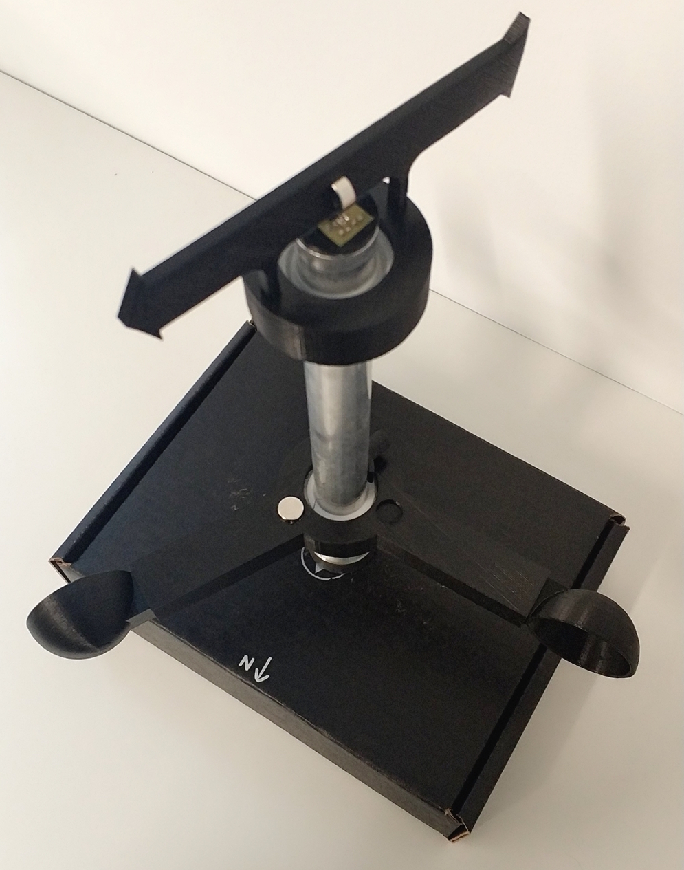 The weathervane box came out quite nicely as a self contained stable unit with accurate readings.
- The encoder provides 14 bits of precision for rotational readings. That's enough accuracy that the main factor keeping the system from providing perfect readings is that the magnet whose orientation it's reading isn't perfectly centered above it.
- We chose to poll the hall effect sensor rather than generating an interrupt when it triggered, which reduced the accuracy of our RPM estimates quite a bit. Moreover, all of our timing measurements were at millisecond precision. All that being said, it doesn't seem like the reading was ever off by more than single digits of milliseconds. Since we're estimating RPM, not RPS this results in more than enough accuracy and precision for our purposes.
- We had originally planned to include another compass on the weathervane rather than enforcing that it always be oriented with zero on the encoder as north. Unfortunately, we discovered that the magnetic fields generated by all the magnets we were using were more than strong enough to completely destroy the accuracy of the compass reading. If the magnets had been stationary we could have calibrated our way around them but since they were explicitly designed to move at time varying speeds, this was infeasible and we had to abandon the idea.
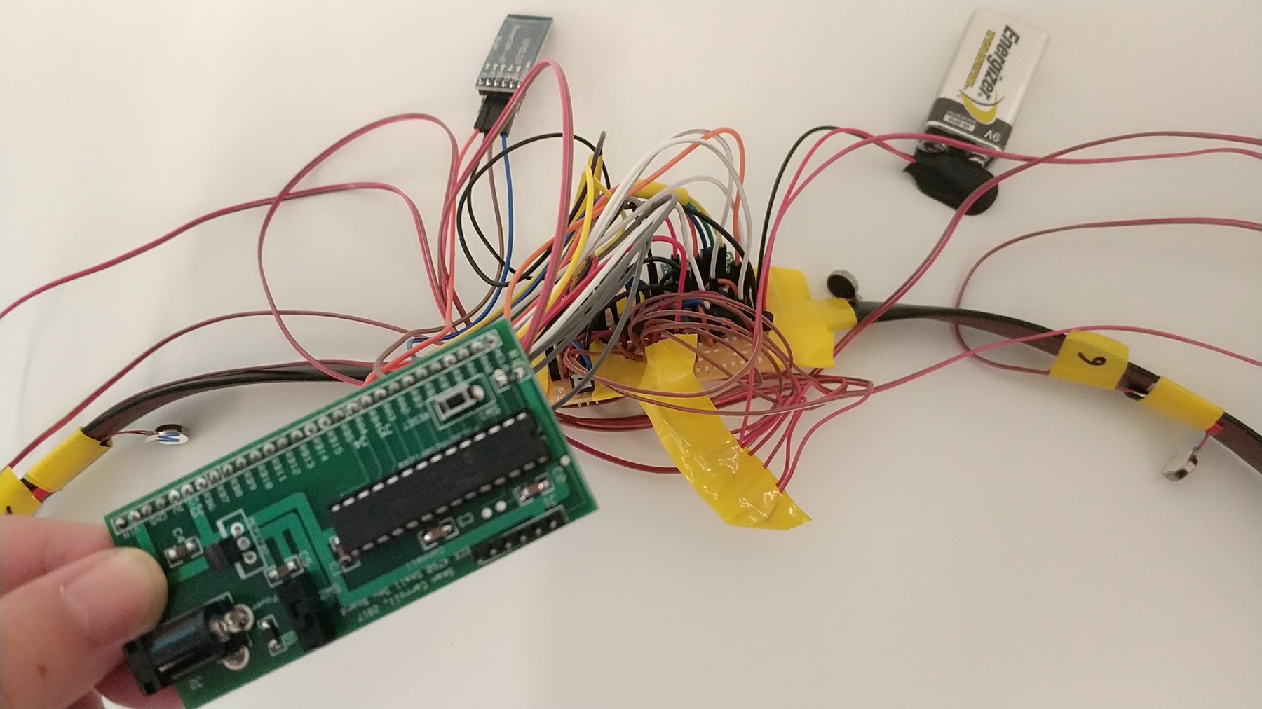
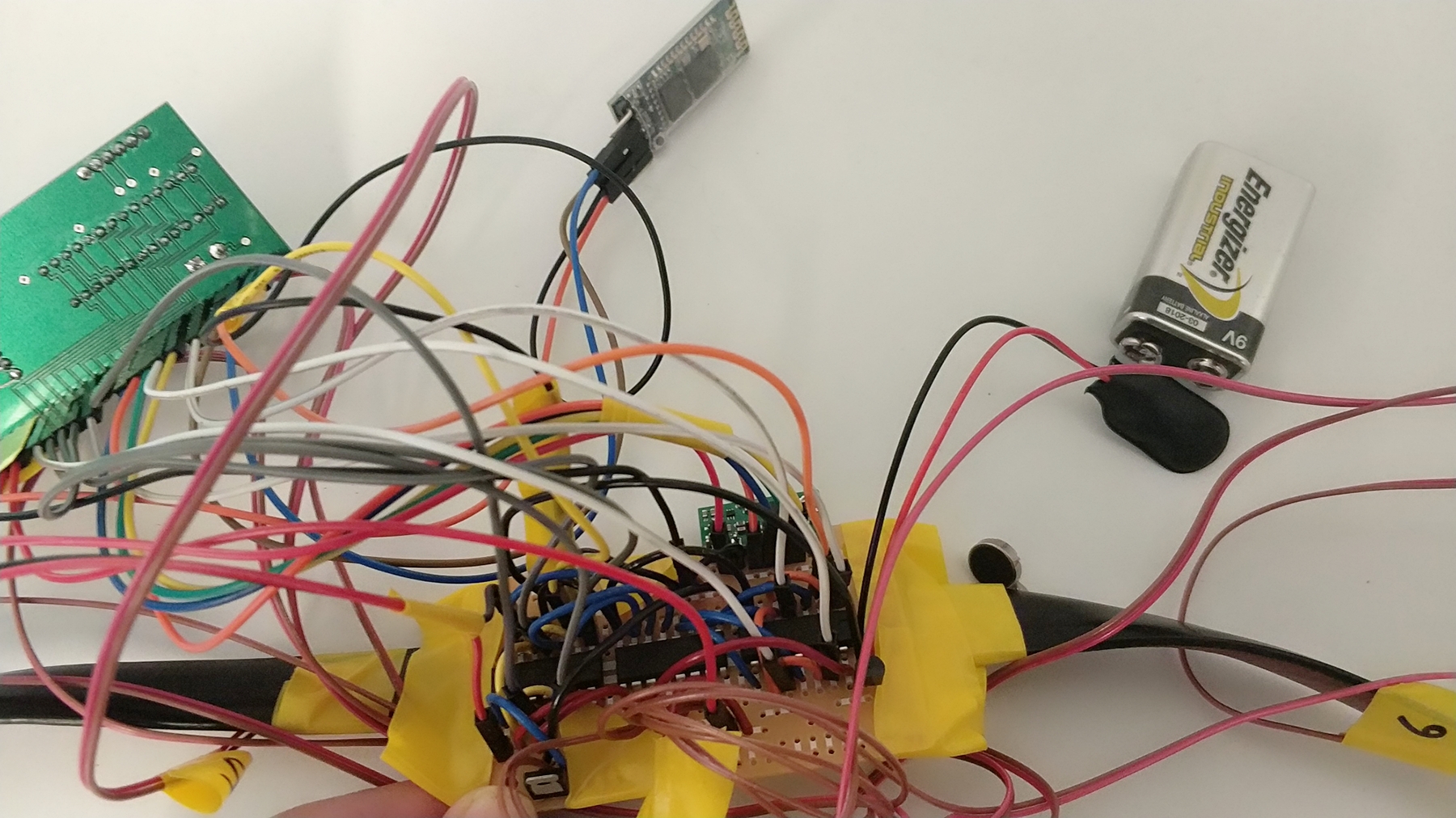 The belt unit came out as a bit more of a mess. We'd originally been planning to use a different belt that would have let us stuff the wires inside of it but it turned out to be very difficult to assemble and we instead opted for the leather belt you can see in our pictures. We ended up with a bit of a rat's nest of exposed wires going everywhere though we did our best to tape things down.
- The motors were individually controllable with varying PWM signals. Based on our user experience testing we were able to come fairly close to achieving our goal of a smoothly interpolated vibration ablge. Although there were some discontinuous jumps as the signal moved around the belt, you could definitely feel it moving in a way much smoother than just jumping from motor to motor
- Frustratingly, we weren't able to get good results from the compass mounted on the belt. We made the simplifying assumption that the module would stay vertical (and attempted to tape it in a position where it would) but in practice it ended up at all sorts of cock-eyed angles. A better solution would have been to do the full tilt compensation using the accelerometer on board but we ran out of time to add it.
How we enforced safety
Since this project involved both electronics and water, there was the ever-present fear of electrocution. However luckily the voltages and currents involved were insufficiently high to run any real risk of damage. People lick 9 volt batteries all the time with little in the way of long lasting consequences. Another safety consideration was whether if the controlling microcontroller fails the vibration motors could go haywire and do any damage to the user. However the tiny little 100 mA motors we were using were too low powered to do any real damage. Even if they were to all fire at full power they would be unable to seriously injure the user - in fact this might even be a desired effect in some cases. Running more power than designed through them would burn them out long before the point at which they became high powered enough to inflict harm.
Interference with other people's designs
When we did research on this project, we encountered microcontroller projects that constructed weathervane and wind speed detector. However, there was no other project that was specifically designed for sailors and built a hepatic feedback device that could reflect the wind direction to the user directly.Human factors usability
This project was intentionally designed to be as usable as possible. By taking advantage of the fine tuned human vibration sense we were able to convert an environmental measurement into a haptic input which with some practice humans would be able to interpret naturally. The user interface borrowed from standard clothing design considerations. There were no special buttons to press or screens to stare at - one must simply put on a belt and feedback begins.
Conclusion
Our Thoughts
Overall, we really enjoyed working on the project and we are proud of how the weathervane turned out. If we had the time to hide the bundles of wires on the belt side nicely, the prototype would look more appealing and user-friendly.
We wish we could have less trouble working with the compass module so that our prototype would deliver more accurate wind readings. The magnetic interference on the weathervane side and the general difficulties on the belt side both forced us to scale back the project. These were all factors we should have considered more carefully when we first chosed materials and design this prototype.
Since we designed our prototype specifically for sailors who had chances to encounter all kinds of weather conditions, proper weatherproofing would also be a critical factor to take into consideration if we want to turn this prototype into a viable product.
Applicable Standards
Our design conformed to all relevant IEEE standards. This was the case since we did not implement any custom bluetooth communications. To stream wind readings from the weathervane to the belt, we used two standard pre-certified HC-05 bluetooth modules, which conformed to all standards set out by the IEEE Bluetooth Special Interest Group (SIG).
IP Considerations
All source code was produced by the members of the group and external packages such as protothread were used with permission from the instructor (Bruce Land). All analog circuit designs and external modules (bluetooth module, hall effect encoder) were adapted from open-sourced, publicly available schematics and therefore require no legal agreements be made with original authors. As a result, our designs would potentially be patented with few to no Intellectual Property conflicts. As we have open-sourced our designs, our work may also be published in any magazine or journal.
Ethical Considerations
Our project was executed with close attention paid to the IEEE Code of Ethics. During our research, planning, design, and execution phases, we held ourselves to high ethical standards which included working to not only ensure our project met all quality technical standards, but also holding ourselves to a professional working standard. We ensured that we constantly interface with other students, TAs and Teaching Assistants with a respectable level of maturity and made an immense effort to work out all technical problems that arose internally within our group. With specific regards to the Code of Ethics, our project is absent of any potential unsafe factors which intentionally endanger the public or environment. As we have open-sourced our designs, we have minimized any potential conflicts of interest and false claims about the technology used. By designing this hapetic feedback weathervane, it has been our intention to improve the senses of sailors on sailing boat by adding useful capabilities that are absent in any current designs. As such, we've strove to make the prototype as viable as possible given the time constraints and available resources. Therefore, throughout our design process we have seeked honest criticism in all forms from our peers and have worked to enhance out own technical compentence in order to unerstand the greater limitations imposed on us by the technology used.
Legal Considerations
Very little of our design is the sort of thing with any particular applicable laws. As already discussed, safety and human factors aren't problematic in this case. The only piece where there are explicit laws covering our usage is the bluetooth transmitter we use to talk between the belt and the weathervane. However since we used an off the shelf HC-05 module which is already certified as complying with relevant regulations, there are no concerns here. The module we chose is designed so that even with invalid inputs, it is impossible for it to violate transmission laws.Appendix
Appendix A - Project Inclusion
- The group approves this report for inclusion on the course website.
- The group approves the video for inclusion on the course youtube channel.
Appendix B - Schematics
Motor Circuit
Bluetooth Module Circuit
Accelerometer and Compass Module Circuit
Hall Effect Sensor Circuit
Hall Effect Position Encoder Circuit
Power Source Circuit
Appendix C - Pinouts
Weathervane
| Pin | Component | Type | Group | Assignment |
|---|---|---|---|---|
| U2TX | Bluetooth Serial | Output | 4 | RB0 |
| U2RX | Bluetooth Serial | Input | 2 | RB1 |
| SEL1 | Motor 1 Enable | Output | ANY | RB11 |
| SEL2 | Motor 2 Enable | Output | ANY | RB3 |
| SEL3 | Motor 3 Enable | Output | ANY | RB4 |
| SEL4 | Motor 4 Enable | Output | ANY | RB7 |
| SEL5 | Motor 5 Enable | Output | ANY | RB8 |
| SEL6 | Motor 6 Enable | Output | ANY | RB9 |
| SEL7 | Motor 7 Enable | Output | ANY | RB10 |
| SEL8 | Motor 8 Enable | Output | ANY | RB13 |
| OC1 | Motor1-4 Amplitude | Output | 1 | RA0 |
| OC2 | Motor5-8 Amplitude | Output | 2 | RA1 |
| SCK2 | Compass SPI | Output | BOUND | RB15 |
| SDO2 | Compass SPI | Output | 2 | RB5 |
| SDI2 | Compass SPI | Input | 3 | RA4 |
| CS | Compass SPI | Output | ANY | RA3 |
Belt
| Pin | Component | Type | Group | Assignment |
|---|---|---|---|---|
| U2TX | Bluetooth Serial | Output | 4 | RB0 |
| U2RX | Bluetooth Serial | Input | 2 | RB1 |
| SCK2 | Compass SPI | Output | BOUND | RB15 |
| SDO2 | Compass SPI | Output | 2 | RB5 |
| SDI2 | Compass SPI | Input | 3 | RA4 |
| CS | Compass SPI | Output | ANY | RB2 |
| IN | Hall Effect Sensor | Input | 3 | RB13 |
| SCK1 | Endoer SPI | Output | BOUND | RB14 |
| SDO1 | Encoder SPI | Output | 2 | RB8 |
| SDI1 | Encoder SPI | Input | 2 | RB11 |
| CS | Encoder SPI | Output | ANY | RB3 |
Appendix D - CAD Files
Here are all of our CAD files for the project:
Appendix E - Cost Details
| Vendor | Part Number | Description | Quantity | Unit Cost($) | Total Cost($) |
|---|---|---|---|---|---|
| ECE Department | PIC32 | MicroController | 2 | 5.00 | 10.00 |
| ECE Department | Small Board | 2 | 4.00 | 8.00 | |
| ECE Department | Headers | 56 | 0.05 | 2.8 | |
| ECE Department | 9 Volt Batteries | 2 | 2 | 4 | |
| ECE Department | Small Solder Board | 2 | 2 | 4 | |
| ECE Department | Jumper Cables | 44 | 0.10 | 4.4 | |
| Adafruit | 1201 | Vibration Motor | 8 | 1.76 | 14.08 |
| Adafruit | 158 | Hall effect Sensor | 1 | 2.00 | 2.00 |
| Adafruit | 9 | Rare Earth Magnet | 2 | 2.50 | 5.00 |
| Agway | 1'' Aluminum pipe | 0.33 | 6.79 | 2.26 | |
| Amazon | HC-05 | Bluetooth Module | 2 | 7.50 | 15.00 |
| McMaster Carr | 6455K88 | Bearings for 1'' Diameter Shaft | 2 | 6.68 | 13.36 |
| McMaster Carr | 6432K25 | 1'' Diameter Shaft Collar | 3 | 2.4 | 7.2 |
| Mouser | 482 | Hall Effect Position Encoder | 1 | 6.44 | 6.44 |
| Robotshop | LSM303D | 3-Axis Accelerometer and Compass | 1 | 7.95 | 7.95 |
| 106.49 | |||||
Appendix F - Work Distribution
We worked closely together throughout the project. We worked on all the soldering, circuit design and programming together in the lab. Reuben created all the CAD models for 3D printing the weathervane. When writing the final report, we splid the parts and worked on different sections of the website through github remotely. Keyi worked on the high level design, hardware design, results, conclusion, appendix, and all the circuit schematics. Reuben worked on the introduction, hardware design, software design, and conclusion.
Appendix G - References
Datasheets
- HC-05 Bluetooth Module
- MLX90316 Rotary Position Sensor
- LSM303D 3-Axis Accelerometer and Compass
- US5881LUA Hall effect sensor
- PIC 32