
A robot that can detect the starting state of any Rubik's Cube and solve it in less than 29 moves.
Shivansh Gupta, sg739 & James Connelly, jpc324
Our project was creating a rubiks cube solving robot that utilized image processing, Kociemba's algorithm, and servos acting as claws/arms to turn the cube. We had a goal of being completely self contained and would not need any human interaction after the initial cube placement. In order to achieve this, we needed a way to take in the input of our initial state of the cube. This required taking pictures of the cube and using an image processing script we wrote using the openCV package in python. This program worked by checking for red, green, blue, orange, white, and yellow and taking an average of the color at each position to figure out which of those it is. After processing the 6 images, our code then passed in the input to our algorithm. We used an algorithm named Kociemba's algorithm. This algorithm works for a solution by breaking up solving the cube into two steps. It is important to note that Kociemba's algorithm doesn't offer the optimal solution, but instead offers a "reasonable" solution that is usually within 25 moves or less. The optimal solution algorithm could take a very long time to run so we opted to go with Kociemba. After we got our list of moves, our plan was to send this over serial to the pic32. The chip then decodes this string and stores the moves in an array to keep track of them. Four claws consisting of two servos that allow the claw to rotate (actually turning the cube) and extend/retract, allowing you to move the claws without moving the cube. Getting the claws to line up correctly took a few tries but after a tremendous amount of calibration, they seemed to be working fine without much human assistance. Here is a video of our robot in action: Rubiks Cube Solver
When we were thinking about what we could do for our final project we started looking up similar projects from other schools. The rubiks cube solver immediately caught our eye as there were a bunch of different ways it was attempted. When we were thinking about how we would attempt it we thought we should use 4 claws that can extend and retract. We also knew we wanted our robot to be completely self contained, so we would need a way to input the initial state of the cube. The easy solution to this would be to use a camera. After some searching around online, we actually found stl files for something very similar to what our plan was on thingiverse. We used their files for the sleeve, arm, claw, and gear.
The next step was deciding on what algorithm our robot would use. Humans commonly solve the cube through a method that solves it level by level. This is not efficient for a robot as it requires a lot of moves despite being very intuitive. We could also use optimal solution solver (referred to as God's Algorithm) although this algorithm can take a very long time to run despite guaranteeing a solution within 20 moves. While doing some research about other rubik cube solvers, we stumbled upon an algorithm called Kociemba's Algorithm. This algorithm doesn't promise the most optimal solution, it promises the most “reasonable”, as the Kociemba algorithm refers to it. This means that it finds a solution quickly that is relatively short (guaranteed to be within 30 moves). The way this algorithm works is in two phases: get the cube into a certain state, then solve the cube from that state. It breaks down the task of solving the cube as a whole in half which allows for easier identification of a solution. The first state is solves to is labeled as G1 =
Gathering the input was the next part of our system. There is an extremely helpful python package named openCV. This offered functionality such as reading a jpeg, checking pixel by pixel, and blacking out any pixel that didn't fit the mask we set. The mask was set to be any range of RGB values of a color on the cube. This will be talked about more in depth in the software design section. We used a webcam to take a photo of each side and then ran out python script on each image. Once the input was collected, we passed that into the kociemba function that returned a string of moves to solve the cube. Finally, our python script utilized a package called pyserial which let us output across a com port on our laptop. As shown in Figure 2, in the appendix, this python script sends our moveset across serial to the pic32. The pic32 then decodes the message sent, stores it in an array, and begins execution of the solution.
The hardware for this project was fairly simple, we used 8 of the circuits from Lab 4 to control the 8 servos we had. These were all soldered onto a small solder board to keep everything organized. This circuit featured an opto isolator that separates the MCU from the servos. The circuit schematic can be found in Figure 1 in Appendix C. We had a single power source connected to all 8 servos. This worked fine as long as only one servo was moving at a time. If you attempted to move multiple at the same time the motors drew more power than the amp could provide and the servos acted erratic and did not do their moves properly. This somewhat limited how we could interact with the cube and caused our movements to be more basic than we could've made them.
The servos used in this project were specifically chosen for their role. The servos in charge of the retracting and extending were slightly cheaper to meet budget. These didn't have to have a tremendous amount of torque after we lubed up the arm and sanded it down to minimize friction. The claw servos had to have more torque. We ordered a servo that has 20 kgcm torque and claimed to offer 180 degrees of rotation. The torque was needed to overcome slight unalignments in the cube, as the claw rotating a face pushed everything back into alignment. The 180 degrees of rotation were need to complete the double turn move needed for our solution. They ultimately proved to not be 180 degrees and more like ~160 degrees and thus our double turn needed to be a 90 degree turn, reset, and then another 90 degree turn. This added a lot of time to our completion time.
The last part of hardware was the structure itself. We needed to have all of the claws line up fairly close together in order to have them perform the moves correctly. We opted to use inexpensive wood and brackets to keep everything in line. We secured two vertical pieces of wood, in which the left and right arms were bolted in, and one across the top connecting them, that the top arm was bolted into. This setup presented numerous issues as it was difficult to keep all of the arms in position while lining everything up for placement. If we learned anything from this project it was that you should spend more money on the actual structural integrity of the robot
The software part of this project, however, was quite complicated, requiring over 1000 lines of code as can be seen in our commented code listing in the Appendix. The first thing we had to do was create the 8 PWM signals to control our servos. All the servos we were using had a pulse width of 20ms with a duty ratio between 0.025 and 0.125 (0.5 to 2.5 ms). Our initial idea was to use the output compare units of the PIC32 to create our PWM signals. Although this method had worked well for us in Lab 4 when the pulse width was just 1ms, we noticed these output compare units were not generating the PWM signals on increasing timer period much further. After some tinkering however, we discovered that we could also increase the pulse width to 20ms by adjusting the timer prescaler, and using this we were able to successfully create the PWM signals we wanted. Unfortunately, as the PIC32 only had five output compare units, we could not use only this method to create all the PWM signals we would needed. To create the rest of the PWM signals, we used an Interrupt Service Routine (ISR) which was triggered by another timer with a period of 0.01ms. In this ISR we used a counter which was incremented on every iteration to set certain pins on the board high or low to manually create the PWM signals we wanted. The counter was reset every 200 iterations of the ISR to give us our 20 msec pulse width.
Once we had properly created and verified all eight of our PWM signals and put together all the moving parts of our robot, we began the arduous and difficult process of calibrating all the servo movements. In order for the claws to retract, extend, and rotate without interfering with each other, they had to be almost perfectly aligned. The PWM signals allowed us to set our claw servo to either vertical or horizontal and our arm servo to either extended or retracted by modifying the duty cycle of the signal. These values were calibrated roughly at first and fine tuned throughout the entire time we were building it. Throughout this entire project we used an incremental design process to program and test all of the functions of the robot. A great example of this is how we developed the moves that the robot had to perform. First we got the most basic moves of the robot (i.e. the extension and rotation of the claws) working and tested. Once we were confident that these moved were working as they should, we combined these basic moves together to form the more complex moves such as setting the claws on the cube in the correct orientation, which in turn constituted the even more complex moves such as rotating the cube and turning each of the faces of the cube. A full list of all the moves we had the robot programmed to do as well as how each move was done can be found in our commented code listing in the appendix below.
Next, we moved onto creating python program that would be running on our computer. This program would be responsible for taking photos of each of the cube's faces using the connected webcam, processing those images to detect the pattern on each face and storing it in the appropriate format, running Kociemba's algorithm on that input, and sending over the solution to the PIC32 through serial.
As mentioned in the high level design section above, most of the image processing was done with the help of an open source computer vision library that is available for Python known as OpenCV. Using this library, we had set up our program so that we would take a picture of each of the cube faces by pressing the ‘Enter’ key whenever the robot presented the appropriate face of the cube. These images, which were saved in the same directory as the python program, were then iterated through and processed using a for loop. For each image, a mask was created for each of the six colors of the Rubik's cube, which were then overlaid on top of each other to give us a virtual representation of the cube's face. Since the camera would be in a fixed position, we knew roughly what parts of the image each of the blocks of the face would be on, so we created a small rectangle on each of the blocks, computed the average color in each of them (ignoring all the black pixels), and compared it against certain pre-defined boundaries for each color to determine the pattern of that face. The rectangles were made slightly smaller than the actual size of the block to account for any small variations in the position of the cube. This process, which can be seen in Figure 3 in the appendix, was then repeated for each of the six faces to form a string representation of the entire cube. Once we had the cube definition string, it was passed into Kociemba's algorithm and the solution string it returned was modified to include a delimiting character and sent to the PIC32 microcontroller using the pyserial library.
Once the PIC32 received the solution string, it was parsed into an array of moves which were finally performed by the robot to solve the Rubik's cube.
The design described in the above sections is how we ideally would have liked our robot to behave. Unfortunately, in reality, we were unable to get our robot to perform as such due to various problems I will now describe. The first problem that we faced was the 3D printing of our components themselves. Our components were designed to slide in and out of each other with the least friction possible, and this was reflected in the dimensions of our components. However, the dimensions of the 3D-printed components we received from the Rapid Prototyping Lab (RPL) here on campus were quite different to what we submitted, which meant that we had to spend a lot of time sanding down the components and had to use some lubrication as well to ensure that they were able to slide in and out of each other easily. However, since this sanding was done by hand, it was impossible to ensure that all of our components were sanded down the same amount and this led to some of the components (such as the servos and the claws) not fitting in their sockets properly, which we had to remedy using screws and super glue.
Another big problem we faced was the calibration of our servo movements. One servo per arm was used to extend and retract the claw and the other servo was used to actually turn the claw. When calibrating the extension/retraction claw, we had to make sure that the retracted claw was far enough away that its movements did not affect the cube and that the extended claw was tight enough to the cube for cube not to slip out of its grip when the bottom claw was retracted. Since our servos only had about 60 degree range of motion, there was only a small range of distances where both of these conditions could be met. In fact, we had to rebuild our entire support structure for the arms a couple of times before we were satisfied with the locations and orientations of the arms.
Then we have the claw-turning servos. While testing them we discovered that although the servos had claimed 180-degree rotation when we purchased them, in reality they only had about a 160-degree range of motion. This was especially annoying since it meant that were unable to rotate a face of the cube 180 degrees without retracting and resetting the claw, which really decreased the performance of our robot. We also had to calibrate the claw-turning servos to make clean and complete turns a majority of the time. This was especially difficult as, although it seemed that our claws were calibrated properly when we were testing the contraption with no cube in it, as soon as we added the cube in the claws would lose their calibration. After some experimentation, we discovered that the same PWM duty cycle would set the claws to two different angles depending on whether it was under load or not. Once we realized this we were able to calibrate the claw-turning servos a little better but there was still a fair bit of randomness to the accuracy of the moves.
Despite all of these difficulties, we felt that we had got the robot calibrated quite well towards the latter stages of our project, but unfortunately, about 30 mins before our demo was scheduled, an improperly commented block of code caused our timing to mess up and one claw decapitated another. As we hurried to fix the claw before our demo, we did not have the time to properly calibrate it so we had to perform our demonstration with relatively untuned calibrations, which meant that we had to interfere with the correct working of the robot a lot more than we would have liked.
We also faced quite a few issues with the image processing software that we had designed, in particular, while calibrating the RGB ranges for each color. We had initially thought that the program would have some difficulty differentiating between yellow and white since those colors looked quite similar on the images captures, but to our surprise it was able to differentiate between those colors perfectly. Where we did encounter some trouble was the program being able to differentiate between orange, yellow, and red. Although in most cases it was able to tell these colors apart, whenever there was an orange block in the upper-row of the cube, there was significant glare on the block from the overhead lights which caused the program to interpret that color as yellow. We tried playing around with the RGB boundaries for each color but the RGB value of yellow and orange-with-glare were almost identical. We then tried to block out the overhead lights with a piece of cardboard, but then we found that the program was having difficulty differentiating between orange and red, and once again the RGB values of these colors were practically identical. We tweaked these RGB limits as much as we could to try and get the most consistent results, but we were unable to reach 100% accuracy giving the problems mentioned above. Therefore, we had to always keep an eye on the robot to make sure it was detecting the proper colors and intervene to manually fix the colors whenever we noticed it had made a mistake.
Finally, we were not able to get the serial communication between our computer program on python and the PIC32 working as we had planned. We were stuck on this issue for a long time as we thought that we had all the code for the serial communication written correctly on the PIC32 side and we also had prior experience with the python serial library we used so we were pretty sure that everything was working fine on that end. We even probed the UART cables with the oscilloscope to make sure that appropriate signals were being send through it. As we got closer to the time of the demo, due to the unfortunate circumstances mentioned above, we were unable to devote any more time to the correct working of serial and abandoned that part of the project, opting instead to manually transfer the solution generated by the python program to the PIC32 one. During the demo, however, we were informed by the professor that the cable we were using for our USB to UART connection was actually a 5V cable not a 3.3V one, which meant that we had probable fried the two UART pins on the PIC32 that we had been sending our serial data to and this was why our serial wasn't working even though all of our code for the serial communication was correct.
Our design did not meet all of our expectations and can be narrowed down to 3 issues. First off, we could not come up with a reliable solution to prevent glare. We tried keeping the cube in darkness, adding light at more prefered angles, etc but the image processing script consistently mixed up orange, red, and yellow. Perhaps if we were to try this again we could change orange to say bright pink with electrical tape or something of that nature or buy a higher resolution camera, as the one we were using was frequently blurry at the close range we were taking the photos at. Another issue was completing the serial communication between our python script and our board. This issue was due to using an old 5V serial cable that we found in the lab instead of a new one. We believe that this caused the pins we were using for serial communication to blow without us even noticing. Despite seemingly having all the basic serial communication code present, this issue was brought to our attention during our demo so we didn't have time after the fact to check if this was indeed the reason. The final problem was the actual movements of the servos themselves. They occasionally needed human assistance as they turned inconsistently when moving the cube. If we had more time to work on this we would have calibrated a "load bearing" version of horizontal and vertical and seen if that would have moved better. Another option would have been to use metal instead of 3D printed parts with wood. This would offer much more precision and accuracy with our claw locations and movements.
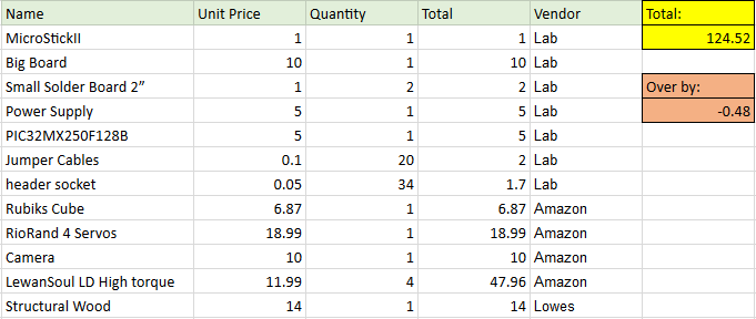
Our cube took roughly 4 to 5 minutes to complete a cube solution which is fairly comparable to a beginner cube solver. A significant portion of that was due to the delays we had to set to allow for potential human involvement if the cube became misaligned. If we could get rid of the need for that delay with more consistent movements, we believe we could've roughly halved our time to completion. The fastest recorded time by a human for solving a 3x3x3 cube is 4.22 seconds by Felix Zemdegs. The fastest robot to solve a cube was built by a German named Alfred Beer and completed the solution in a mere .637 seconds! As mentioned earlier, we 3D printed parts from thingiverse, we used python packages pyserial and openCV, and used a python implementation of Kociemba's algorithm. The links to all of these can be found in the appendix as well as in the high level design section. Our project also followed the IEEE Code of Ethics. Since our robot only interacted with itself and did not move, it did not pose any significant risks to the environment or the welfare of the public. There were no conflict of interests as we were not creating this for any reason other than self interest. All of our data is honest and our videos prove functionality. We did not accept any bribes while working on this project. We were qualified enough to attempt this project and it was extremely academically stimulating. We have listed all the work that we used that we did not personally create and have offered criticism of our own work and possible improvements. All members and other groups were treated fairly and no acts of discrimination took place. Our work did not look to injure anyone, destroy anyone else's work, or damage their reputation. We attempted to help other groups to the best of our ability, even offering extra parts to another group. Finally, there were no safety concerns with this project and no legal considerations for a rubiks cube solving robot.
Although ideally our robot would have been able to run without any human interference at all, due to all of the problems mentioned above, our final robot actually required quite significant human interference in order to work properly, and as such was not very usable by someone who did not already have a somewhat decent understanding of how the robot worked and what to look out for. In terms of safety constraints, our robot did not pose any particular danger to its user so there was really no need for any safety constraints. However, we did include a slightly longer delay between each move than necessary in order to give the user enough time to interfere if they saw that the robot was not behaving correctly. And finally, the only interference our robot had with other people's designs was the fairly loud sound of the servos moving.
The group approves this report for inclusion on the course website.
The group approves the video for inclusion on the course youtube channel.
Rubiks_PC.py - Python program for image processing and cube solving
Rubiks_PIC32.c - Main program file
Figure 1: Schmatic of Servo Circuit
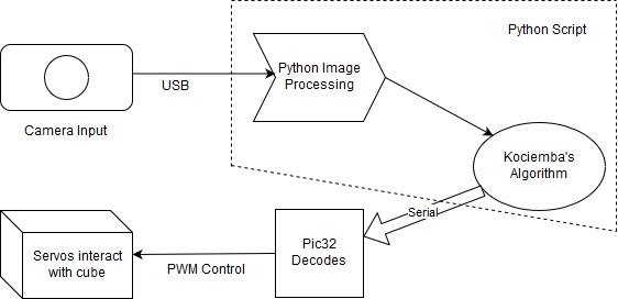
Figure 2: Block Diagram of System
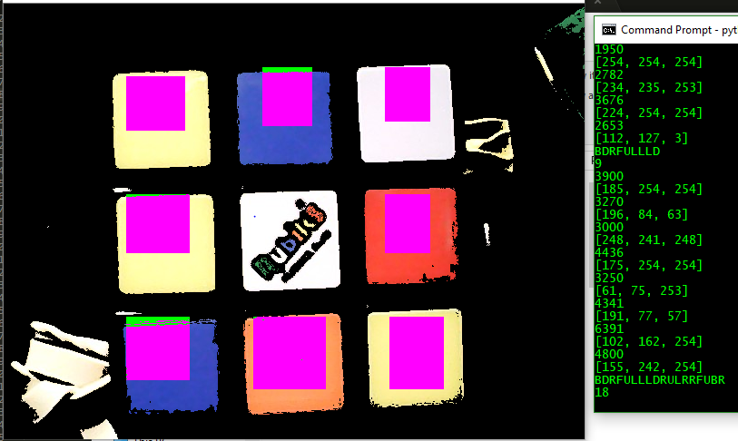
Figure 3: Image Processing Program
PWM Creation and Control
Serial Communication
Building the structure
Calibration
Image Processing with OpenCV
Final Report: Software Design, Results, Website
High level movement functions
Soldered the PWM circuits
Building the structure
Calibration
Image Processing with OpenCV
Final Report: Introduction, High Level Design, Hardware Design, Conclusion
Kociemba: https://github.com/muodov/kociemba
Open CV: https://pypi.org/project/opencv-python/
PIC32 Peripheral Libraries for MPLAB C32 Compiler: http://ww1.microchip.com/downloads/en/DeviceDoc/32bitPeripheralLibraryGuide.pdf
LewanSoul LD-20MG Servo Datasheet: http://www.lewansoul.com/product/detail-18.html
RioRand MG-995 Servo Datasheet: https://www.electronicoscaldas.com/datasheet/MG995_Tower-Pro.pdf
PIC32MX250F128B Datasheet: http://www.microchip.com/wwwproducts/en/PIC32MX250F128B
PIC32 hardware manual sections: http://people.ece.cornell.edu/land/courses/ece4760/PIC32/index_Ref_Man.html
Kociemba's Algorithm: http://kociemba.org/cube.htm
Rubik's Cube World Record Build: http://www.guinnessworldrecords.com/world-records/fastest-robot-to-solve-a-rubiks-cube