ECE 4760 Project: Kendo Sword Trainer
Iman Nandi and Weichen Zhou
Introduction
For our final project, we built a system to aid in practicing kendo sword strikes by providing feedback to a kendo practitioner for improving their form. A set of three piezoelectric sensors on a helmet were used to detect the location and strength of the strike. Thus, the set of piezoelectric sensors would help find the strikable area, which is hard to find by human eyes, but that alone can not decide whether a strike is good. An LSM9DS1 integrated circuit (IC) device possessing a 3-axis gyroscope and 3-axis accelerometer was attached to the kendo sword to sample the direction of the sword during a strike attempt using a combination of the two sensors’ feedback. A strike attempt is identified and started by the gravitational force that the LSM9DS1’s accelerometer reading is used to calculate, which ensures that a strike has the required strength to be considered a viable strike. Combining the direction and hitting area of the strike, we evaluated whether or not a sword strike hit the helmet and how well a sword strike was executed on a scoring scale of 0-5. A visual design of the score along with relevant statistics and graphics was outputted to the TFT LCD display.
High Level Design
Rationale for Project Idea:
Kendo is a Japanese style of fencing that uses a bamboo sword called a shinai. This martial art is not only a practice of physical form, but also a training of spirit. As a “way of sword”, it teaches people how to be sharp and decisive, just as a sword would cut through its enemy. For beginners, however, practice with the right form is an important step to realize the spiritual meaning behind this martial art. In kendo, the will to “cut through” is important for strikes. That is, you are not just hitting your target with a stick but rather intending to cut through it with your sword. From a physical perspective, that means the strike needs to be swift, precise, and straight in movement during the swing. In addition, only specific areas are considered valid targets for strikes. On the head, there are striking areas known as men, sayu-men, and yoko-men, which are the upper, left, and right side of the head. From this background, two aspects of hardware were designed to pick up signals and feedback that can be used to decide how correct a strike is: piezoelectric sensors and a combination of a gyroscope and accelerometer acting as a direction sensor. These sensors are shown with the full high level design setup in Figure 1 below:
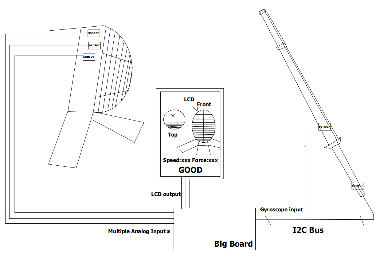
Figure 1: High Level Design
Background Math:
Using trilateration, by knowing the location of three points x1, x2, and x3, as well as their relative distance to a fourth point x4, we can get the location of x4 by finding the intersection of the three circles centered at x1, x2, and x3 with radius r1, r2, and r3 respectively. This is depicted in Figure 2 below:
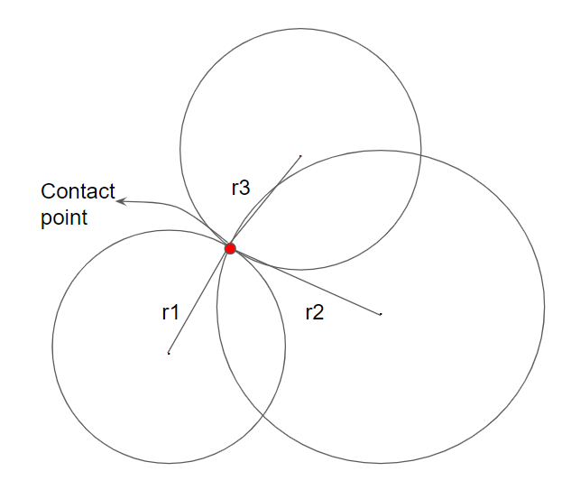
Figure 2: Trilation Point Estimation
By setting two points on the x-axis (0,0) and (0,U), we can get the two points’ potential destination at (x,y) such that the following holds:
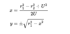
Calculating the distance to the third point will eliminate a wrong point, leaving us with the desired contact point. However, with our ADC scanning setup, we couldn’t make a precise decision on the contact point. Instead, we give a rating on left/right/center based on the information we gathered.
Details of the direction calculation based on the gyroscope and accelerometer from the LSM9DS1 is discussed in the Software Design section.
Logical Structure:
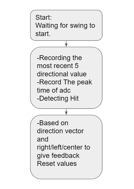
Figure 3: Logical Structure of Design
Hardware Design
The hardware used in this project includes the following:
- 1 LSM9DS1-9 DOF Sensor
- 3 Piezoelectric Sensors
- 3 Filter Circuits consisting of:
- 4-MΩ Resistor
- 1-pF Capacitor
- Diode (1N4001)
- Buffer (MCP6242)
LSM9DS1:
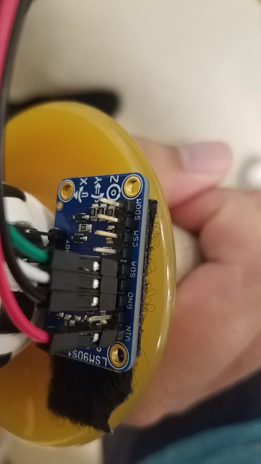
We used the LMS9DS1 gyroscope and accelerometer sensors to detect the direction of the swing. The LMS9DS1 is attached on the kendo sword with velcro. This chip has 9 outputs, which include the angular speed, acceleration of direction, and magnetic field for the x, y, and z axes of motion. For our project, we only used the angular speed and acceleration information from the gyroscope and accelerometer respectively.
This chip can use both SPI and I2C communication. After doing a little research, we were able to find an I2C library for this chip. Thus, we decided to use I2C communication for our project to accelerate progress. We used the I2C1 peripheral on the PIC32 to connect to the I2C port on the LSM9DS1 chip, as shown in Figure 4 below:
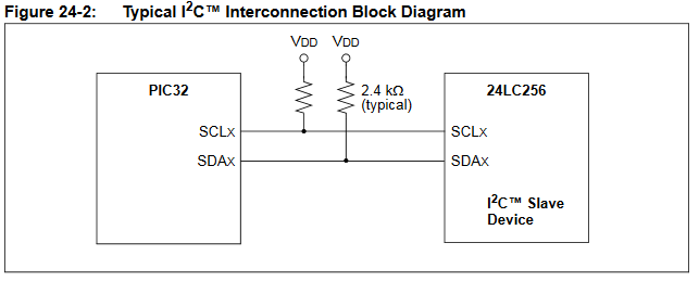
Figure 4: I2C Connection Diagram
A total of 4 wires are connected between the Big Board with the PIC32 and the LSM9DS1: RB9(SDA1)/SDA, RB8(SCL1)/SCL, 5V/Vin, GND/Gnd. The I2C communication works using a read/write register on the slave device. In our case, a signal from the PIC32 was sent to initiate the communication with the LSM9DS1, and the LSM9DS1 responded with 9 pieces of output data. We modified two parts of the control register shown in Figure 5 to fit our whole project.

Figure 5: LSM9DS1 CTRL_REG1_G Register Bits
We modified the CTRL_REG1_G register to change the output data rate to 119 samples/sec and the internal cutoff frequency of the LSM9DS1 reading to 31 Hz using Table 47 of the LSM9DS1 datasheet shown in Figure 6 below. This is because we wanted to have ADC sampling running at the highest frequency possible.
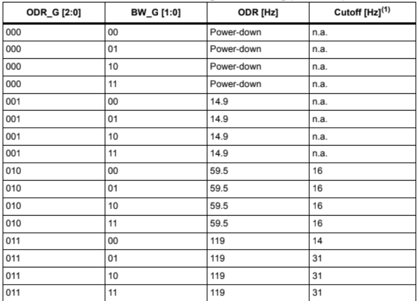
Figure 6: LSM9DS1 CTRL_REG1_G Register Operation Modes
Piezoelectric Sensor:
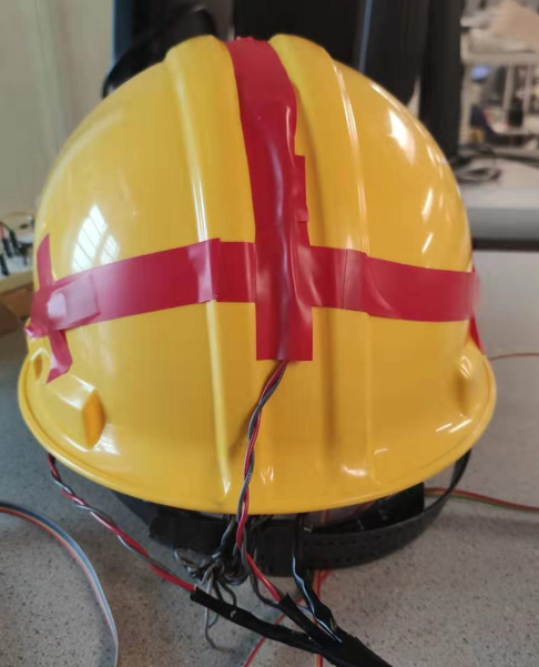
We used three piezoelectric sensors attached to a hard helmet to estimate the hit location of the sword strike. The sensor itself, when bent by vibration, outputs a pulse signal that has a range of roughly ±5V. Before attaching the piezoelectric sensor to ADC ports of the PIC32, we first wanted to modify the piezoelectric signal for better detection. Without a filter circuit, the signal response appeared to be in both the positive and negative direction. To achieve an easier detection of the piezoelectric signal, we eliminated the negative part of the signal.
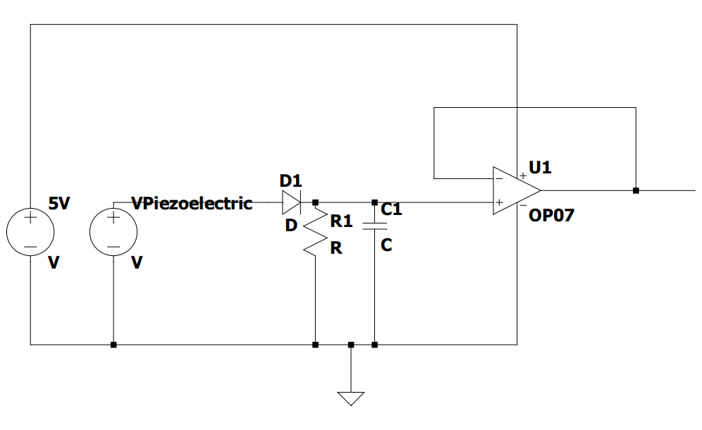
Figure 7: Voltage Clamper and Low-Pass Filter
The circuit in Figure 7 above is what we used to eliminate and prolong the signal (R = 4MΩ, C = 1 pF). The diode only allows current to its right, which eliminate the negative part of the signal. At the same time, the RC circuit on the right has a very low pole frequency, which slows down the decrease of the signal. With this setup, we can prolong the signal. After the signal is processed, we use a buffer to pass the signal to the ADC reading port. The piezoelectric sensor has a very large output resistance. Even with the RC circuits in the middle, the output resistance is still too large to be directly read by the ADC, so we built a buffer with the MCP642 dual operational amplifier to get rid of the large output resistance.
From our research, the speed of a vibration traveling through a hard object is roughly 4500 m/s. The PIC32MX supports ADC sampling at a rate of up to 500 kHz. With three ADC readings, we estimated the sample rate to be 150 kHz. Thus:
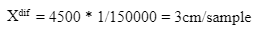
So, if we scan the ADC port at the highest frequency, the vibration will travel approximately 3 cm between each sample. With that information, we can determine the hit point of each strike.
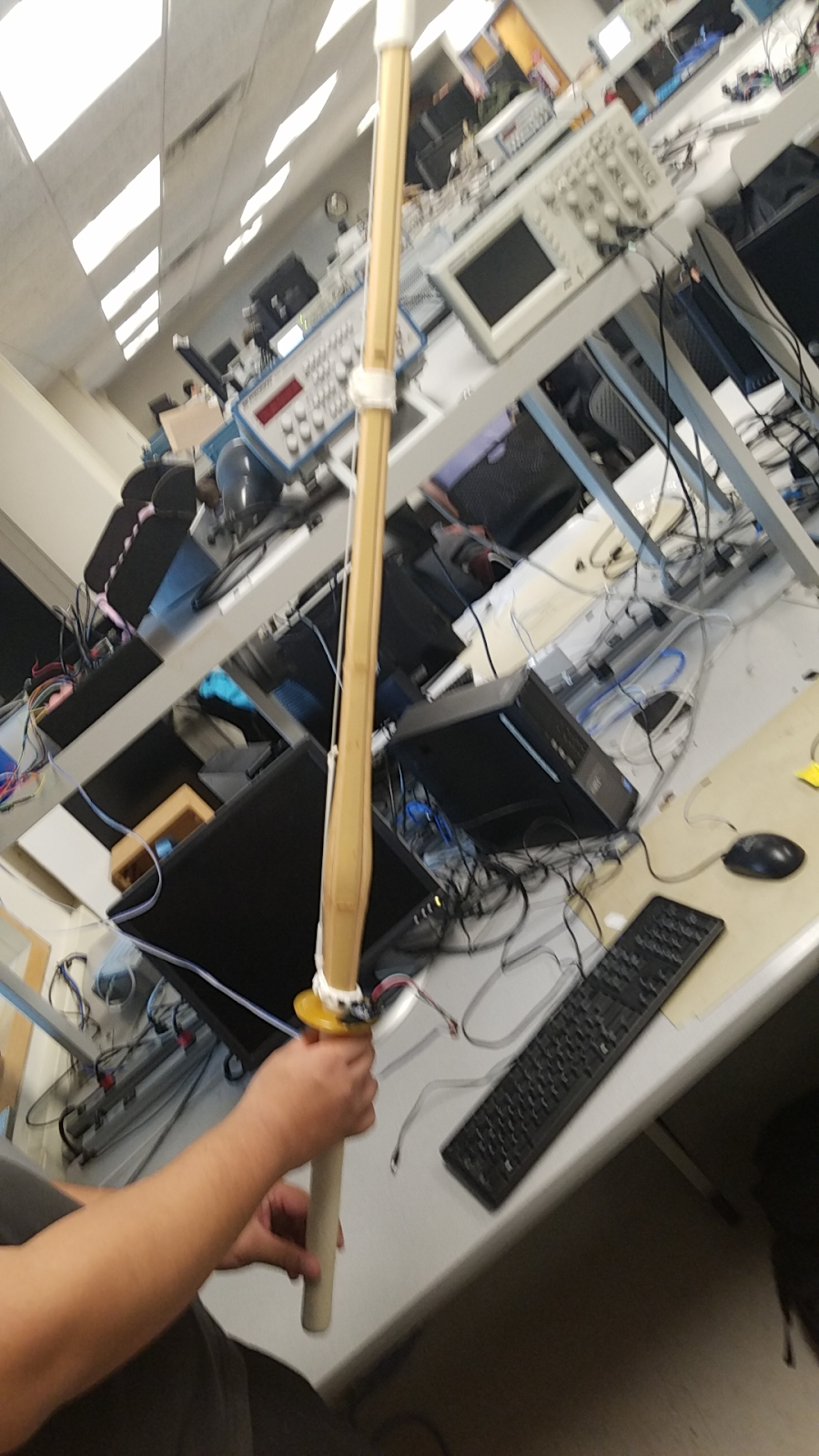
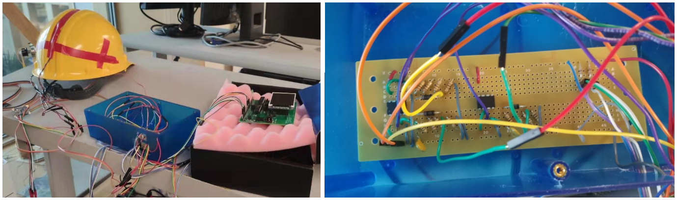
You can view the full hardware schematic in Figure 8 below or in a larger format in Appendix C. Pictures can also be found below for the Kendo sword with a closer look at how the LSM9DS1 device is attached, as well as the helmet setup with a closer look at what the piezoelectric sensor electric taped to it looks like.
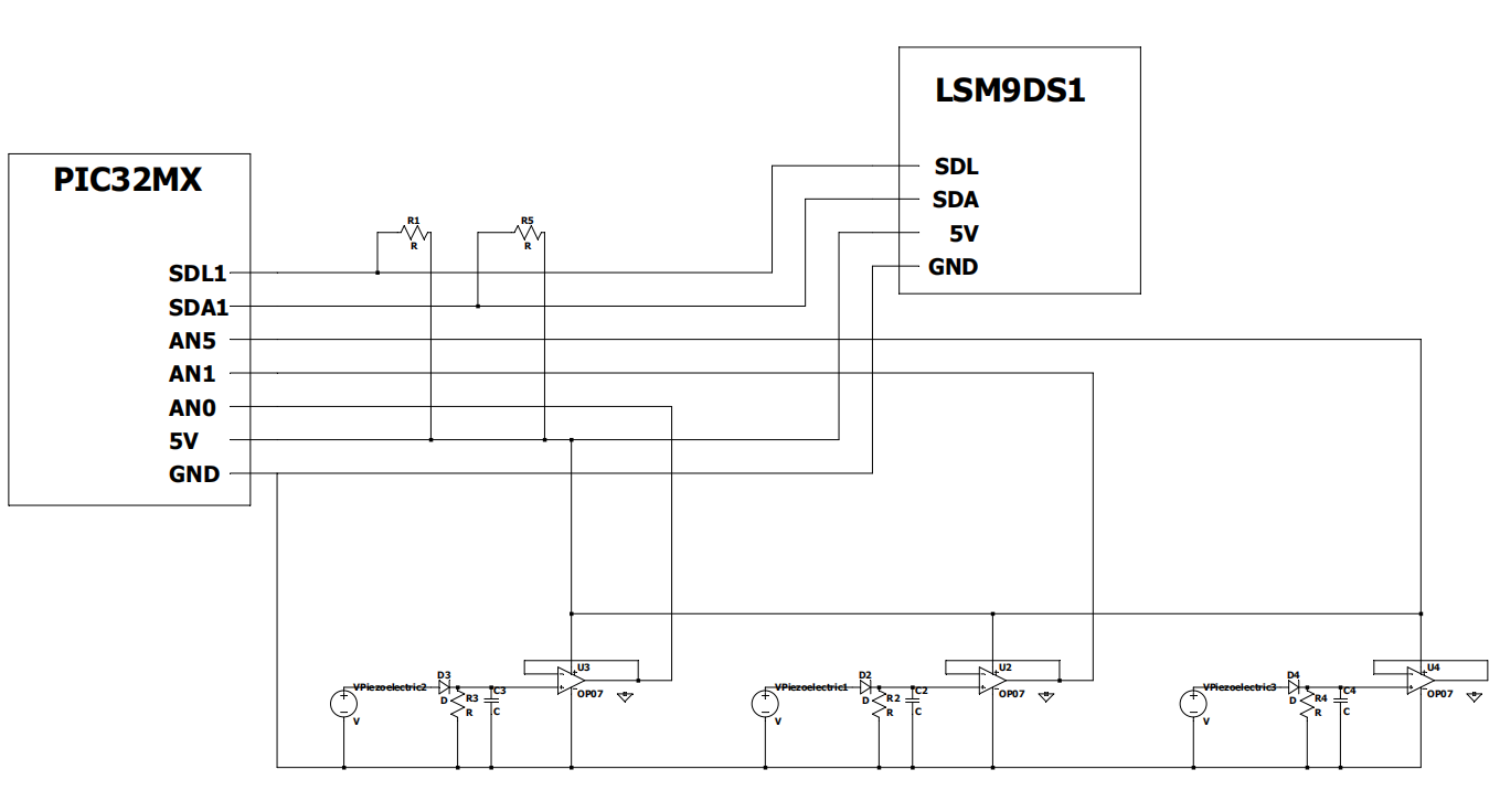
Figure 8: Complete Project Schematic
Software Design
User Interface:
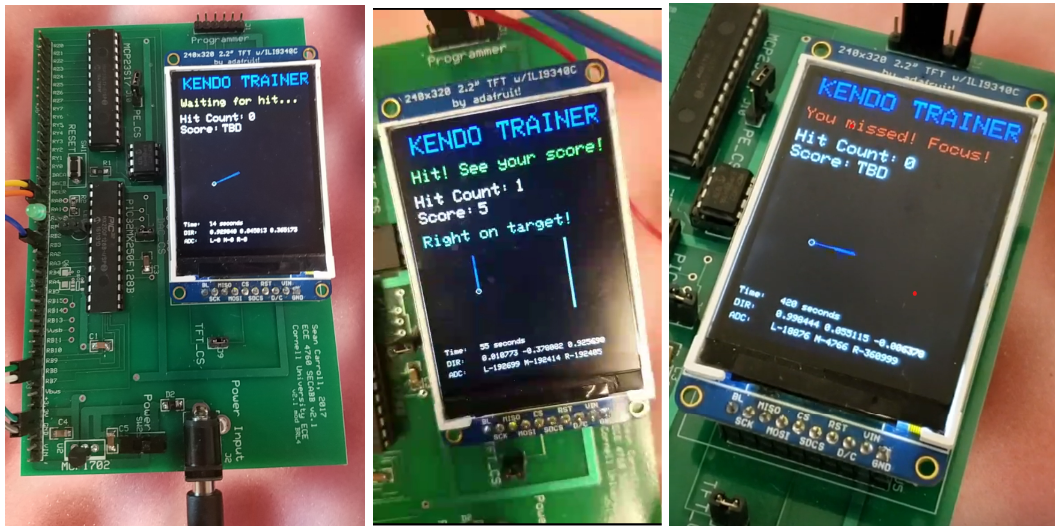
For a kendo trainer, our user interface is designed to naturally detect a strike and give feedback on the result of the swing. You can view the final user interface in the Results section.
At the beginning, the TFT screen shows a waiting message and displays a “side view” of the sword based on gathered direction value. When a strike happens, a huge change in the accelerometer will be detected. Upon detection, a red "flash" will display on the screen, to mimic the motion of the swing. At the same time, the system starts to record a set of 5 direction vectors, which are used later to decide the score of the sword strike. After entering this stage, a hit on the hard helmet (adc_reading > threshold) will cause the system to enter the next stage, causing the recording of direction value to stop. More CPU power is then dedicated to ADC peak detection. The screen will enter the hit stage, and a score will be calculated based on the 5 direction vectors’ values that were measured during the swing. Then, a counter is set in the ADC thread that increases with each sample taken, and an adc_counterX value will be set based on a general sample counter used to track when a peak is detected or updated, where X is each of the ADC channels used, namely 0, 1, and 5.
With all the information gathered, we start to calculate the score. The score has a range of 0 to 5. If a hit left/right is detected, the score is limited to 0-2. If you hit the center, your rating is either 3, 4 or 5. We use the recorded direction vectors to further differentiate the scores. In our case, the most important part of the direction vectors was Ry, which indicates whether the sword is straight or not. Thus, we set our criteria to be based on how many of the 5 direction samples have a Ry value smaller than a threshold. In our case, the threshold was 0.3 for a normalized R. Figure 9 below shows the scoring criteria source code:
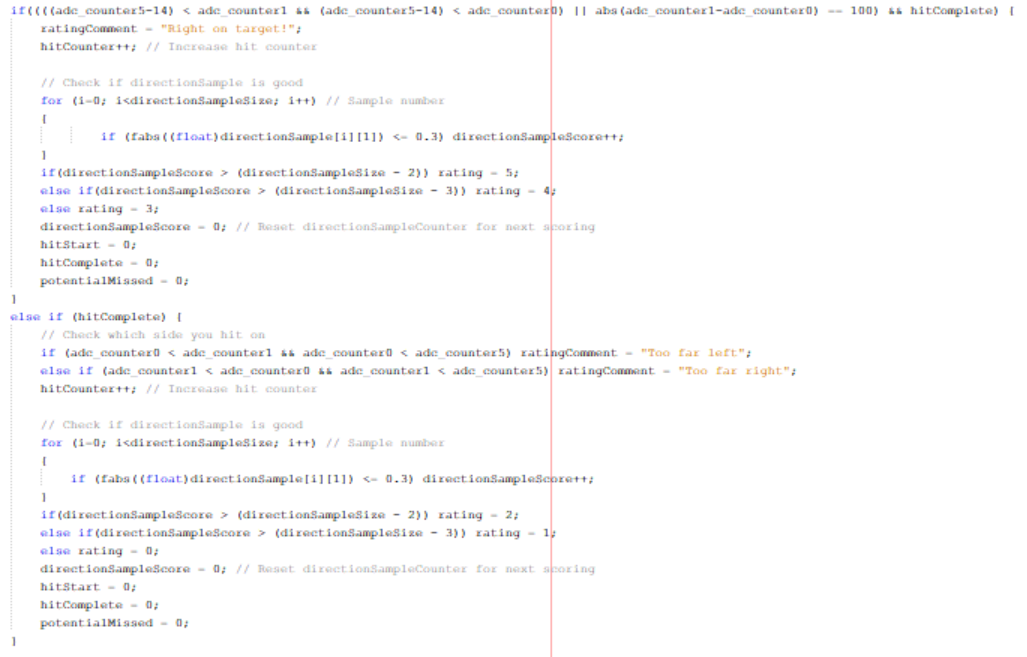
Figure 9: Source Code for Scoring Criteria
The TFT LCD screen then displays the score, a graphical representation of the left/right/center information, and feedback like “Hit! See your score below!” or “Missed! Focus!”. The system will then go back to the idle stage while resetting all the value we gathered for the previous swing. See Figure 10 below for the complete state diagram:
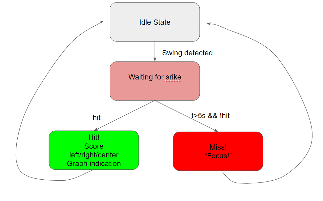
Figure 10: TFT LCD User Interface State Diagram
ADC Reading Logic:
To capture the hit area of a sword strike, an ADC thread is created to read the ADC value. As described earlier, our goal is to compare the time difference of the vibration’s arrival to each piezoelectric sensor. At first, we tried to set up a threshold to record the arrival time of each of the signal. However, we noticed that because the amplitude of each signal was not the same, using amplitude threshold could not precisely capture the difference between the time of arrival of two signals.
Instead, we decided to capture the peak of the signals received. An adc_max value is initiated and reset to zero when the system goes to ideal state. Each ADC value is compared with the adc_max and causes the adc_max to update if the captured value is larger than the old maximum, with a “timestamp” recorded when the peak happened. We were able to improve the detection of hit points after this software implementation change, which is shown in Figure 11 below.
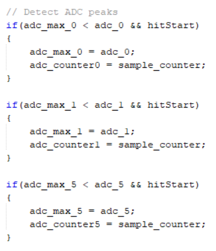
Figure 11: Source Code for ADC Reading Logic
Ideally we would like to compute the exact point of contact with three piezoelectric sensors, but with the direction computation taking lots of CPU resources, our ADC sample rate could potentially have intervals that are not recording value appropriately. At the same time, with noise in the circuit, sometimes the timestamp of a “peak” can be inaccurate. Thus, we decided to instead just show whether a hit with the sword was made at the left, right or center of the helmet. In retrospect, it would have been better if we used a separate PIC32 to solely capture the ADC value, or used other methods for capture.
Direction Computation with Gyroscope and Accelerometer:
For the LSM9DS1 to communicate with the PIC32, the LSM9DS1 datasheet shown in the References section must be carefully examined to be able to implement the required communication code successfully. While we did utilize the datasheet to improve the LSM9DS1’s performance as discussed in the Hardware Design section, this part of the source code was primarily based off of an open-source library for I2C communication specifically between the PIC32 and LSM9DS1, which is referenced in the References section and referred to in our C source code as an include. More time could be allocated this way on software design for the application of kendo training.
An LSM9DS1 thread is dedicated primarily to reading the gyroscope and accelerometer values from the LSM9DS1 and computing with both readings a combined direction vector at a 20-ms interval, which is derived from the output data rate of the chip being set at 119 samples/s. The acceleration reading, because of the presence of gravitational force, is a good indication of direction when the gyroscope is still. When the gyroscope is moving, in our case, when swinging the sword, the force applied on the sword causes the direction reading using only acceleration to be off. At the same time, during motion, the gyroscope’s reading of angular velocity is a good indication of how the direction has changed. Thus, we needed to combine the gyroscope and accelerometer reading together to reconstruct the direction information more accurately. Initially, we tried to average samples of just the gyroscope readings to determine motion, and this was found to not be viable quickly after some testing and research.
To combine the angular velocity and acceleration value, we needed to calculate the direction using the acceleration reading while applying the change shown by gyroscope angular velocity reading.
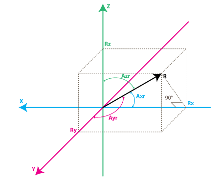
Figure 12: LSM9DS1 Accelerometer Axes of Motion
(Reference: http://www.starlino.com/imu_guide.html)
With the acceleration reading (ax, ay, az), we can reconstruct a vector R, as shown in Figure 12 above, which represents gravity if the gyroscope is not moving. After normalizing the acceleration vector Ra, we can calculate three angles Azr, Axr and Ayr by applying the trigonometric formula below (corresponding variables replaced as needed):
With Axr, Ayr, and Azr calculated, we can apply the gyroscope reading to the direction calculation.
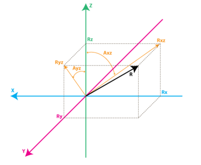
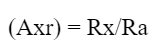
Figure 13: LSM9DS1 Gyroscope Axes of Motion
(Reference: http://www.starlino.com/imu_guide.html)
As shown in Figure 13 above, the gyroscope reading is rate of change of the three angles mentioned. Thus, by applying the gyroscope reading to Axr, Ayr, and Azr and reconstructing the normalized vector Rg, we can get a prediction of R.
After getting the two vectors Ra and Rg, we needed one last formula to decide the actual direction vector. Since Ra is right when the gyroscope is still, where Rg is right when the gyroscope is moving, we make a combined guess

where values from 5-20 for wGyro, representing how much the gyroscope is weighted into the direction calculation, can give a viable result. In the end, we decided to choose the value 10 through testing of what value seemed to provide accurate direction sensing. The direction calculation implementation has a lot of guidance from a guide on Starlino Electronics that is linked in the References section.
With all the calculations needed for the direction calculation, we worried about whether or not we could keep the ADC sample rate high enough to detect a difference in sword strike area. Starting with floating type values for direction calculation, we found that the system stopped working as expected because of the delay caused by the arithmetic calculation. We then decided to switch to _Accum type that provides fixed point computation, which saved us a lot of CPU power. After switching to _Accum, the system went from staggering to having an ADC detection with almost the same accuracy as before the direction calculation’s algorithm was implemented. You can see our software implementation for the direction calculation in Figure 14 below:
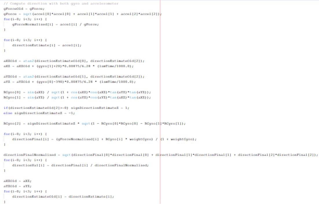
Figure 14: Source Code for Direction Calculation
Design Results
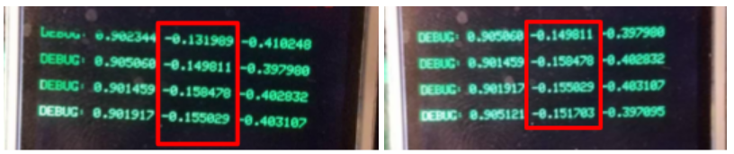
For the hit point detection, our results were mixed. We figured out with a special way of hitting that the system had a fairly good detection accuracy, where the hit area detected was almost always correct. With a normal swing, we did a 20-swing test towards the right side of the helmet, where 16 of the test trials had a correct detection of right or center as expected depending on how close to the center each strike was. The other 4 test trials gave us the opposite detection of left from what was expected. From this level of accuracy and our experience with testing our direction calculation with the TFT as shown below, we found that the LSM9DS1 was performing to our expectations and that other aspects of our design were contributors to inaccuracy in scoring sword strikes. You can also find our final TFT LCD user interface below as well, which proved to be very responsive as we expected during demonstration.
We figured there were two aspects to our design that hindered our accuracy. First, the ADC thread was not always running in our software implementation with threading, making multiple tasks going on in our software execution pose a continuity issue for the ADC detection due to the time used for direction calculation in a separate thread. If we were to continue this project, a separate PIC32 or a better recording method would improve the hit point detection, and we could proceed to implementing the triangulation method described in our High Level Design section that we originally planned to use.
With the piezoelectric sensors, the wires connecting to the sensors had issues at the beginning. When the sensor had a large resistance, a movement of the connecting wire could potentially cause a large signal shift in the ADC reading. We solved this by intertwining the wires such that they spun around each other, as well as electric taping wires in necessary areas to improve wire management and overall safety of the project. This solution reduced the effect, but this artifact still happens when someone approach the helmet. A better solution would be to add a resistor between the + and - connector pins of the piezoelectric sensor. However, with the large internal resistance, this method reduced the ADC signal. In the end, we decided the wire management had compressed this problem to an acceptable level and that we were willing to keep this artifact in of our design as a tradeoff for not allowing our analog signal range to be sacrificed. Our final project setup is shown below with the final signal response filter circuit soldered and packaged in a blue container.
In general, the project was very useable as shown by our demonstration video on YouTube, which you can see below!
Conclusion
Based on our results, we were able to successfully meet several of the essential sensing capability goals that were set at the start of the project for helping a kendo practitioner train using relevant sensors and a microcontroller, as well as create a display interface that adequately scored sword strikes based on our two sensing parameters that were developed. In general, we were able to follow the schedule that we initially planned, but allocating more time towards the end for performance operation and software debugging would have made the process even smoother.
While our software implementation for determining which side of the helmet was struck was fairly consistent, it sometimes could not identify the correct side of the helmet if the sword strike was not close enough to the piezoelectric sensor corresponding to a particular side. Putting more time into understanding the properties of the vibrations when striking the helmet would have helped us improve our software logic to improve our strike area identification accuracy. Potentially, more piezoelectric sensors could be used to collect more ADC data if needed. In terms of direction sampling, our scoring criteria could take into account more requirements of the strike than just being straight on the y-axis of direction, which could have been determined with more research on what makes for a good sword strike given more time. Capturing the force of the sword strike could have been an additional parameter to consider for our scoring system using the LSM9DS1 accelerometer. In this application, the criteria is that it can be neither too weak nor too strong. A heavy blow that doesn’t “cut through” as intended in Kendo can ruin the sword. Capturing voice using a microphone could have been yet another parameter to consider for helping kendo practitioners train since it is common to use a shout known as a kiai to express fighting spirit when striking, which could be evaluated for accuracy.
Ethical Considerations:
Based on the IEEE Code of Ethics on the IEEE website, we followed the 10 stated ethics rules mentioned throughout the project to the best of our knowledge. As rule 3 reinforces in regards to honesty with available data, we made sure to explain where all our relevant sources of information in this project came from to give credit where it is due, as well as critically analyze any shortcomings of the project at its completion regardless of how well it was demonstrated.
Intellectual Property Considerations:
To gear the project’s time towards figuring out how to utilize the LSM9DS1 for determining the quality of a Kendo practitioner’s sword strike, we reused and modified an I2C connection open-source library for using the PIC32 to communicate effectively with the LSM9DS1 for our application. This library was provided on a GitHub repository affiliated with Northwestern University and is mentioned in our References section below. Our software algorithm for calculating the direction of the sword strike was based on a high-level mathematical explanation on Starlino Electronics’ website for using a gyroscope and accelerometer together for this purpose. The online guide with the explanation is also listed in the References section below.
This project could potentially be polished for publication in a martial arts magazine since martial arts practitioners would be excited about finding technological developments that can help them improve their form in training.
Safety Considerations:
Aside from the Kendo sword itself, which is mainly made out of bamboo, the project does not have any outstanding safety issues in its technical aspects. It is important, particularly as a martial artist, to be wary of your surroundings while training.
Appendix
Appendix A
The group approves this report for inclusion on the course website.
The group approves the video for inclusion on the course youtube channel.
Appendix B: Source Code
Appendix C: Schematics
Complete Project Schematic:
Voltage Clamper and Low-Pass Filter Schematic:
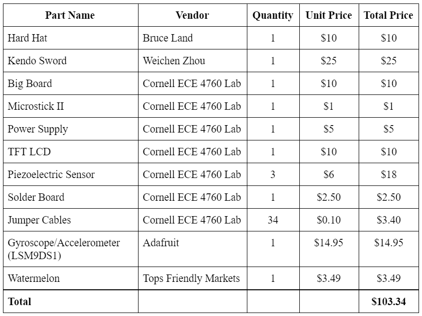
Appendix D: Project Cost Breakdown
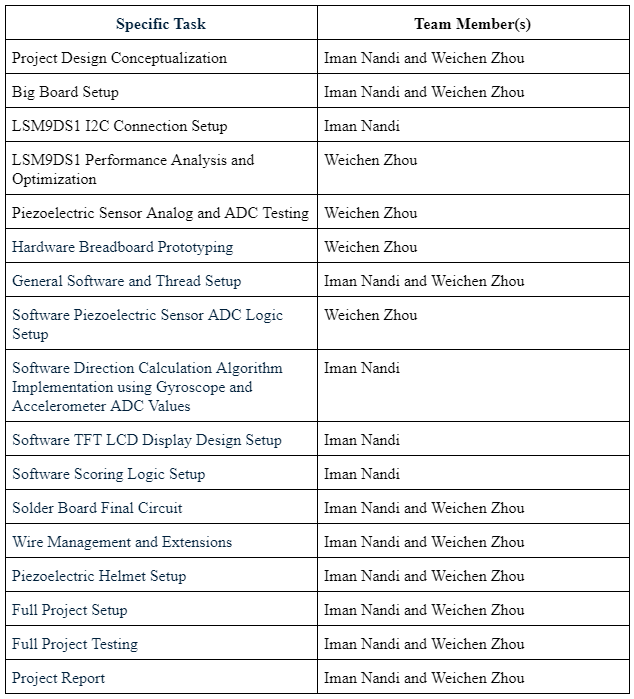
Appendix E: Work Breakdown
References
Microchip MCP6242 Op Amp Datasheet
PIC32 Family Reference Manual
LSM9DS1 PIC32 I2C Connection GitHub Source Code
Starlino Electronics Guide To using IMU in Embedded Applications