Distributed PIC Synthesizer
by Mark AnastosIntroduction
In this project, I have created a musical synthesizer with the ability to generate realistic instrumental sounds and to record songs for playback with harmonization.
Controlled by a PIC32 microcontroller, the synthesizer has over a full octave of buttons, laid out like a piano, to allow playing notes and making chords. It combines additive synthesis and enveloping to recreate the sounds of three different instrumental options. Furthermore, the system features two additional PIC32s which enable recording multiple songs and playing them back concurrently to produce harmonic musical compositions. The final product is described and demonstrated in the video below.
High-Level Design
A primary goal of this project was to create a system which a musician could use to perform reasonably complex songs and produce a pleasant sound output. In pursuit of this goal, I designed the user interface to contain the familiar piano keyboard layout of buttons to play the notes in the standard musical scale. To enable a wide variety of songs to be played, the keyboard has eighteen buttons for playing notes which span from C to F an octave higher. This allows chords with a wide range of notes to be played. Additionally the synthesizer features buttons to change the octave up and down, within a reasonable range, to allow an even wider range of notes, although not to be played in the same chord.
To allow for performing more complex songs than could reasonably be played at one time, the synthesizer has buttons to support recording and playback of songs. Once recorded, a song can be sent to either (or both) of the two helper PIC32 microcontrollers. With a song loaded, each helper PIC can be set independently to either playback the song once, or repeat it until stopped. The sound from each PIC is outputted through a digital-to-analogue converter (DAC), and then added together with the others via an analogue voltage adder circuit. Use of the recording feature is demonstrated in the video below.
In order to produce pleasant, realistic instrumental sounds, the synthesizer uses additive synthesis along with an enveloping function. There are three sounds available for use, selectable via buttons. The first sound is meant to replicate a piano; the second, an organ; and the third, a plucked string. Each sample for playing a single note is produced according to the following expression.

In this expression:
- t is the time since the button for the note was initially pressed down
- env is the amplitude envelope function
- ah is the amplitude for the hth wave in additive synthesis
- rh is the harmonic frequency ratio for the hth wave in additive synthesis
- ωn is the base frequency for this note
Of the above variables, env, ah, and rh are what differentiate the three sound types from each other. Each sound has its own unique envelope function as well as harmonic frequency and magnitude ratios. Not represented in this equation is the release of the note. When a note button is released, the sound does not abruptly stop, but instead is quickly faded away by the multiplication of a second envelope function, which is the same for all notes and sound types. The video below demonstrates the three different sound types with their unique envelopes and frequency profiles.
Below is a graph of the envelope functions used for the piano, organ, and plucked string sounds, plotted in relative units of amplitude over t in seconds, as well as a table of the additive synthesis parameters for each sound with amplitudes and frequencies relative to the base. These values were determined through experimentation as well as through FFT analysis of recordings of the respective instruments in MATLAB.
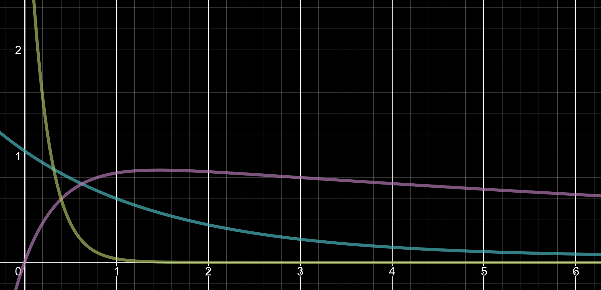
| Piano | Organ | Plucked String | |||
|---|---|---|---|---|---|
| Frequency | Amplitude | Frequency | Amplitude | Frequency | Amplitude |
| 1 | 1 | 1 | 1 | 1 | 1 |
| 2 | 3.433 | 1.5 | 0.6608 | 2 | 0.4563 |
| 3 | 1.836 | 3 | 0.7184 | 3 | 0.1282 |
| 4 | 0.7996 | 6 | 1.103 | 4 | 0.08147 |
There are not very many standards that apply to this project. However, one that is relevant is the conventional audio sample rate of 44.1kHz. In this project I did not use that sample rate, as it would put too tough of a constraint on the computation time for additive synthesis. Instead I used a sample rate of 40MHz / 2048 = 19.53kHz, which observationally seemed to give the best trade-off between computation time and audio quality. Also, the synthesizer has a standard 3.5mm audio jack to output audio to speakers or headphones.
Hardware Design
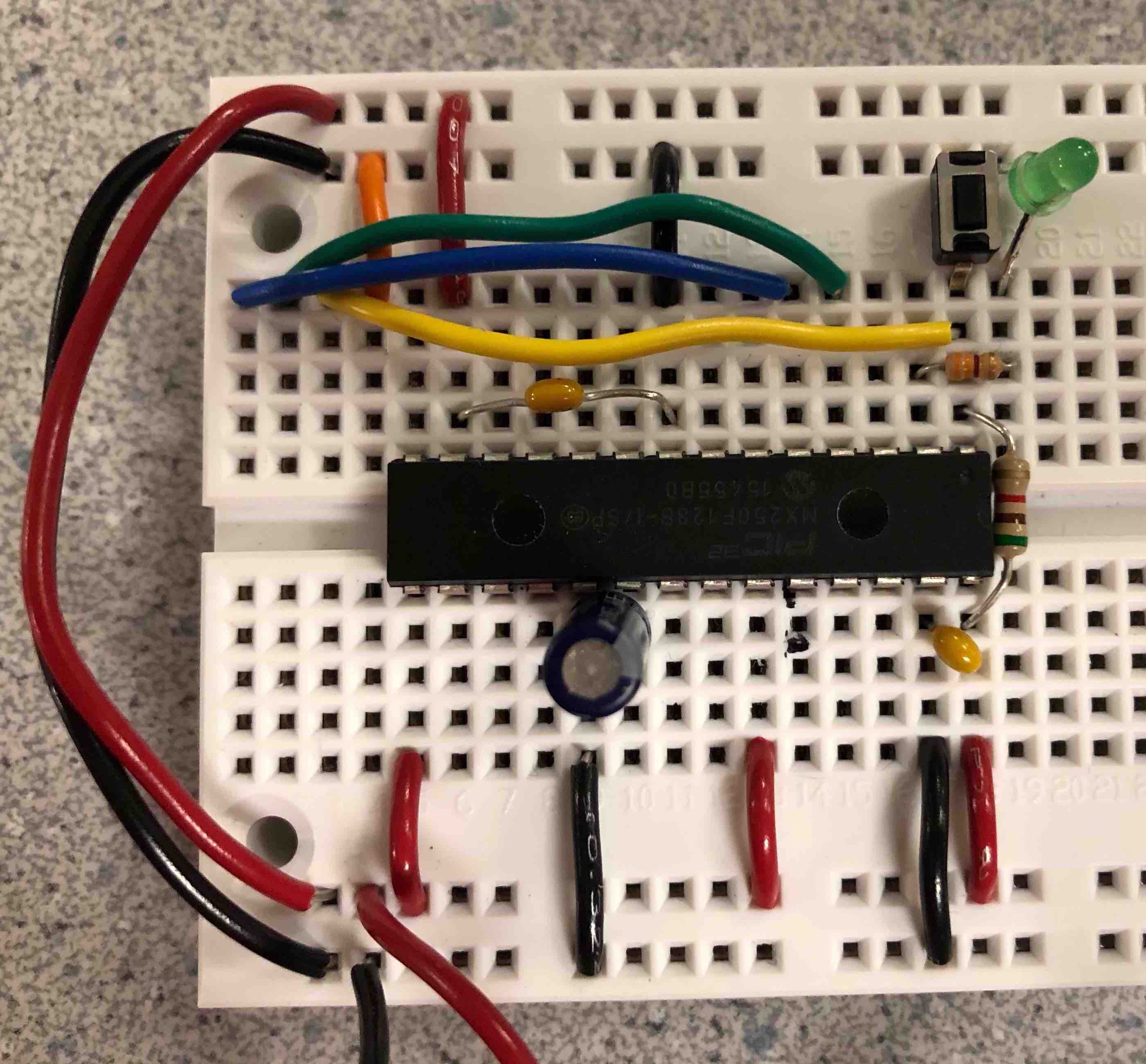
The first step in designing the hardware for this system was to create a method for powering and programming the PIC32 microcontroller without the use of any specialized printed circuit board. To do this I followed this guide, and created a minimal circuit for programming the PIC.
With this circuit in place, I was then able to extend it to create the full synthesizer. The next step was to hook up the DAC (MCP4822), as well as the port expander (MCP23S17) over SPI. Both were connected to SPI channel 1, with different chip select pins. The port expander was necessary in order to get all thirty button inputs. In order to connect thirty buttons to the PIC without using thirty pins, I created a matrix circuit. A matrix circuit combines input and output pins to be able to identify a large number of connections with a smaller number of ports. The software iterates through the output pins, setting one high at a time, and recording all of the input pins for each iteration. A simple matrix circuit is shown below.

In this example, the number of ports is equal to the number of buttons, and as such the matrix circuit is not really beneficial. However, showing much larger matrix circuits would be cumbersome. In the real circuit for the synthesizer, the thirty buttons are read using four output pins and eight input pins. Because the input pins in the matrix circuit need to be pulled down, and the port expander only has interal pull-up resistors, a 10kΩ resistor was added to ground from each of the input pins. By adding diodes (1N4001) to each button in the matrix circuit, we prevent possible false positives in reading the buttons.
In order to create the helper PICs, the same basic circuit design for programming the microcontroller was used, with another DAC added for each helper over their SPI channels. I was unable to get SPI communication working between the PICs, and as such I decidedd to use UART for this communication instead. Because the slave PICs never need to send data back to the master, the same UART channel could be used for both of them.
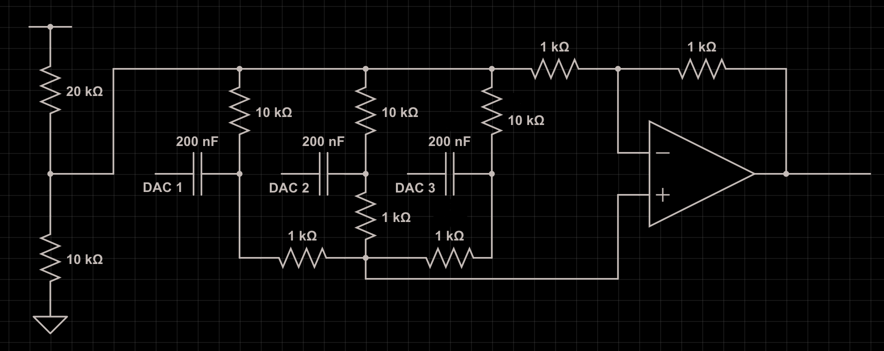
With the slave PICs in place, the last major hardware element to implement was the analogue voltage adder for the audio output. In order to add the AC components of the three voltages, I needed to DC bias all of the signals to the same voltage, somewhere between the minimum voltage on the board (0 V) and the maximum (3.3 V), so that the op amp (MCP6242) could amplify in both voltage directions.
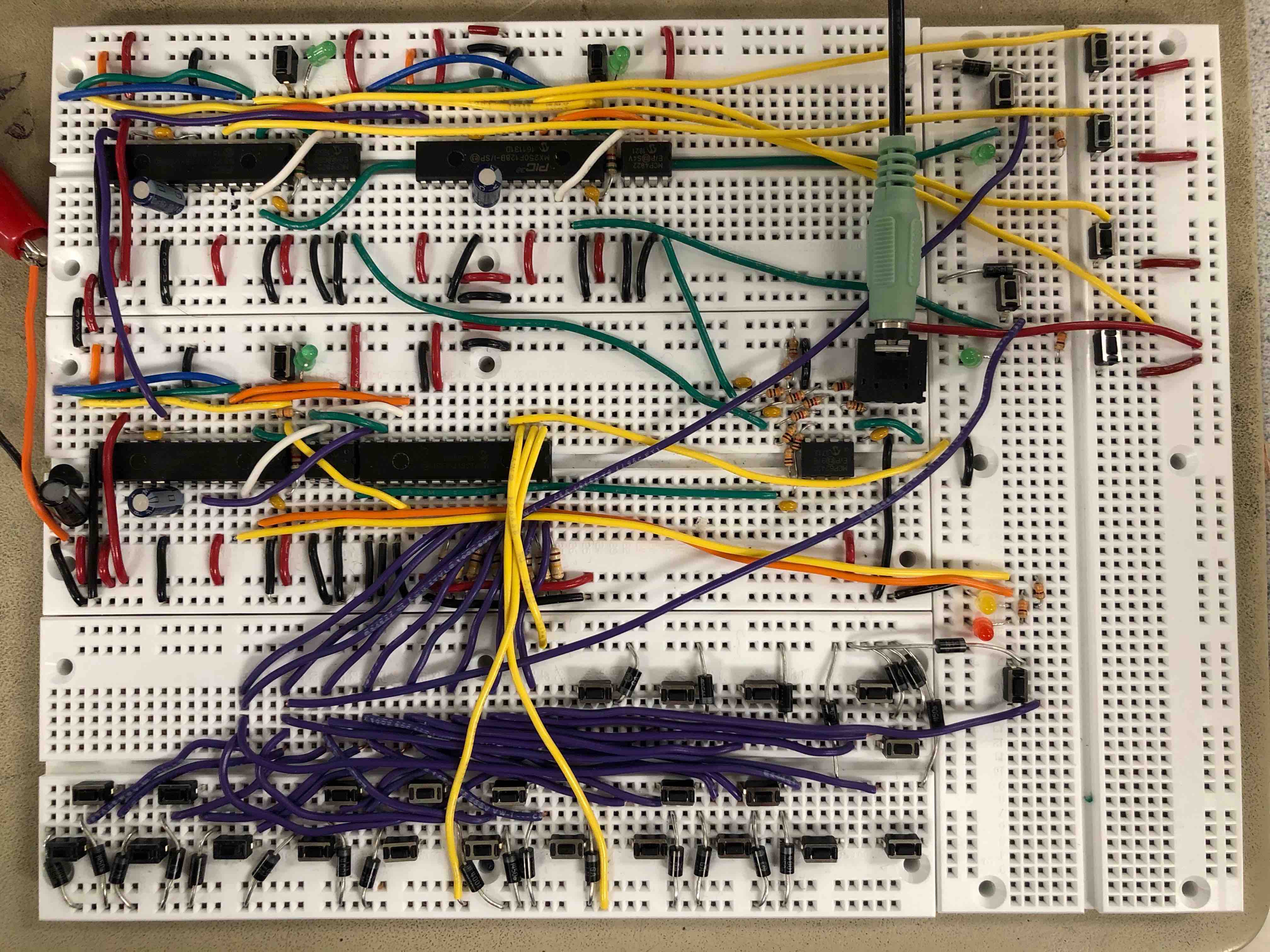
The completed synthesizer hardware:
Software Design
The software for this project can mostly be divided into three components: button detection, additive synthesis, and inter-PIC communication.
Button Detection
The software for dealing with the matrix circuit involves iterating through setting the output ports high and reading all of the input ports for each one. The algorithm for getting a single sample of all of the buttons is fairly simple.
for (i = 0; i < 4; i++) {
    DISABLE_ISR;
    writePE(GPIOZ, 1 << i);
    btn_samp.c[i] = readPE(GPIOY);
    ENABLE_ISR;
}
The code iterates through the four output ports, and reads the eight inputs into
an array of chars. We need to disable the interrupt service routine
(ISR) while doing this because both the ISR and the port expander use SPI, and
we do not want their sessions to overlap. Interestingly, disabling and enabling
the ISR on each iteration of the for loop instead of once for the entire thing
has a significant impact on the audio quality of the system. This is because if
the ISR is disabled for too long, the effect on the output signal becomes
noticable. In this code btn_samp is of a special union type
between a char[4] array and an int. This type is also
used for UART communication, but is helpful hear to combine all of the buttons
into a single variable.
In order to reduce double-presses, these buttons are debounced in the software. We give each button a state, which represents if it is canonically pressed or not. Then we only modify the state if the current sample from the matrix circuit and the previous sample agree with each other that the state has changed. Then, if we want to see if a button was just pressed or released, we see if the current state is different from the previous state. The debouncing functionality is all completed through bitwise operators, as all the buttons are stored in the same 32-bit variable.
For each button that controls playing a note, we have another state, the note state, for controlling when the sound should start and stop. For each note, we check to see if the button state has changed, and change the note state accordingly. We also record the press or release into an array if recording is on.
for (i = 0; i < NUM_NOTES; i++) {
    int btn = btn_st.i & (1 << i);
    int btn_prev = btn_st_prev.i & (1 << i);
    if (btn != btn_prev) { // debounced state transition
        if (btn) {
            notes[i].state = 1; // note starts playing
            notes[i].env_idx = 0;
            notes[i].rel_idx = 0;
        } else {
            notes[i].state = 2; // note released
        }
        if (recording) {
            recorded_notes[recorded_count] = i;
            recorded_times[recorded_count++] = recording_time;
        }
    }
}
The other buttons control other components of the sound synthesis, and the inter-PIC communication, and we handle these upon detecting a state transition from unpressed to pressed.
Additive Synthesis
In order to efficiently compute the additive synthesis algorithm as described in the High-Level Design section, we make heavy use of lookup tables so as to swing the space-time tradeoff more towards speed. We compute four sine tables, each containing 512 samples of the sine function over the course of one cycle. We use four of these tables instead of one because each note played has four harmonic frequencies in the additive synthesis equation. And each harmonic frequency has a different amplitude for its sine wave. As such, by having four sine tables, we can precompute the multiplications for those amplitudes, reducing the number of expensive multiplication operations required every each sample. Each time the sound type being used is changed, these sine tables need to be recomputed. But that is not a big deal, as this operation is infrequent, and does not need to be computed in the frame of microseconds, but instead of milliseconds.
We also have a lookup table for the envelope functions. These tables are the same size, 512 entries, as, although a cycle of the envelope function lasts about 6 seconds, the same envelope value can be repeated for many cycles without it causing noticably poor quality.
To represent the full, current state of each note, we keep an array of structs, where each struct contains the pressed state of the note, as well as the frequencies of all of its sine waves in the additive sythesis, as well as each wave's current index in its sine table. The notes also each need to keep track of their index in the envelope function table, as well as the release envelope table (for immediately after the button is released).
struct Note {
    volatile char state;
    _Accum inc[SINES_PER_NOTE], idx[SINES_PER_NOTE];
    int env_idx, rel_idx;
};
The central component of the additive synthesis algorithm is the ISR itself, which computes the output to the DAC for every sample. In this part of the code, we iterate through all of the notes. For each note that should currently be making sound, we iterate through each sine wave for that note and add the current value. Then the note's total gets multiplied by its current value of the envelope function(s).
_Accum out = 0;
int i, j;
for (i = 0; i < NUM_NOTES; i++) {
    struct Note * note = ¬es[i];
    if (note->state) { // pressed or recently released
        _Accum out_i = 0;
        for (j = 0; j < SINES_PER_NOTE; j++) { // add each freq component
            _Accum idx = note->idx[j];
            out_i += sine_tables[j][(unsigned int) idx % SINE_TABLE_SIZE];
            note->idx[j] = idx + note->inc[j];
        }
        if (note->state == 2) { // released
            out_i *= rel_table[min(note->rel_idx++ >> 8, REL_TABLE_SIZE - 1)];
            if (note->rel_idx >> 8 == REL_TABLE_SIZE)
                note->state = 0;
        }
        // multiply by envelope function and add to total output
        out += out_i * env_table[sound][min(note->env_idx++ >> 8, ENV_TABLE_SIZE - 1)];
    }
}

recording_time++;
Inter-PIC Communication
In order to send a full song to another PIC over UART, we need to have a scheme
to unambiguously describe a song. The first thing that needs to be sent in order
for the full system to work properly is an identifier to differentiate which
helper PIC is being addressed. Because all three PICS share the same UART line,
there needs to be a mechanism to make this distinction. As such, we send a byte
with value 0 or 1 first to address a single PIC. The
next thing that needs to be sent is the number of commands that were recorded,
so that the slave PIC will know when the transmission of the song has completed.
After that we send the initial state of the recording, including what octave the
synthesizer was initial in, as well as the initial sound type. After that we
send the lenght in time of the song (in units of audio samples) so that the
slave PIC will know when it has reached the end of the song. After that we send
the sequence of commands recorded, including a command identifier byte for each,
as well as the time at which it was issued.
void sendRecording(char slave) {
    mPORTASetBits(BIT_0);
    SEND_BYTE(slave);
    int i;
    for (i = 100000; i--;);
    SEND_BYTE(recorded_count);
    SEND_BYTE(initial_octave);
    SEND_BYTE(initial_sound);
    SEND_INT(recorded_length);
    for (i = 0; i < recorded_count; i++) {
        SEND_BYTE(recorded_notes[i]);
        SEND_INT(recorded_times[i]);
    }
    mPORTAClearBits(BIT_0);
    mPORTBClearBits(BIT_13);
}
Notice how we delay between sending the first bit and the rest. This is to let
the slave PIC have time to notice the transmission has started without missing
any of the data, which would cause the slave to fail. SEND_BYTE and
SEND_INT are macros which send data over UART.
SEND_INT does four transmissions using a union data type, as only
one byte can be sent at a time over UART.
Results & Conclusion
The performance of the synthesizer was better than I originally anticipated it
to be. Any individual PIC is able to play up to eight notes at a time with no
issues or decrease in audio quality. This is the result of a few things. One is
that the large number of lookup tables meant that only one multiply is needed
per note being played per cycle (multiplying the envelope function by the sumed
sine waves). Actually, technically two multiplies are needed for a note when it
is in the released state, but this state only runs for a short period of time.
(If you try to play nine notes at the same time, the PIC only slows down if you
release them all at the same time giving 18 total multiplies in a cycle.)
Another reason for this efficiency is that I found out how to enable the
-O1 compiler optimizations in MPLAB X, which had a considerable
effect on the program speed.
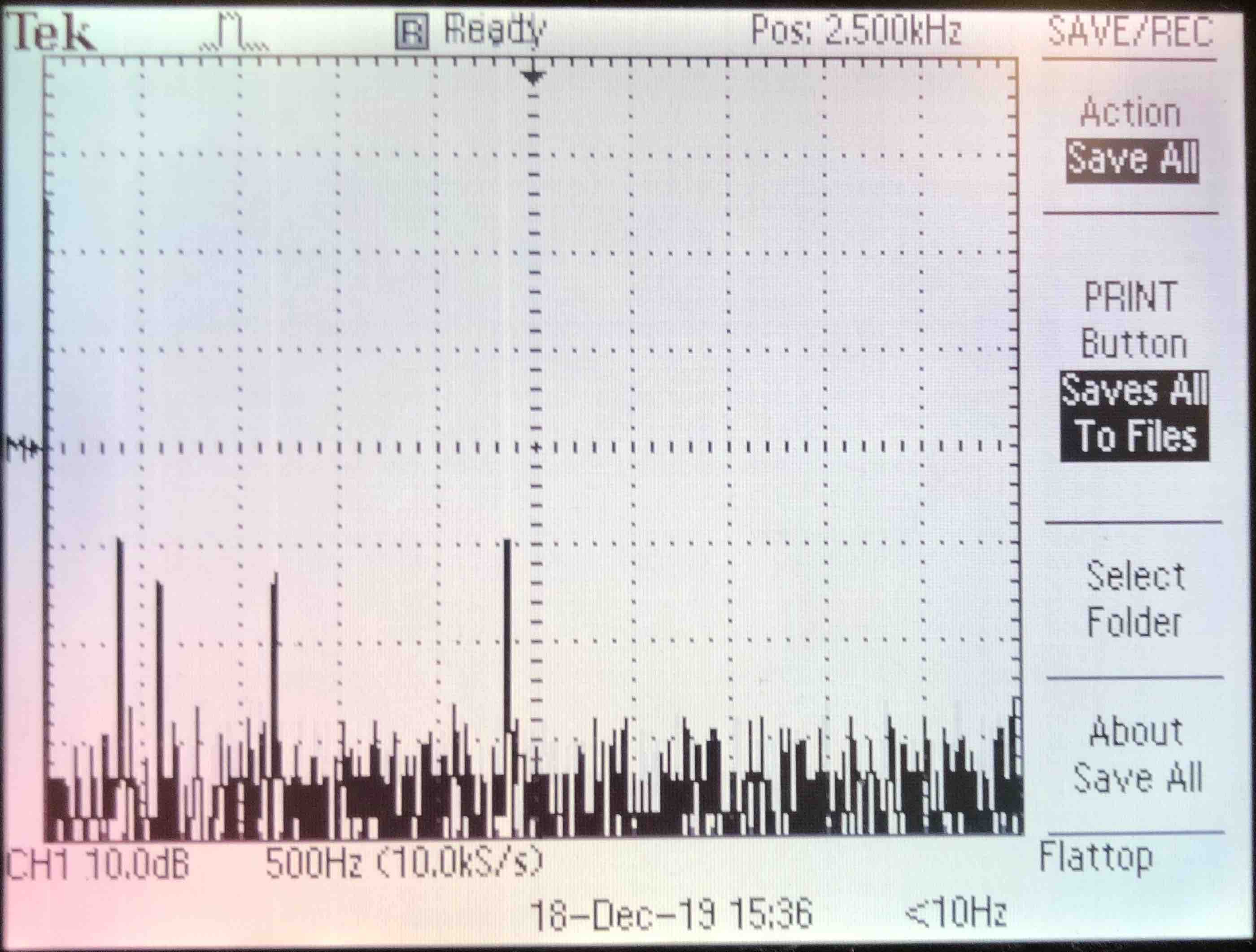
The quality of the audio output also turned out quite well. There is very little noise in the sound, and the additive synthesis creates fairly realistic sounds. I especially enjoy the organ sound, which to me sounds surprisingly close to a real organ. I did not think this would be achievable, as real organs have a very wide and scattered frequency spectrum. Below is a FFT of the note G played with the organ setting, which has very little noise. I chose to show the FFT of the organ sound, as this is the only one whose envelope does not decay too much, and as such it was easy to get a good image of the frequency spectrum.
In general I am fairly happy with the results of this project. However, there is one area in which I think it lacks if attempting to be a truely usable synthesizer. That area is the timing of recordings. As it currently stands, the sythesizer offers no good way to synchronize the playing of multiple recordings. The recording starts immediately when you press the button, and ends immediately on the next press. And the same is true for the playback. I think it would be a significant improvement to the project to have some mechanism to better time the songs. I do not know exactly what that would be (which is the main reason its not in the project), but it is definitely an area open for improvement.
Appendices
A: Permissions
- The group approves this report for inclusion on the course website.
- The group approves the video for inclusion on the course youtube channel.
B: Source Code
The full listing of the source code for this project is
available on GitHub.
The main code for the master PIC is in synth_master.c, and for the
slave PICs, in synth_slave.c.
C: Cost Details
All of the components used in the creation of this synthesizer were acquired from the lab for this course.
| Component | Quantity | Price ($) | Total ($) |
|---|---|---|---|
| Microstick II | 1 | 1 | 1 |
| Breadboard | 4 | 6 | 24 |
| Power Supply | 1 | 5 | 5 |
| PIC32 | 3 | 5 | 15 |
| I/O Expander | 1 | 5 | 5 |
| Lab Speakers | 1 | 2 | 2 |
| Total | 52 |