WoodPlay
A Wooden Piano Arcade
A Project By Xiangyi Zhao & Alga Peng.
Introduction
WoodPlay is an electrical music device with two modes - Self-play and Arcane. In the Self-play mode, players can play the 12 notes in a chromatic scale with the 4 wooden keys and 3 keypad buttons for changing the group of displayed notes. Due to the budget and hardware constraint, we have 4 potentiometers, each corresponding to one note. The Arcade mode contains three levels of difficulties and requires players to press buttons in a sequence dictated on the screen.
High-Level Design
Rationale and Sources
We choose this project idea because Alga has been interested in the music-related fields in ECE and we’re both profound rhythm game and arcade players (and watchers). This interest has inspired us to build a piano-shaped instrument and rhythm game in the context of the ECE 4760 final project.
In the beginning, we have been considering building a 7-key piano, each associated with pitch do, re, mi, fa, so, la, si. However, since the key-presses are detected by low-torque potentiometers, our budget can’t afford 7 of them. In the end, also taking the space of our piano into account, we settled with 4 keys and a keypad to switch pitch.
User Interface
As WoodPlay is turned on, a menu presents the choice of two modes - Self-play and Arcane - and the corresponding keypad buttons to press.
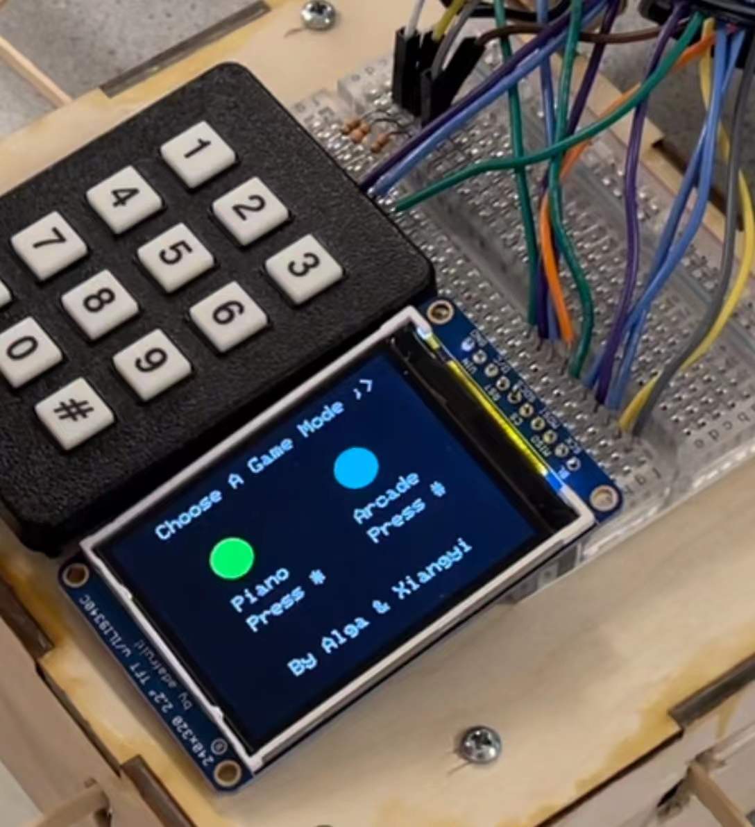
Figure 1. Main menu
After choosing the Self-play mode, a drawing of the 12 piano keys in a chromatic scale is displayed on the screen. By default, the 4 wooden keys are not mapped to any pitches. Players should press 1, 2, or 3 on the keypad in order to map the 4 keys to different groups of notes. The piTFT will display what note each key is mapped to under the current keypad pressing. To be more clear to the players, we named each wooden key A, B, C, and D, and wrote these letters explicitly on the physical layout. We also indicated on the bottom that players can press 0 on the keypad to return to the main menu.
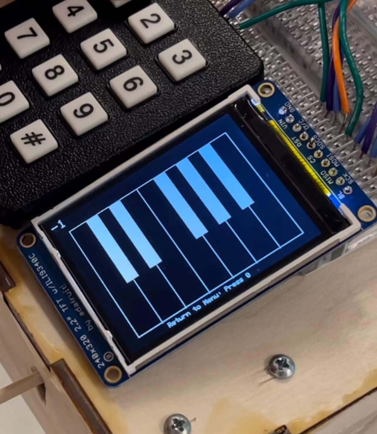
Figure 2. Self-play mode, no group is selected
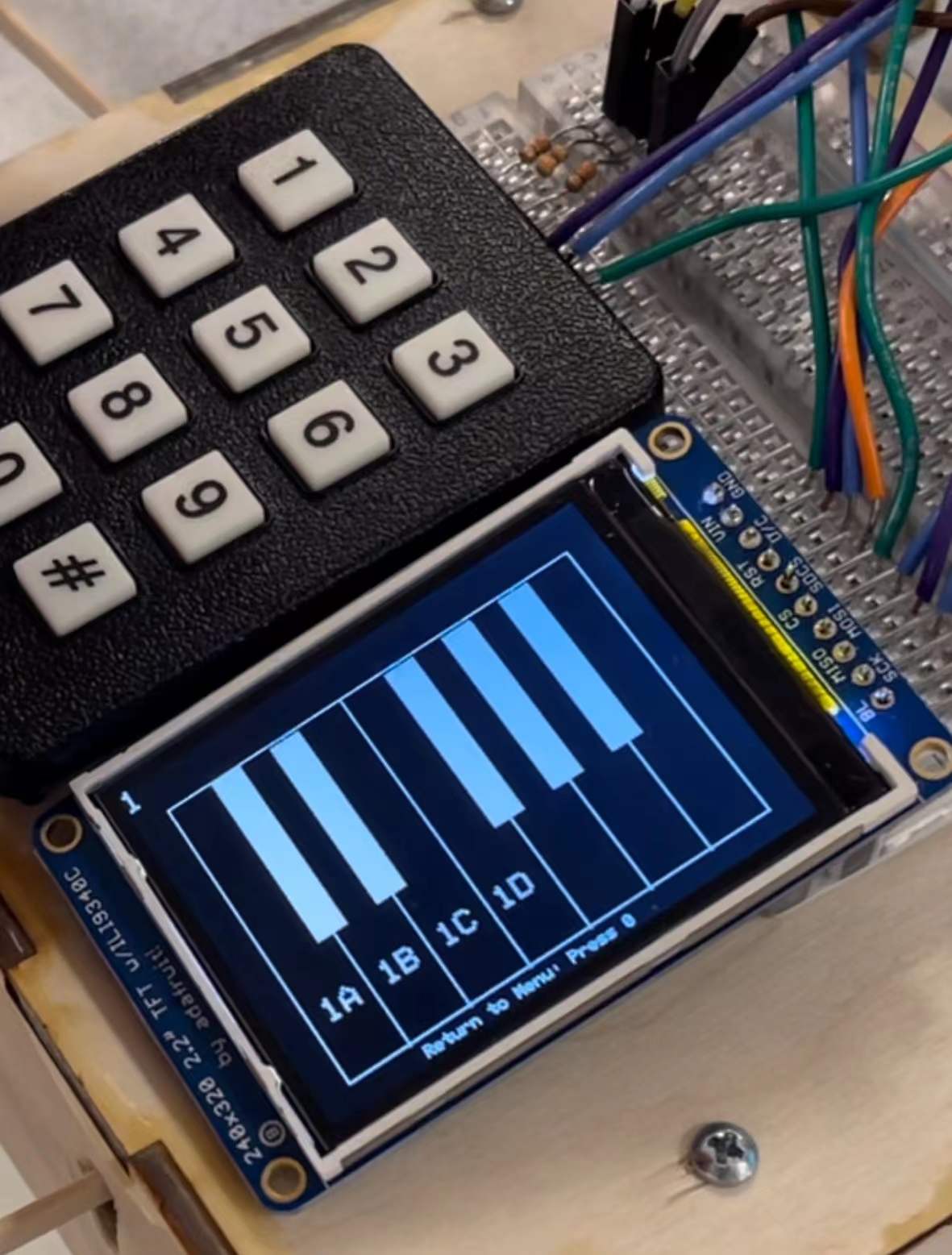
Figure 3. Self-play mode, the first group of notes is selected
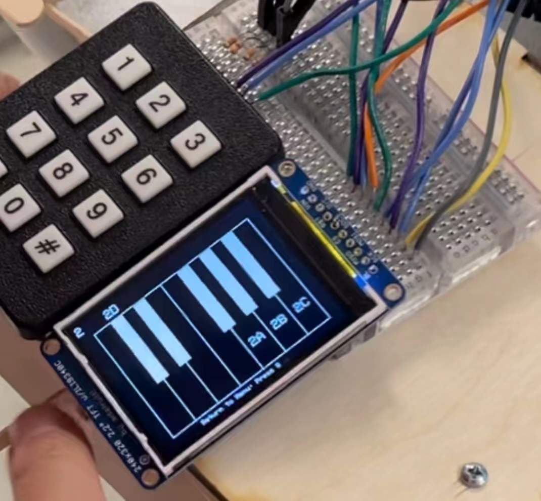
Figure 4. Self-play mode, the second group of notes is selected
Due to the limited time we have on our project, we only covered one chromatic scale. Later we can cover more scales by using more keypad keys for switching. Given that the PiTFT may be too small for displaying more scales, we may consider using a larger screen or moving the whole display onto a Python interface on the computer.
If the players choose the Arcane mode, a second-level menu will appear for them to choose the difficulty levels.
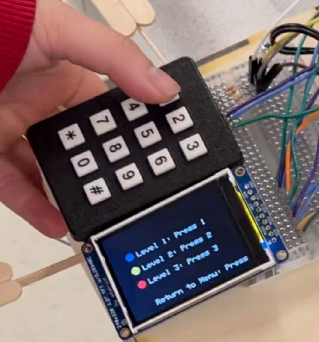
Figure 5. Difficulty level choosing menu for Arcade mode
Each level has a different sequence of notes falling down from the top of the screen on 4 tracks, each mapping to a wooden key. The players should hit the corresponding wooden key when the note passes the bottom line. A higher level indicates a longer and more intense sequence which requires higher skills of the players (which neither of us have right now). If the wooden key is pressed within a reasonable range of time before the note falls on the line, a “PERFECT” will show up next to it. If the hitting is off by a certain point or there is no attempt at all, a “MISS” is shown.
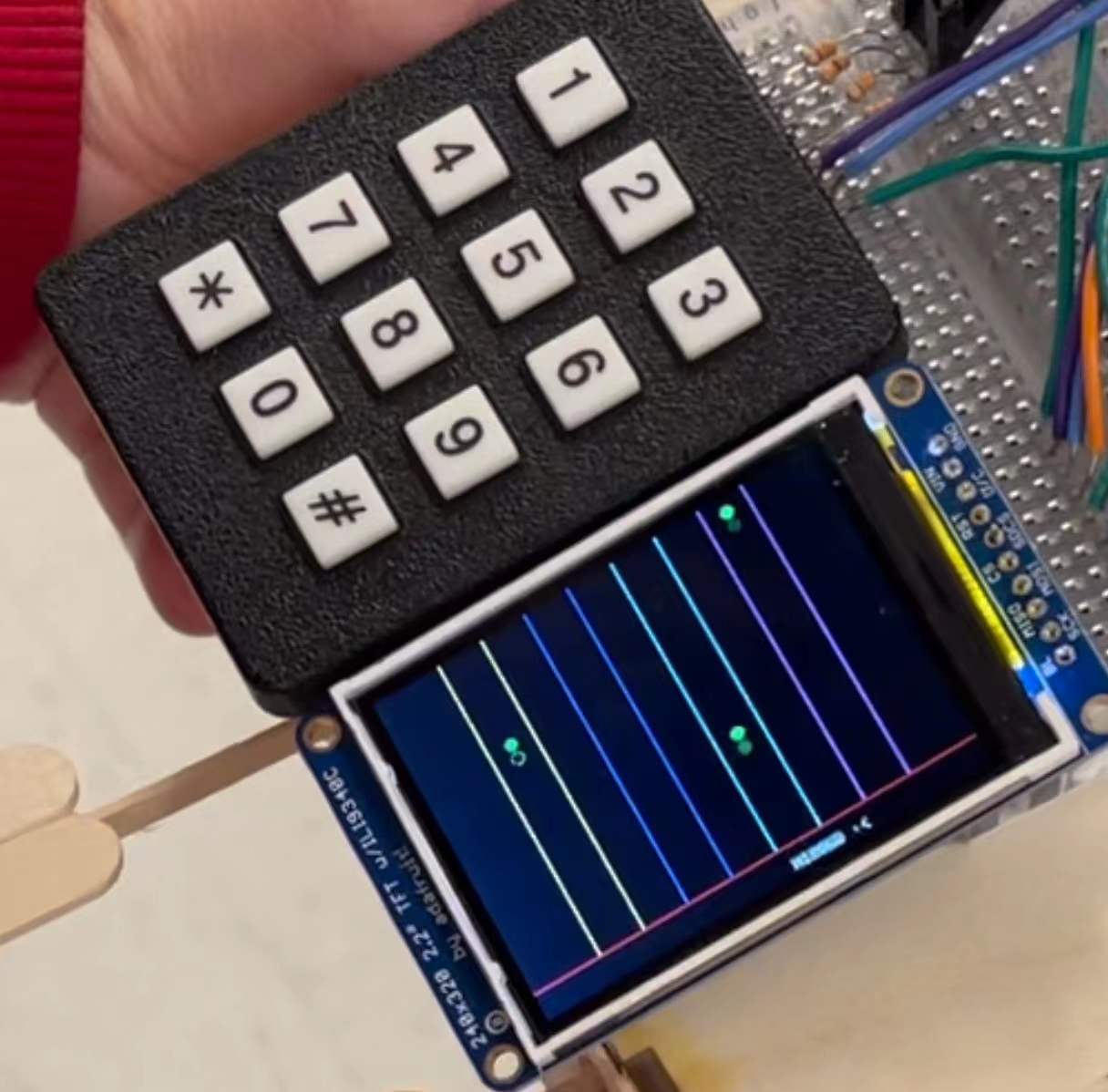
Figure 6. The note sequence on 4 tracks in Arcade mode
After the level is finished, there is a summary of the number of notes a player hit perfectly or missed. We also indicated on the bottom that players can press 0 on the keypad to return to the main menu. We may advance this setting by having both “returning to the main menu” and “selecting another level” to save the players from unnecessary moves.
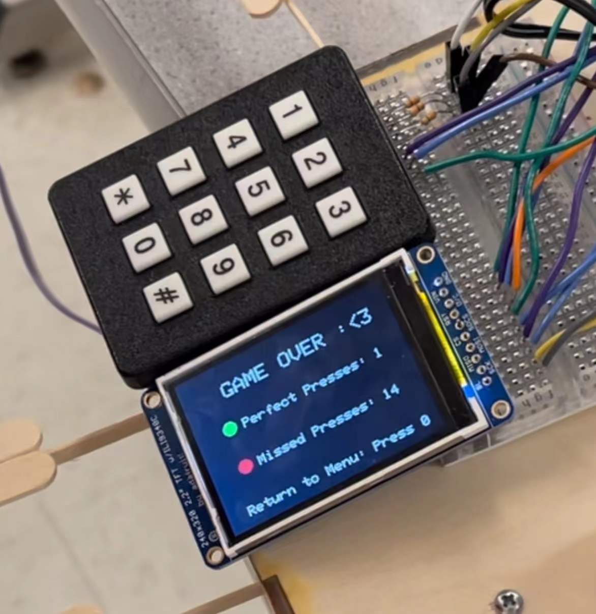
Figure 7. The summary at the end of one level (yeah we haven't gotten good at it yet!)
Background Math
The way of generating our desired sound is to use Direct Digital Synthesis, which uses a 32-bit accumulator to scale the range of phasor angles from 0→2π radians to 0→232−1. The increment of the accumulator and its phase is calculated according to the sample rate and desired output frequency for each key, each time in the ISR, it selects the phase value according to the wooden key pressed and the keypad number, shifts the phase right by 24 bits to use the most significant 8 bits to index into the sin table, envelopes the derived signal, and outputs the signal into the DAC_A channel.
Logical Structure
Main threads used in our program are:
User input and response threads: Press_wooden_key, Press_keypad
Drawing threads: Menu, Self-play_draw_notes, Self-play_cleanup, Arcade_draw_notes
ISR, Timer thread
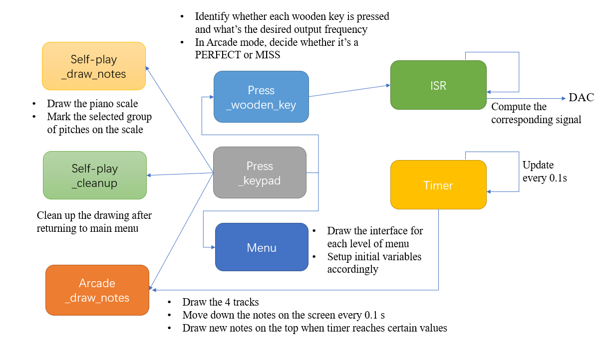
Figure 8. Flow chart of logical structure
The above flow chart captures the whole logical structure of our program. The Press_wooden_key and Press_keypad threads are responsible for taking in user inputs. The Press_wooden_key thread either computes the desired output frequency based on the signal it receives and the value of the keypad when in Self-play mode, or decides whether it’s a PERFECT or a MISS when in Arcade mode. The Press_keypad thread is the major control thread in our program, which is responsible for updating which state is the program in. There are four drawing threads - Menu, Self-play_draw_notes, Self-play_cleanup, and Arcade_draw_notes. These threads perform the drawing depending on the keypad presses.
Hardware Design
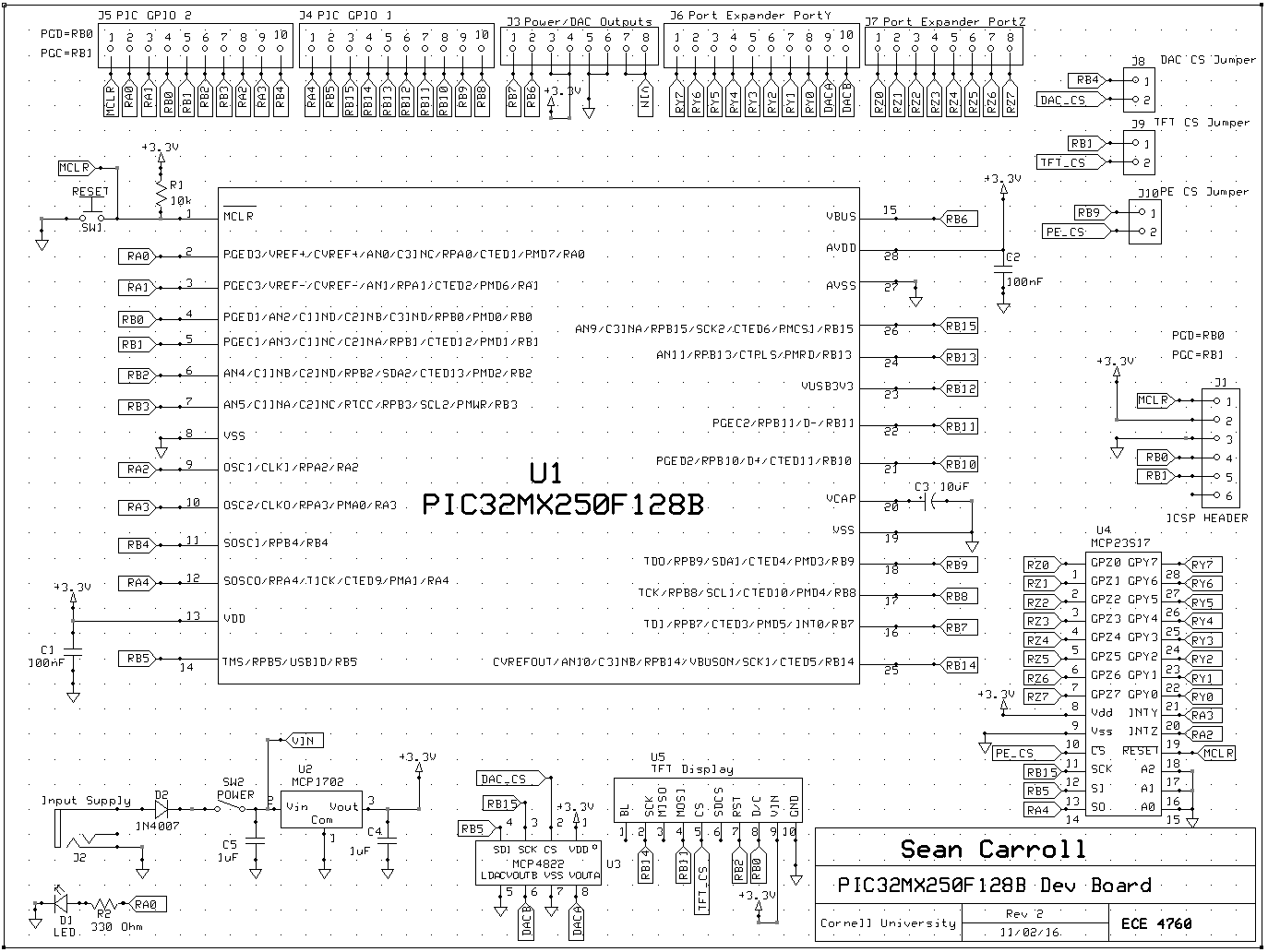
For this project, we combined designs from previous labs to construct an arcade for music games. We used PIC32MX250F128B(PIC32) with various peripherals including a keypad to take in user inputs, a TFT to display the user interface, a 12-Bit Dual Output DAC with SPI -- MCP4822 -- with an audio socket for audio outputs, 4 potentiometers for motor detection, Analog/Digital Converter, and MCP6242 opamp to build a low-pass filter for our design.
Pin Selection
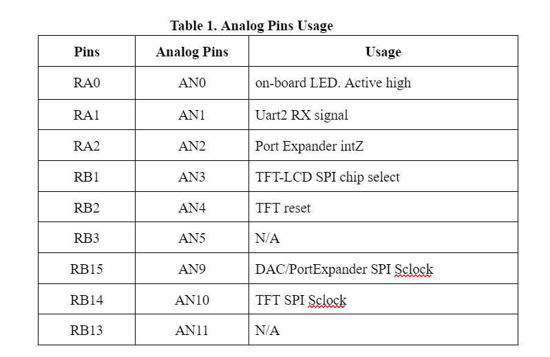
One challenge we encountered was how to connect all the peripherals to PIC32. Specifically, we need to select 4 pins for ADC inputs from potentiometers. To do so, we need to first know which pins are supported for ADC and determine if those pins are used for other peripherals already. From the I/O port layout we recognized that For the external keypad, we need to use the port expander to support the flexible connection of seven I/O pins to the PIC32. The keypad is connected to port pins Y0 to Y6: Y0 to Y3 are driven as outputs, while Y4, Y5, and Y6 are input with pullups turned on. Using a port expander means pins RA2, RA3, and RA4 are occupied. To support the TFT, which is used for game display, we need to use pins RB0, RB1, RB2, RB11, and RB14. For DAC SPI, pins RB4, RB5, and RB15 are occupied. We combined all the information known to determine what are the available pins left for ADC inputs. With that information known, we then compare it with the analog pins to see which ones are left.
The PIC32 10-bit Analog-to-Digital Converter (ADC) has up to 16 analog input pins (AN0-AN15), but we only have 9 on our package (AN0-5, AN9-11). Following Table 1 below, we see that only 2 pins are available: RB3(AN5) and RB13(AN11). Since we need a total of 4 pins, we need to modify the original settings to accommodate our changes. We first disconnected the LED from the board since it has no practical usage in our project and we could use RA0(AN0) which was previously used for the on-board LED. Then we commented out the UART setup portion in protothreads 1_2_2 to ensure that RA1(AN1) is safe to use now. So we determined that the four ADC pins to be used are: RA0(AN0), RA1(AN1), RB3(AN5), and RB13(AN11).
Physical Setup
To build the arcade, we chose a wooden box, two types of ice cream sticks to build the piano keys, and a cardboard box to protect the fragile hardware parts. Figure 9 and 10 below show our ultimate design. As shown in Figure 8, we separated the TFT with the board and used a half-sized breadboard to place both the keypad and the TFT screen on top of the wooden box. The audio socket is left outside on the top left corner of the wooden box for easy connection when playing the game. The cardboard box hides the board with PIC32 and another breadboard which is used for low-pass filtering all the inputs coming from the potentiometer.
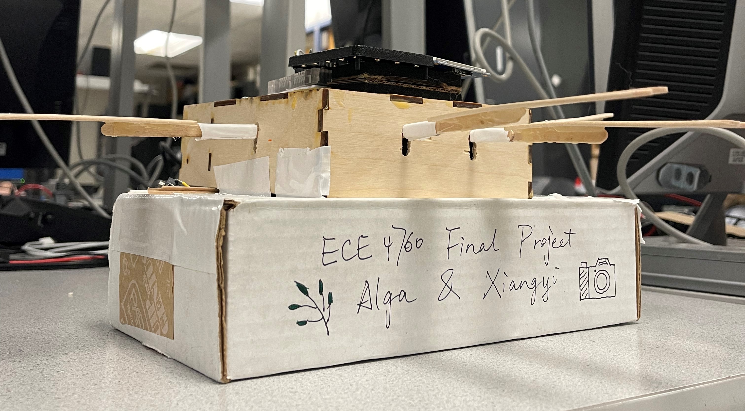
Figure 9. The front side of WoodPlay
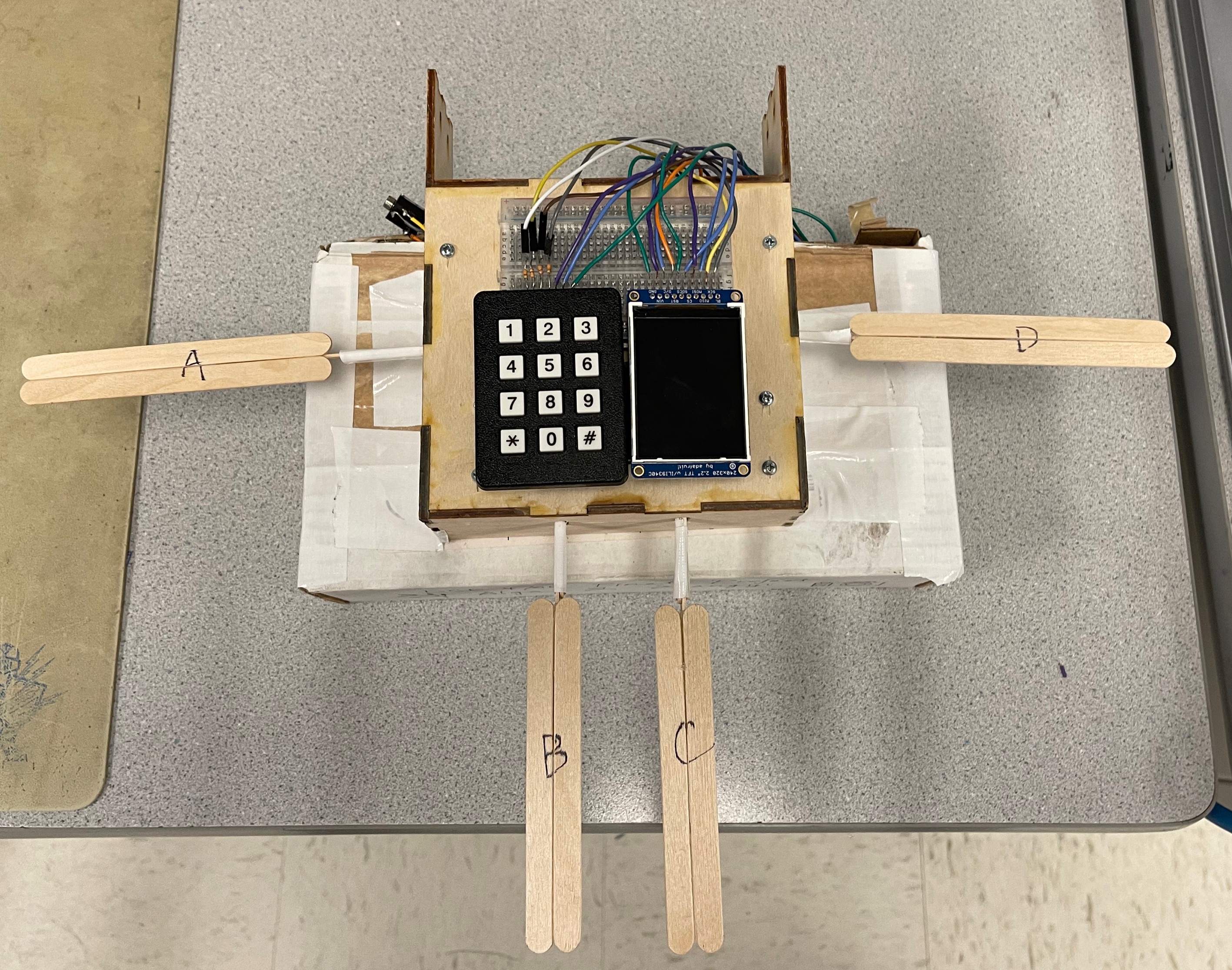
Figure 10. The top side of WoodPlay
Inside the wooden box, we placed 4 potentiometers and glued them with the sticks so that when the sticks are pressed down, the angles can be detected and ADC reading will indicate a press down. For the game to be playable, we need to ensure that the key bounce back to the horizontal position once released. Our original design is to use springs for bounce back, but the touch feels weird so we decided to use sponges instead. As shown in Figure 11 below, we drilled 4 holes for sticks and at the end of each stick a sponge was placed between it and the ceiling of the wooden box to support the bounce back effect.
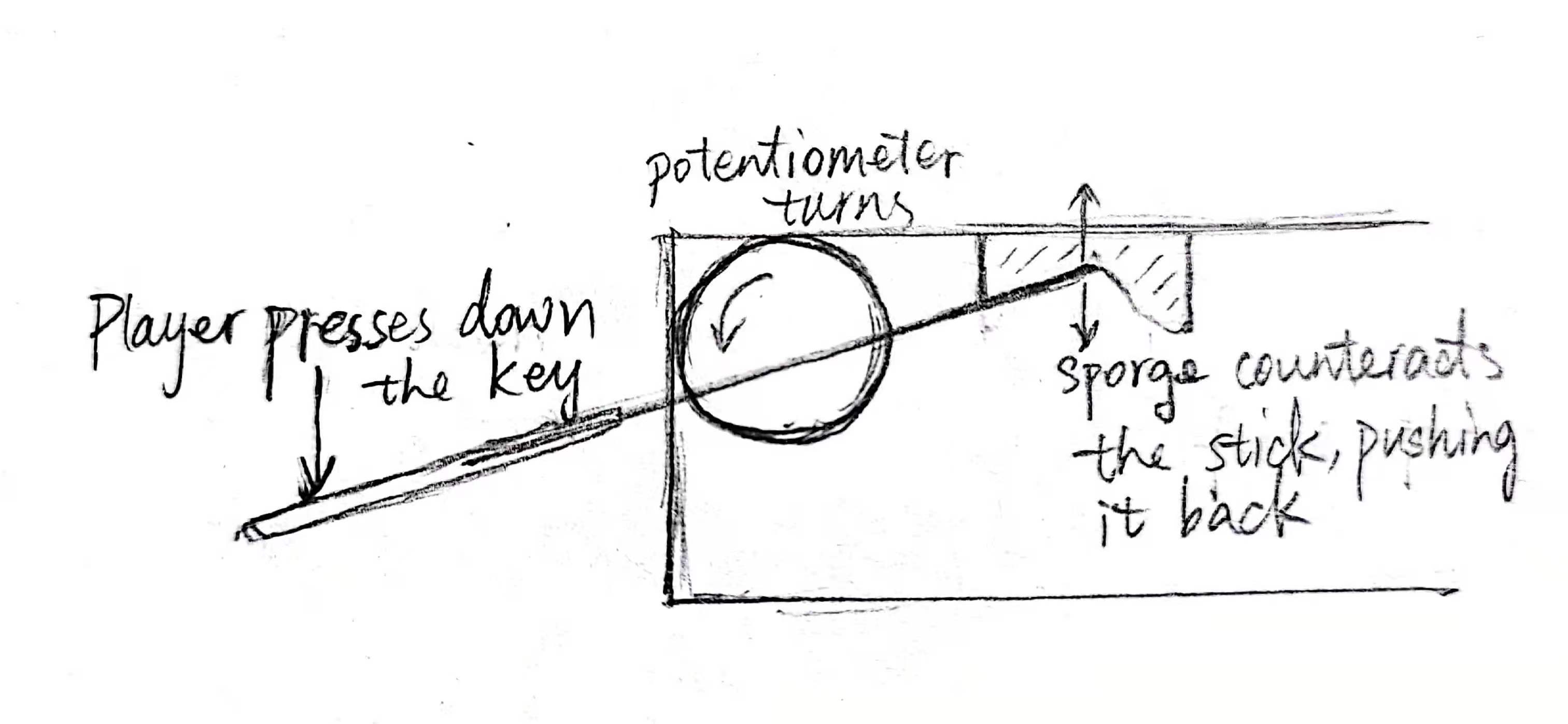
Figure 11. Sectional view of WoodPlay
Software Design
Keypad Configuration
We used keypad numbers to indicate which group of notes we are playing as described above. As in Lab 1, each key is labelled with a binary representation for us to pattern match with the inputs. We set up the keypad table as the following:
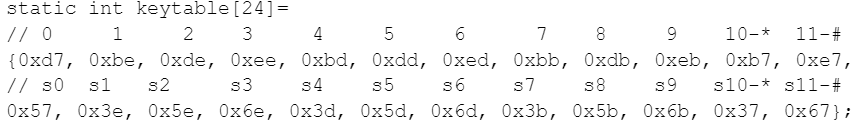
The binary representation of the number for each button matches the output and input pin values. For example, in the following Figure 12 below, it is shown that if key 0 is pressed, BIT_3 and BIT_5 should present 0. For number 0’s encoding: 0xd7 which is 11010111 in binary, matches the hardware result -- the last output bit is 0 and the second input bit is 0.
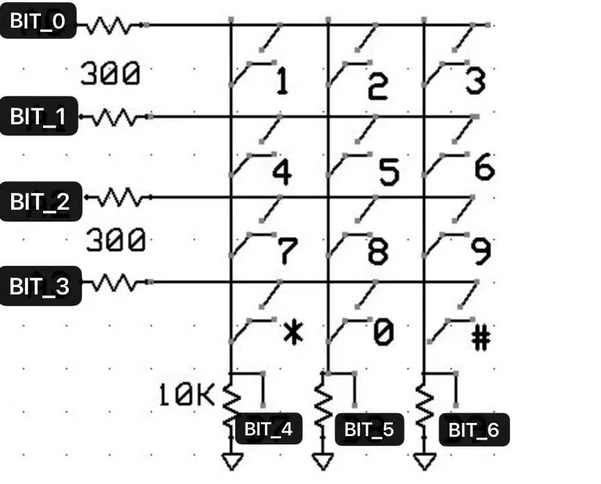
Figure 12. Keypad Software layout
We also introduced a global variable named key to store the last pressed key number. This is necessary because after the thread is scheduled, it constantly reads the input value and updates the current key reading, which is -1 if no key is pressed down at the moment. We need to store the information since we do not want to be constantly pressing the key. We also set everything back to its default state if key 0 is pressed.
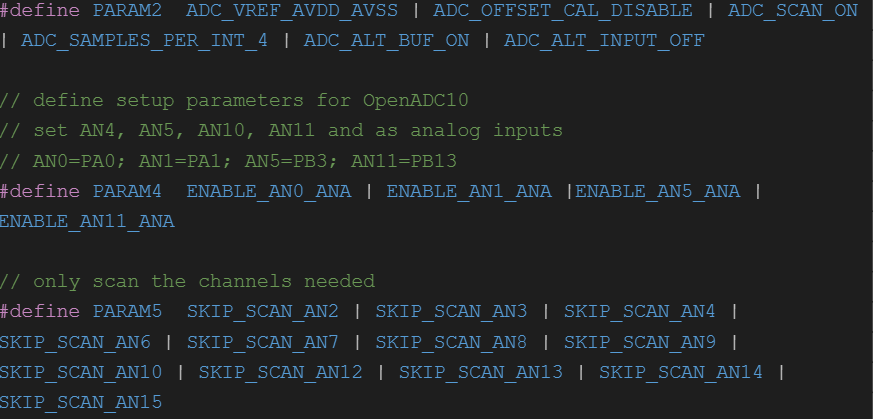
ADC Setup
For ADC setup, we modified the parameters to enable multiple readings of ADC inputs at the same time. First we need to enable scan mode, and indicate that we want to read in 4 samples per iteration, and specify that we need to use the alternative buffer. Then we defined the analog inputs and skipped scanning the other channels not needed following the code below. We also need to ensure that we use ground as a negative reference for channel A.
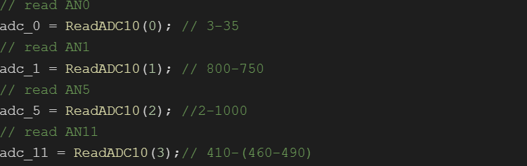
Once we successfully set up the ADC channel, we read the ADC inputs using the ReadADC10() function which takes in the ADC buffer number which is to be read. The 4 scanned values are stored into a hardware-defined array in order -- AN0 first, AN1 second, and so on. By reading the first 4 buffer we can get the results of the 4 inputs from potentiometers. With that information we printed out and recorded the value of idle states and pressed down states for each key. For example, we see Key A’s (which middle C in piano) ADC reading changed from 3 to 35 when pressed down. We simply use if statements to determine which is pressed and depending on which keypad key is pressed, output different sounds.
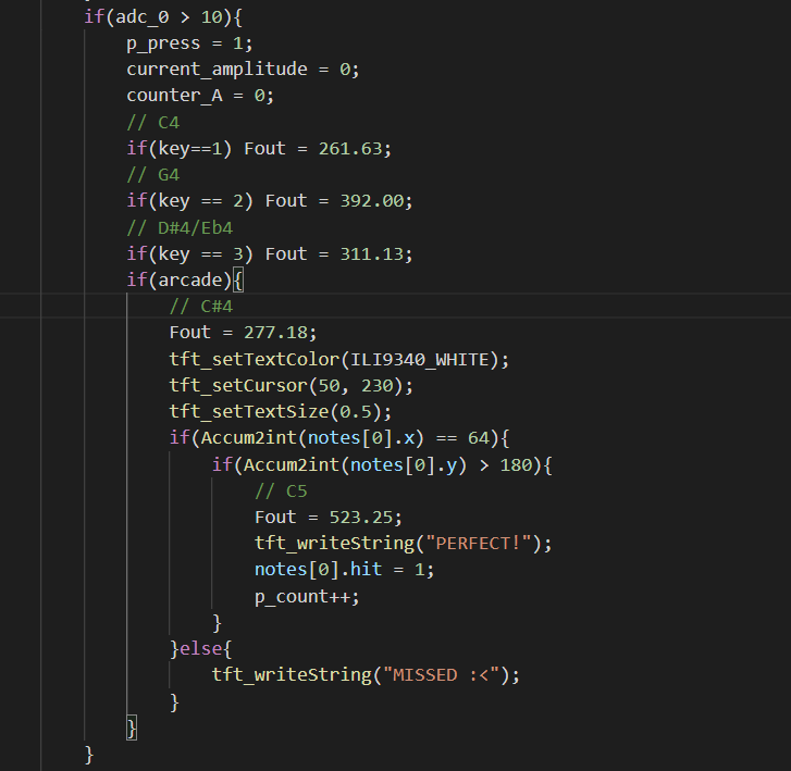
Below we show that when Key A is pressed, we set different frequencies to Fout, which is used for DDS calculation to output the corresponding sound. We also check if it is playing under Arcade mode, which does not have 3 distinguishable sounds and will only output C♯4 or a note that is a pitch higher than its original one if key 1 is pressed (C5 in this case). Since each key is responsible for a track, we can know the x and y coordinates of the hit points. When a key is pressed, we check the most recent node in the array, meaning that it is the closest one to the line, and check the x coordinate to see if it is within the track the key is responsible for. If yes then we check its y coordinate to see if the note is close enough to the line to determine whether it is a hit or a miss.
Self-play Mode
For self-play mode we originally wanted to import images of piano using bitmaps. After hours of experiment, we realized that we did not have enough storage for images and decided to use lines and boxes to draw the piano ourselves. As described above we used 3 keys to determine which group of notes the 4 piano keys are corresponding to. For future improvements, we want to extend that to contain higher and lower pitches. Since we still have buttons 4, 5, 6, 7, 8, and 9 on the keypad to use, we can contain two more pitches.
Arcade Mode
For each level of difficulty in the Arcade mode, there are two arrays storing the x-coordinate of each note and the time in 100 milliseconds that this note appears on the top of the screen. The x-coordinate value can only take 4 values - 64, 128, 192, and 256, thus the notes can fall down in four equally-divided tracks.

After entering the Arcade mode and choosing the level, the Menu thread will mark a variable level to be 3, 4, or 5, corresponding to the 1st, 2nd, and 3rd difficulty level in the game, and set the global time sys_time_100msec to 0. The Timer thread increments sys_time_100msec by 1 every 100 milliseconds (0.1 seconds), which keeps track of how much time has passed since the start of this level. The Arcade_draw_notes contains a while loop that maintains a frame rate of 30 fps. The thread reads the value of sys_time_100msec, and determines whether it has reached the time when a new node should appear on the screen from the top.
For the notes that are already on the screen, we wanted to move them down by a certain speed. We set this speed to be 10. However, given how badly we played it in the demo, we might consider lowering the speed further in the future :D All the notes on the screen are kept in an array notes with size 10 and there is a size counter that keeps track of how many notes are currently inside notes. In each iteration, we move all the notes in notes down by drawing a black circle at their original positions and re-drawing a green one at the new position. When a note moves past the bottom line, we delete it from notes by subtracting one from the size counter, which will prevent the program from updating its position on the next iteration. In this process, we also determine 1. whether there are no pressing attempts on this note at all, if so, a MISS will show; 2. whether this is the last note of the sequence, if so, we mark it to be the end.
Result
Demonstration Video
We implemented most of our desired features in this project except for the music feature in the Arcade mode. We originally wanted to play the music and based on the rhythm let the notes fall down. It was unfortunate that we did not have enough time to finish that implementation and we will be working on it in the future to incorporate the design into our project.
Conclusion
As mentioned above, we were inspired by Lab1 and Lab3 of this class and combined the two approaches to build our final project. Except for the reference code we were given in class, we did not refer to any other sources. We found the information we needed by reading the hardware manual, and asking Professor Hunter and course staff.
For safety concerns we strengthened our sticks with tapes so that it would not break easily even when players are pressing the keys too hard. Our project is legal and safe. We also believe that our project is consistent with IEEE code of Ethics because it does not indicate any kind of unfairness. It does not facilitate arguments among players since this is not a multiplayer game although it could be if wanted.
We want to thank all the course staff, Professor Hunter Adams, and Professor Bruce Land for their support and encouragement throughout the course. We enjoyed the class and had learned a lot from working in the labs.
Work Distribution

Project group picture
Alga
cp444@cornell.edu
Alga was responsible for hardware implementation such as pin selection, DAC SPI setup, ADC setup, keyboard setup, constructing part of the user interface, etc.
Xiangyi
xz598@cornell.edu
Xiangyi was responsible for software implementation such as graphics, drawing both self-play mode and arcade mode interface, figuring out the animation of the rhythm game, writing the webpage using HTML, etc.
Appendices
Appendix A
The group approves this report for inclusion on the course website.
The group approves the video for inclusion on the course YouTube channel.
Appendix B
Code can be found in the following github directory: WoodPlay
Appendix C
Appendix D
- PIC32MX250F128B $5
- Keypad $6
- I/O expander $5
- Potentiometer ~$20 each