THE TOMPKINS INSTRUMENT 3P0
Designed and Tested by Bethany L. Pattee and Samuel A. Muñoz
Introduction
The Tompkins Instrument 3PO is a 32-function scientific calculator. It rivals the competitions with its blazing fast 4-megahertz Atmel 8515 Microcontroller based design. The TI 3PO includes a series of function useful in scientific computations such as trigonometric functions, base conversions, logarithmic functions, logical operators, inequality functions, floor and ceiling, and exponentiation.
The main purpose was to apply the mathematical concepts, theories and algorithms that Cornell University has insisted will be useful to us. Another reason is to get a good feel for how a real calculator might work. This project proved to be both challenging and interesting.
High Level Design
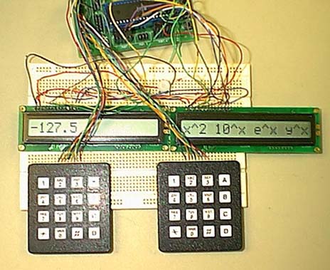
To make the project independent from the laboratory computers, we used two keypads and two LCD’s. The numeric keypad is used to input the operands for the functions. Once the operands have been entered the function keypad is used to select the functions. Since there are two LCD’s one is used to display the operands as they are entered and results when computed. The second LCD is for selecting the function that we wish to use from the eight function categories. Once the desired function has been selected the result is immediately displayed on the first LCD.
All of the mathematical computation was done using 16-bit fixed-point notation. The first eight bits representing the integer and the last eight bits were used to represent the decimal portion of the number.
Each of the functions was made using the Atmel assembler instructions. We started with the most fundamental functions (i.e. add, subtract, etc) and then moved onto the complex functions (i.e. sine, ln, etc.) This strategy proved useful because some of the complex functions used Taylor Series Expansion, which used the fundamental functions as a basis for assembling each of the terms of the series.
Program/Hardware Design
The divide algorithm (A/D):
Xn+1 = Xn(2-D*Xn) was used to calculate 1/D. In four iterations we have an answer that is very close to 1/D. The first guess is determined from a table of 16 values which can be seen in our code. Once we have the inverse we use our multiply routine to calculate A/D.
The square root algorithm:
The main program sat in a loop that scanned for keypad entries. Once enter has been depressed twice on the numeric keypad, signifying that we have entered the operands, the function keypad is activated. This function keypad is now scanned for function group selection. When a group is selected it appears on the function LCD with each of the functions that comprise that group. The groups are divided as follows:
Our enter function first determines the position of the decimal point in the buffer and stores that value in ptind. The current spot in the buffer that Z points to is held by charin. It then checks to see if the first item in the buffer is a negative sign. If so it sets a flag and strips this out of the buffer. We then use a table of powers of 10 to determine the high and low bytes of the number. We determine the high byte first. In the high byte we multiply the current number in the buffer time 10^(charin – ptind – 1). When charin equals ptind we switch over to forming the low byte. In the low byte we multiply the current number in the buffer by 10^(charin – ptind).
Hardware Design
General Layout:
 |
Pin 1 -- row 1 2 3 A Pin 2 -- row 4 5 6 B Pin 3 -- row 7 8 9 C Pin 4 -- row * 0 # D Pin 5 -- col 1 4 7 * Pin 6 -- col 2 5 8 0 Pin 7 -- col 3 6 9 # Pin 8 -- col A B C D |
(a) Each switch shorts one row to one column.
(b) Each pin should be connected to one bit of an i/o port.
(c) The i/o port pins will be used both as inputs and outputs. When they are inputs, they should have the pullup resistors activated.
In this project we use 2 keyboards, one for entering numbers and one to choose functions and menus. The numerical keypad is connected to port D and the function keypad is connected to port B. The layout is as below:
Calculation LCD |
|||
1 |
2 |
3 |
Enter |
4 |
5 |
6 |
Clear |
7 |
8 |
9 |
· |
|
|
0 |
|
- |
Numerical Keypad and LCD
Menu LCD |
|||
F1 |
F2 |
F3 |
F4 |
Math |
Trig |
Logic |
More |
Conv |
Expo |
Logs |
Test |
|
|
|
|
Other |
Function Keypad and Menu LCD
The way we read the keyboards is with a scanning routine. First we set all the lower lines to outputs and pull them low and read in the upper lines which are inputs. Then we set the upper lines to outputs and pull them low and read in the lower lines which are inputs. We combine these to be an 8 bit number which should only have two 0’s, one in the lower nibble and one in the upper nibble. We then use a table lookup to determine which button was pressed based on which bits are 0’s. The routine returns a number between 0 and 16, where 0 – 15 represent each of the buttons on the keypad and 16 represents no button pressed. Below is a diagram that shows which buttons correspond to which numbers.
|
LCD |
|||
|
0 |
4 |
8 |
12 |
|
1 |
5 |
9 |
13 |
|
2 |
6 |
10 |
14 |
|
3 |
7 |
11 |
15 |
Sample Keypad and LCD
In order to drive the two LCDs necessary to do this project we needed to change some of the code in the LCD subroutines and do new wiring. What we ended up doing is giving both LCDs a common data bus and then driving them with their own set of control lines. The description of this can be seen below
Number LCD:
|
LCD Pin |
Connection |
|
1 |
gnd - Port A0 |
|
2 |
+5 volts - PortA7 |
|
3 |
trimpot wiper |
|
4 |
PortA6 |
|
5 |
PortA5 |
|
6 |
PortA4 |
|
7-10 |
No connection |
|
11 |
PortC0 |
|
12 |
PortC1 |
|
13 |
PortC2 |
|
14 |
PortC3 |
Function LCD
|
LCD Pin |
Connection |
|
1 |
gnd - Port A0 |
|
2 |
+5 volts - PortA7 |
|
3 |
trimpot wiper |
|
4 |
PortA3 |
|
5 |
PortA2 |
|
6 |
PortA1 |
|
7-10 |
No connection |
|
11 |
PortC0 |
|
12 |
PortC1 |
|
13 |
PortC2 |
|
14 |
PortC3 |
Results of the Design
The overall results of our design were very positive. Our functions all work and most calculations are accurate to about .01. We did find a few minor bugs. One interesting bug occurs when we need to round from a decimal to an integer. For example adding .5 and .5. Instead of 1, we get ‘.:’. We believe that this problem is caused by the inaccuracies in the conversion. Another interesting thing we noticed with our Taylor Series algorithms is that the closer we get to our boundary conditions the more inaccurate our results are. None of the algorithms take extreme or even noticeable time to calculate.
What We Would Do Different Next Time
If we get the chance to work on our next design, TI R2D2, we would like to fix a few things. We would like to make our numbers 32 bits as we believe this might give us more accuracy and greater flexibility. Also, we failed to implement all of the error checking that should have been done, making this product not incredibly stable for joe-shmoe anyguy to use. Our next release would definitely include these error checks. Another improvement we could make is to find a better way of implementing one operand instructions and utilizing the results of the last operation. And of course, our bugs need fixing, and this would be something else we would fix in R2D2.
Appendix A