|
Whack-A-Cap: miniature representation of a popular amusement game ELE EE 476 Final Project by Gigi T Lam & Euborn Y Chiu |
Table of Contents (jump ahead):
Introduction:
Our final project code calls
for the implementation of an amusement game often bannered as "Test-Your-Strength"
or less accurately (but more commonly) known as "Whack-a-Mole."
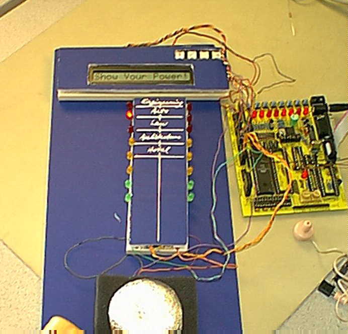
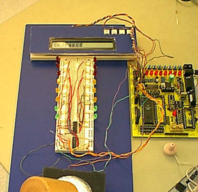
Our machine is in essence a miniturized version of what can be found in
most theme parks across the world. Its construction involves a spring load
plastic cap to act as a surface for contact, a wooden mallet which the
player uses to hit the plastic cap, and most importantly, a device, called
an accelerometer, to measure the shock forces created by the impact of
the mallet and the cap surface. A potential player would proceed to hit
the plastic cap with the mallet provided, and depending on the level of
force registered by the accelerator, a winning or losing result will be
annouced visually through a liquid crystal display and light emitting diodes,
as well as musically through the use of a speaker.
Schematic:
The schematic layout of our project is realized
as follows:
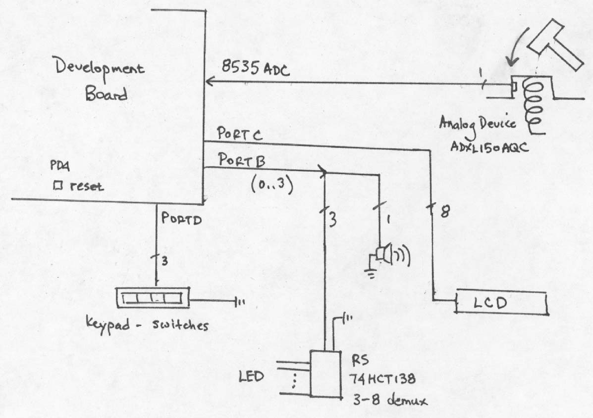
An 8535 development board was choosen for this project because we require
an analog to digital conversion process to capture voltage values (as a
function of g forces experienced) as they are registered by the accelerometer.
Having decided on a chip to use for our project, we proceeded to the programming
stage. Our approach was to design a state-machine with three states. The
following paragraphs will explain the functions and reasoning behind each
state.
Machine States:
Upon power up, our machine enters a welcome
state. In this state, the following events occur: First, a series of tones
are played through the speaker, and each note has an associated LED that
lights up accordingly. The LCD displays a welcoming message, and the keypad
is sensed for any button presses. At this point, the game operator has
the option of setting game input sensitivity for a male or female player.
A force of 49g and 40g is required to win in the male and female modes
respectively.
Our program exits the welcome state when a keypad button
is depressed, and proceed to the wait state where it loops until an acceptable
input is received from the accelerometer. In this waiting state, a loop
is used to monitor the output from the analog-to-digital conversion complete
interrupt. We reject all motions of 20g or less to minimize noise, environmental
vibrations, but most importantly mis-hits. As soon as a force greater than
20g is experienced, our program compares the value to the one set forth
by the operator (i.e., male or female) and goes into a display state. In
the display state, depending on results of the player's attempts, we either
flash the LEDs rapidly (to indicate a win) or hold the LEDs at a certain
position to represent relative effort (to indicate a loss). The display
state does not end until the operator presses a soft-reset button, and
when this happens we revert back to the welcome state.
Music:
Music is generated by creating square like waveforms
to an output pin of the 8535 microprocessor. To create a note at, for example,
500Hz, we calculate that an output inversion each millisecond is needed.
A output inversion at that rate produces a periodic signal of 2 milliseconds
each cycle, which when fed to the speaker produces an audible note at 500
Hz. Using timer zero with a prescaler value of 64, we are able to create
the range of sound desired by switching output values at each timer overflow
interrupt. To obtain different notes we simply reloaded various values
into TCNT0 at each overflow interrupt. This causes the interrupt to be
called at different time frequencies. We then came up with a scheme to
store the frequency and duration desired into memory. Each note is represented
as a frequency-duration pair. For example, a value of (192,248) corresponds
to a 500 Hz played for a quarter of a second. Using this convention, we
programmed each note in our melody as frequency-duration pairs in memory.
Whenever music is desired, timer zero is initialized, our machine then
reads each value from memory sequentially, plays it for the duration required,
and loads the next one. This process is repeated until a ending zero is
reached. To acheive periods of silence (mute) in speaker output, it is
decided that a value of (1,don't care) be used.
| Frequency [Hz] | Reload Value |
Duration Value for .25 Seconds |
| 194 | 96 | 98 |
| 218 | 113 | 136 |
| 260 | 136 | 131 |
| 386 | 175 | 195 |
| 434 | 184 | 220 |
| 500 | 192 | 248 |
| 512 | 195 | 255 |
| 292 | 149 | 100 |
| 326 | 160 | 110 |
| 343 | 165 | 130 |
| SILENCE | 1 | DONT CARE |
Light Emitting Diodes:
Sychronized with the beats of music are sixteen
light emitting diodes driven by two Radio Shack 74HCT138 demultiplexors.
Seeing that the number of output pins on our microprocess are quickly being
taken up by switches, LCD, accelerometer, and speaker, we see no way of
driving sixteen LEDs without the use of a bus output to some sort of decoder.
The Radio Shack decoder was choosen for its simplicity and ability to drive
20mA of current at each output pin. A pair of 74HCT138 takes output from
pins b1 to b3 and lights up LEDs as required. Output to LEDs are always
latched until the next timer zero overflow interrupt. This allows for easy
sychronization with music when needed. If a LED is to maintain its value,
then the same value can always be relatched into output register (LED).
Accelerometer:
The Analog Devices ADXL150AQC accelerometer
is capable of recording shocks of up to 50g in both directions of one axis.
The output of the accelerometer is dicated by the equation 2.5-(.038g)
[Volts] where g is the force in g's experienced. We phyiscally mounted
the accelerometer in such a way that the larger the g force, the small
Vout becomes. In other words, a 49g impact will register as approximately
0.64 [Volts] whereas a 20g impact will cause 1.74 [Volts] at the output.
When input from the ADXL150AQC is needed, the ADC is
allowed to cycle in free-run mode without noise cancelling, and the ADC
complete interrupt is used to capture values from the ten-bit capture register.
We used an Aref setting of 4.096 [Volts] so that, similiar to lab five,
the least significant bit in the capture register accounts for about 4
[mV]. This becomes helpful when we scale the output value into a score.
Since are mostly interesting in the range of activity between zero to 50g,
we can simply translate the voltage received into a score between zero
to one hundred by manipulating the ADC results by a factor of two.
Our accelerometer is mounted to the inside of a plastic
cap with silicon rubber so that is aligned with the verticle axis. The
plastic cap is then spring loaded with energy absorbing foam layers to
help disperse excess energy as the cap is depressed with a mallet. The
fact that our ADXL150AQC came in a surface mount package made it difficult
to soldier but greatly simplified the mounting process by virtue of its
small size.
Conclusion:
"Whack-A-Cap" is in effect a
culumation of what we have learned this semester. It contains many bits
and pieces from various labs, but we have improved on many things to make
it a complete product as opposed to a congregation of modular code (that
approach would have not worked anyhow). For example, we used the instruction
lpm (something learned while studying LCD) to retrieve music material from
memory, restructed the LCD code to use more relative branches and calls
to save program memory, and used external circuitry like the decoder to
ease internal programming requirments. We believe these improvements have
made the final program possible in a very efficient, manageable way. The
ADXL150AQC also works remarkably well, although with a better budget we
would have opted for a version of larger range (perhaps on the scale of
250g) so that we may take harder hits before setting off a game-winner.
|
LCD |
Connect |
Switch |
Connect |
Spkr |
Connect |
LED |
Connect |
Accelerometer |
Connect |
|
1 |
Gnd |
1 |
PD0 |
IN |
PB0 |
A0-2 |
PB1-3 |
Vout |
PA0 (Aref) |
|
2 |
Vcc |
2 |
PD1 |
Gnd |
Gnd |
||||
|
3 |
Trimpot |
||||||||
|
4 |
PC6 |
||||||||
|
5 |
PC5 |
||||||||
|
6 |
PC4 |
||||||||
|
7 - 10 |
N/C |
||||||||
|
11 |
PC0 |
||||||||
|
12 |
PC1 |
||||||||
|
13 |
PC2 |
||||||||
|
14 |
PC3 |
||||||||
The End: 5/5/1999 Euborn Chiu Gigi Lam