High Level Design
The control logic for our design is implemented within a state machine.
The state diagram is available in the appendix. We based our states and state transitions
on the specifications of actual alarm systems. We implemented features from various products
based on usefulness and feasibility.
The state machine consists of six states:
Arm -- Lock doors, blink status LED,
monitor all inputs.
Disarm -- Unlock doors, turn off status LED.
Valet -- Turn on status LED, disable auto-arming.
Panic -- Turn on siren, toggle locks.
Active -- Turn on siren for siren duration.
Program -- Turn off LEDs, open RS232 communication.
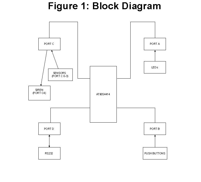
We assign the ports in the following manner:
Port A -- control LEDs.
Port B -- push buttons.
Port C -- sensor/trigger and siren output.
Port D -- RS232 interface.
Block diagram